EP4553373A1 - Élément creux de fixation, ensemble et ensemble - Google Patents
Élément creux de fixation, ensemble et ensemble Download PDFInfo
- Publication number
- EP4553373A1 EP4553373A1 EP24211145.8A EP24211145A EP4553373A1 EP 4553373 A1 EP4553373 A1 EP 4553373A1 EP 24211145 A EP24211145 A EP 24211145A EP 4553373 A1 EP4553373 A1 EP 4553373A1
- Authority
- EP
- European Patent Office
- Prior art keywords
- hollow
- fastening
- fastening element
- sound
- component
- Prior art date
- Legal status (The legal status is an assumption and is not a legal conclusion. Google has not performed a legal analysis and makes no representation as to the accuracy of the status listed.)
- Pending
Links
Images







Classifications
-
- F—MECHANICAL ENGINEERING; LIGHTING; HEATING; WEAPONS; BLASTING
- F21—LIGHTING
- F21S—NON-PORTABLE LIGHTING DEVICES; SYSTEMS THEREOF; VEHICLE LIGHTING DEVICES SPECIALLY ADAPTED FOR VEHICLE EXTERIORS
- F21S8/00—Lighting devices intended for fixed installation
- F21S8/02—Lighting devices intended for fixed installation of recess-mounted type, e.g. downlighters
- F21S8/026—Lighting devices intended for fixed installation of recess-mounted type, e.g. downlighters intended to be recessed in a ceiling or like overhead structure, e.g. suspended ceiling
-
- H—ELECTRICITY
- H02—GENERATION; CONVERSION OR DISTRIBUTION OF ELECTRIC POWER
- H02G—INSTALLATION OF ELECTRIC CABLES OR LINES, OR OF COMBINED OPTICAL AND ELECTRIC CABLES OR LINES
- H02G3/00—Installations of electric cables or lines or protective tubing therefor in or on buildings, equivalent structures or vehicles
- H02G3/02—Details
- H02G3/08—Distribution boxes; Connection or junction boxes
- H02G3/12—Distribution boxes; Connection or junction boxes for flush mounting
- H02G3/123—Distribution boxes; Connection or junction boxes for flush mounting in thin walls
-
- F—MECHANICAL ENGINEERING; LIGHTING; HEATING; WEAPONS; BLASTING
- F21—LIGHTING
- F21V—FUNCTIONAL FEATURES OR DETAILS OF LIGHTING DEVICES OR SYSTEMS THEREOF; STRUCTURAL COMBINATIONS OF LIGHTING DEVICES WITH OTHER ARTICLES, NOT OTHERWISE PROVIDED FOR
- F21V21/00—Supporting, suspending, or attaching arrangements for lighting devices; Hand grips
- F21V21/02—Wall, ceiling, or floor bases; Fixing pendants or arms to the bases
- F21V21/04—Recessed bases
- F21V21/047—Mounting arrangements with fastening means engaging the inner surface of a hole in a ceiling or wall, e.g. for solid walls or for blind holes
-
- B—PERFORMING OPERATIONS; TRANSPORTING
- B23—MACHINE TOOLS; METAL-WORKING NOT OTHERWISE PROVIDED FOR
- B23B—TURNING; BORING
- B23B51/00—Tools for drilling machines
- B23B51/04—Drills for trepanning
-
- H—ELECTRICITY
- H02—GENERATION; CONVERSION OR DISTRIBUTION OF ELECTRIC POWER
- H02G—INSTALLATION OF ELECTRIC CABLES OR LINES, OR OF COMBINED OPTICAL AND ELECTRIC CABLES OR LINES
- H02G3/00—Installations of electric cables or lines or protective tubing therefor in or on buildings, equivalent structures or vehicles
- H02G3/02—Details
- H02G3/08—Distribution boxes; Connection or junction boxes
- H02G3/18—Distribution boxes; Connection or junction boxes providing line outlets
- H02G3/20—Ceiling roses or other lighting sets
Definitions
- the invention relates to a fastening hollow element for fastening an electrically operated functional assembly, a set comprising at least one such fastening hollow element and a tool therefor, as well as an arrangement with a component, such a fastening hollow element and an electrically operated functional assembly.
- the DE 10 2011 051 513 A1 a self-tapping mounting ring for installing a recessed light and a tool for its assembly.
- the object of the invention is to provide a simple, reliable and preferably aesthetically pleasing fastening solution for a functional assembly in the region of a component formed with a sound-absorbing material, in particular a plate- or panel-shaped component of this type.
- a hollow fastening element for fastening an electrically operated functional assembly in a component formed from a sound-absorbing material, in particular a plate- or panel-like component.
- the hollow fastening element has a receiving space for at least partially receiving the functional assembly and a screw-like threaded device running around the outside of the hollow fastening element.
- the threaded device is arranged and designed to work its way into the sound-absorbing material when a screwing movement is applied to the hollow fastening element and, through interaction of the threaded device with the sound-absorbing material, to hold the hollow fastening element and the received functional assembly to the component formed from the sound-absorbing material.
- a set comprising at least one such fastening hollow element according to the invention and a screwing-in tool for inserting the fastening hollow element or the fastening hollow element with a functional assembly permanently installed therewith into a component formed with a sound-absorbing material, in particular a plate-like or panel-like component, is proposed.
- the invention provides an arrangement comprising a component formed with a sound-absorbing material, in particular a plate-like or panel-like component, in particular an acoustic ceiling component, a hollow fastening element according to the invention inserted into the component, and an electrically operated functional assembly accommodated in the hollow fastening element.
- a component formed with a sound-absorbing material in particular a plate-like or panel-like component, in particular an acoustic ceiling component
- a hollow fastening element according to the invention inserted into the component, and an electrically operated functional assembly accommodated in the hollow fastening element.
- a hollow fastening element according to the invention can be installed into a particularly relatively soft, sound-absorbing component, such as an acoustic ceiling, by means of a simple twisting and screwing movement.
- a particularly relatively soft, sound-absorbing component such as an acoustic ceiling
- the threaded device which is adapted to be machined into the sound-absorbing material and, thanks to its circumferential design, advantageously provides a contact surface that enables a firm, reliable holding and fixing of the hollow fastening element in the sound-absorbing material after the screwing-in process.
- the machining or "cutting-in" of the circumferential threaded device can be carried out in a defined and clean manner.
- the assembly of the functional assembly in the component formed with the sound-absorbing material is thus considerably simplified, and complicated fastening with a multitude of parts, such as screws and the like that must be individually and separately fixed, is avoided.
- Fastening according to the invention is thus also time-saving and cost-effective.
- the component formed with the sound-absorbing material, in which the functional assembly can be attached by means of the hollow fastening element is an acoustic ceiling component.
- the hollow fastening element thus enables the advantageously reliable, simple, and quick attachment of the functional assembly to an acoustic ceiling whose material is relatively soft for sound insulation and acoustic improvement.
- the receiving space is designed as an axially continuous cavity. This allows heat, for example, to escape easily from the rear.
- the threaded device is arranged surrounding the receiving space. This advantageously allows the received functional assembly to be held and fixed particularly well.
- the hollow fastening element has a circumferential retaining groove in the receiving space.
- the functional assembly for example as a separately provided functional unit, can be easily and reliably held in such a retaining groove by means of a snap-in or locking connection through the engagement of a snap-in or locking element in the retaining groove. Furthermore, easy detachment from the hollow fastening element is enabled when needed.
- the hollow fastening element has two or more angled coupling recesses distributed along a circumferential direction of the receiving space.
- Such coupling recesses can be used, for example, to establish a mechanical bayonet connection between the hollow fastening element and a functional assembly, particularly one embodied as a separately provided functional unit.
- the fastening hollow element has an engagement geometry for a screwing tool for applying the screwing movement.
- a screwing tool for applying the screwing movement.
- only a small part of the fastening hollow element can protrude from the component formed with the sound-absorbing material.
- the hollow fastening element has a circumferential, interrupted rib in the receiving space, which is provided with recesses distributed in a circumferential direction of the receiving space.
- the recesses interrupt the rib and are preferably arranged uniformly distributed along the circumferential direction of the receiving space. Such recesses can expediently provide the engagement geometry.
- the threaded device is formed with a rib that is wound in a thread-like manner on the outside of the hollow fastening element and extends continuously around it.
- the rib can, for example, be designed such that it extends more than one revolution, in particular more than two revolutions, around the hollow fastening element.
- the rib is, in particular, continuous. Such a rib enables an advantageous contact surface with the sound-absorbing material in order to securely and firmly fix the hollow fastening element.
- the circumferential rib can taper in cross-section toward a free edge of the rib. This advantageously contributes to facilitating the incorporation or cutting of the rib into the sound-absorbing material. Consequently, less force is required to screw in the hollow fastening element, thus also applying less force to the component formed with the sound-absorbing material, and damage, fraying, etc., is avoided.
- the hollow fastening element is designed with a substantially circular-cylindrical outer basic shape. Such a design can be advantageous with regard to the execution of the screwing movement and sufficient space for accommodating the functional assembly in the hollow fastening element.
- the hollow fastening element is formed in one piece. Such a hollow fastening element is simple and convenient to handle.
- the hollow fastening element can be manufactured using a generative manufacturing process, in particular by means of 3D printing. In this way, the hollow fastening element can also be equipped with more complex geometric features and/or can be economically manufactured in smaller series.
- the hollow fastening element can be cast, for example, by injection molding or die casting, which can be economical, especially for larger quantities.
- the hollow fastening element can be made of a plastic material or a metal material, particularly aluminum or an aluminum alloy.
- a plastic material is relatively lightweight and can be cost-effective, while a metal material can enable an even more robust hollow fastening element.
- the hollow fastening element is designed to releasably receive a functional unit as the functional assembly.
- a functional unit is thus a mounting device (also referred to as a "mounting set"), which is first assembled and into which the separately provided functional unit is then inserted.
- the functional unit such as a lighting unit, a sensor unit, or a loudspeaker unit, can be easily removed or replaced as needed, for example, in case of damage, for cleaning purposes, or if it becomes dirty, etc.
- the hollow fastening element is designed as a housing element and is intended to permanently accommodate the functional assembly in the receiving space.
- the functional assembly and the hollow fastening element thus form a cohesive, pre-assembled unit that can be installed as a whole in the component formed with the sound-absorbing material.
- the hollow fastening element further comprises a material separation device and can be inserted into the solid sound-absorbing material by applying the screwing movement, forming a removable core of the sound-absorbing material through the action of the material separation device.
- This configuration enables fastening in the component formed with the sound-absorbing material without the prior creation of an opening, such as a round hole, in the component, for example by cutting it out. Instead, in this configuration, fastening takes place in one step into the solid material.
- the material separating device can be omitted.
- a recess, such as a hole, for receiving the hollow fastening element is created in advance in the component in a separate step, for example, by cutting or sawing.
- the material separation device is arranged surrounding the receiving space. This allows the core to be separated in such a way that an opening or hole of suitable size is created for receiving the hollow fastening element.
- the material separation device is arranged on a front edge of a circumferential wall of the hollow fastening element. This allows the material separation device to exert its effect particularly effectively and already upon application of the hollow fastening element to a surface of the component.
- the material separation device has a circumferential arrangement of teeth, in particular saw teeth. Such teeth enable effective material separation and effective core formation.
- the teeth radially outside continue a substantially cylindrical outer circumferential surface area of the fastening hollow element in sections and radially inside form sections of a funnel-like tapered surface, such that the teeth at each tooth base essentially reach the outer wall thickness of the hollow fastening element.
- Teeth designed in this way enable precise separation of the core from the material and a cleanly machined opening. The threaded device can then easily be machined into the clean inner parting surface of the opening.
- the material separation device and the threaded device are provided on the hollow fastening element at a distance from one another along a rotational axis, by rotating which the hollow fastening element can be screwed into the solid sound-absorbing material. This allows for good guidance of the hollow fastening element before the threaded device takes effect.
- the hollow fastening element is formed with a conical end portion that can be recessed into a visible surface of the component formed with the sound-absorbing material. In this way, the fastening element can be inserted, for example, flush with or with a slight offset from a visible surface of the component formed with the sound-absorbing material.
- the hollow fastening element is designed to be smooth on one of its visible ends. This allows for fastening with a visually clean, attractive edge that is flush with the component formed with the sound-absorbing material, for example, surrounding the functional assembly.
- the hollow fastening element has a rib-and-groove structure on a visible end face thereof.
- a rib-and-groove structure can facilitate at least partial filling of the end face of the hollow fastening element and subsequent painting.
- the adhesion of the filler to the end face can be improved by the ribs and grooves.
- the insertion tool is designed with arms arranged such that, when the insertion tool is used to insert the hollow fastening element or the hollow fastening element with the permanently installed functional assembly, the arms rest on the visible side of the hollow fastening element by means of a screwing movement and protrude beyond a visible outer edge of the hollow fastening element. This prevents the hollow fastening element from being screwed in too far.
- the functional assembly is designed as a lighting assembly.
- the functional assembly may be designed as a sensor assembly or as a loudspeaker assembly.
- the functional assembly is designed as a functional unit detachably received in the hollow fastening element, for example as a lighting unit or sensor unit or loudspeaker unit.
- the functional unit is held in the fastening hollow element by means of ball snap devices arranged on the outside of the functional unit.
- the functional unit is coupled to the hollow fastening element in a bayonet-like manner.
- the functional assembly is permanently installed with the hollow mounting element as a housing element.
- the hollow mounting element can form a single unit with the functional assembly, such as a light, a sensor module, or a loudspeaker module.
- the sound-absorbing material is made of a fibrous or porous material. Such materials can exhibit good sound insulation properties.
- the sound-absorbing material can be formed with a glass wool material, a glass fiber material, a mineral wool material, a felt-like material, a foam material or a fabric.
- the sound-absorbing material may have a lower hardness than a material of the threaded device of the fastening hollow element.
- Fig. 1-9 illustrate a fastening hollow element 1, designed as a so-called “mounting set” for fastening an electrically operated, in Fig. 1-2 not shown, designed as a functional unit, for example a lighting unit, as well as the introduction and mode of operation of the hollow fastening element 1.
- the functional assembly 100 can be designed as a sensor unit or a loudspeaker unit instead of as a lighting unit.
- the fastening hollow element 1 is designed to be inserted into a plate- or panel-like component 50 of an acoustic ceiling formed with a sound-absorbing material 51 in order to fasten the functional assembly 100 in the component 50.
- the hollow fastening element 1 is formed in one piece and has a substantially circular-cylindrical outer basic shape.
- the hollow fastening element 1 can be produced generatively using 3D printing or, in some variants, can be injection-molded or die-cast instead, for example, for larger quantities.
- the hollow fastening element 1 is made, for example, from a plastic material or a metal material, in particular aluminum or an aluminum alloy.
- the hollow fastening element 1 is formed with a substantially hollow-cylindrical, circumferential wall 6.
- a threaded device 3 runs screw-like around the hollow fastening element 1.
- the threaded device 3 is formed with a rib 8, which, starting from a radially outer side of the wall 6, initially rises and winds itself thread-like around the hollow fastening element 1 for more than two turns.
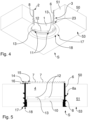
- the rib 8 extends uninterruptedly and continuously around the outside of the hollow fastening element 1. In a cross-section of the rib 8, see e.g. Fig. 5 and 9 , the rib 8 runs radially into a pointed, angular free edge 8a.
- the hollow fastening element 1 further comprises a material separating device 2, which is arranged on a front edge 5 of the wall 6 and is formed with a circumferential arrangement of teeth 7 shaped as saw teeth.
- the teeth 7 continue a substantially cylindrical outer circumferential surface area 14 of the hollow fastening element 1 in sections.
- surface sections of the teeth 7 form areas of a funnel-shaped tapered surface 15.
- the teeth 7 essentially reach an outer wall thickness 16 of the fastening hollow element 1 at their tooth base, see Fig. 5 .
- a continuous cavity extends axially through the fastening hollow element 1, which forms a receiving space 4 for the functional assembly 100.
- the functional assembly 100 can be at least partially, in the first embodiment in particular essentially completely, see Fig. 9 , which will be recorded and accommodated in recording room 4.
- the threaded device 3 and the material separating device 2 surround the receiving space 4 along a circumferential direction of the fastening hollow element 1.
- a retaining groove 10 is provided around it, into which ball snap devices 110 with spring-loaded balls arranged on the outside of the functional unit 100 can engage in order to releasably hold the functional unit 100 in the receiving space 4, see e.g. Fig. 8A and 9 .
- An acoustic ceiling is a ceiling system designed to improve the acoustic quality of a room. To achieve this, the acoustic ceiling can reduce noise levels by absorbing sound waves.
- the plate- or panel-like acoustic ceiling component 50 is made of a relatively soft, sound-absorbing material 51, thus improving the acoustic properties of the room.
- the material 51 has properties that promote sound insulation and acoustic improvement.
- the material 51 is a fibrous or porous material or contains such a material.
- the material 51 can be made of glass fibers or glass wool, mineral wool, felt, foam, or fabric, or a combination of such materials.
- the material 51 is significantly softer than the material of the hollow fastening element 1 and in particular of the threaded device 3.
- the material 51 can be softer than, for example, a plasterboard panel of a conventional suspended ceiling.
- the material 51 is sufficiently dimensionally stable to produce plates or panels from it.
- plasterboards do not have any significant inherent sound insulation properties, in some cases they may reflect or even amplify sound and thus do not make a significant contribution to acoustic improvement, unlike component 50 of the acoustic ceiling.
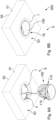
- Fig. 3A, 3B, 3C, 3D show successive states during such a screwing or driving process.
- the fastening hollow element 1 is attached to a visible surface 53 of the component 50 at any desired location, see Fig. 3A , and cuts into the surface 53 by means of the material cutting device 2, see Fig. 3B After sufficient cutting into the material 51, the thread device 3 comes into engagement with the material 51 and thereby works its way into it, see Fig. 3C until the fastening hollow element 1 is flush with the surface 53 on a visible end face 18.
- a visible side is designated by the reference symbol S.
- a conical end section 23 on which a frontal outer edge 17 is formed, is sunk into the material 51, see e.g. Fig. 4 .
- the end section 23 has a flat surface in the area of the visible end face 18, which then merges flush with the surface 53 and forms a clean edge finish.
- the hollow fastening element 1 is securely fixed to the acoustic ceiling component 50. After inserting the functional assembly 100 into the receiving space 4, it is also reliably held to the component 50.
- the hollow fastening element 1 can be removed without damage, or at least with minimal damage, by unscrewing it if necessary.
- the hollow fastening element 1 is screwed into the solid sound-absorbing material 51, forming a core 52 that can be removed from a top side of the component 50. Thus, no hole needs to be pre-cut for the hollow fastening element 1 before inserting it.
- FIG. 8B A completed arrangement 200 according to the first embodiment with the acoustic ceiling component 50, the hollow fastening element 1 inserted therein and the functional assembly 100 detachably held in the hollow fastening element 1 and designed as a lighting unit is shown in Fig. 8B .
- the hollow fastening element 1 has, in the receiving space 4, an interrupted rib 12 extending circumferentially on an inner side of the wall 6, which is provided with recesses 13 evenly distributed in the circumferential direction of the receiving space 4.
- the recesses 13 each interrupt the rib 12 and serve as an engagement geometry 11 for a screwing tool 60 for applying the screwing movement 70.
- the insertion tool 60 has four arms 61, which are evenly distributed at 90-degree intervals around a central axis M of the tool 60.
- the central axis M of the insertion tool 60 corresponds to the rotation axis 9.
- one of four engagement ribs 62 is arranged, which extend substantially longitudinally along the tool 60, substantially parallel to the central axis M.
- the extension of the arms 61 radially to the axis M is greater than that of the ribs 62.
- the engagement ribs 62 can each be inserted into one of the recesses 13 such that they abut one edge of the recess 13. To insert the hollow fastening element 1, it can be screwed in using the tool 60, as illustrated by reference numeral 70, until the hollow fastening element 1 is flush with the surface 53.
- the arms 61 provide good handling for the installer.
- the arms 61 are designed and arranged such that, when the screwing-in tool 60 is used to insert the hollow fastening element 1 by means of the screwing movement 70, they rest on the visible side of the hollow fastening element 1, i.e., on its visible end face 18, and at the same time protrude beyond the visible outer edge 17 of the hollow fastening element 1.
- the hollow fastening element 1 can only be screwed in until it is flush with the surface 53 of the component 50. This enables reproducible, clean assembly.
- the upper side regions of the arms 61 facing the hollow fastening element 1 preferably form part of a common plane normal to the central axis M.
- rib 8 at both end regions of the threaded device 3 rises or falls again from the cylindrical outer side of the wall 6, in the sense of the radial dimension of the rib 8.
- Fig. 9 shows the rise in the end region of the threaded device 3 facing the material cutting device 2, as well as the decrease in the radial height of the rib 8 in the end region facing the conical end section 23. This initially enables clean machining into the material 51 and, finally, clean countersinking of the end section 23 into the surface 53.
- a fastening kit is also provided for the functional assembly 100 designed as a lighting unit, which includes the hollow fastening element 1 and the tool 60.
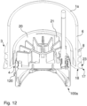
- a fastening hollow element 1a according to a second embodiment is shown in the Fig. 10-12 , whereby its differences compared to the first embodiment are described below.
- the threaded device 3 is configured in the hollow fastening element 1a as in the first embodiment, but the material separating device 2 is omitted in the second embodiment. Therefore, in order to insert the hollow fastening element 1a into the acoustic ceiling component 50, a round hole is first cut into the component 50, for example, using a hole saw, a jigsaw, or similar. The hollow fastening element 1a is then the procedure in the first embodiment, screwed into the already existing, pre-cut, hole in the component 50.
- the hollow fastening element 1a differs from the hollow fastening element 1 in that, instead of the circumferential retaining groove 10 in the hollow fastening element 1a, several, for example three, angled coupling recesses 21 are provided in the receiving space 4, evenly distributed in the circumferential direction of the hollow fastening element 1a. These are, for example, introduced as flat grooves into an inner side of an inner circumferential wall 20, which extends parallel and coaxially to the wall 6, but is considerably shorter than the latter.
- a functional assembly 100a can be accommodated in the receiving space 4 of the hollow fastening element 1a, which in turn is designed, for example, as a lighting unit or can instead be designed as a sensor unit or a loudspeaker unit.
- the functional assembly 100a has radially outward-facing projections 120, each of which can engage in one of the recesses 21. In this way, the functional unit 100a can be connected to the hollow fastening element 1a in a bayonet-like manner.
- Fig. 10 shows an arrangement 200a with the acoustic ceiling component 50, the hollow fastening element 1a screwed into it and the functional assembly 100a designed as a lighting unit.
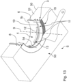
- a fastening hollow element 1b according to a third embodiment illustrates the Fig. 13 and 14 .
- the fastening hollow element 1b is designed like the fastening hollow element 1, with the exception of its design in the area of its visible end face 18 and the absence of the material separating device 2, can be screwed into the acoustic ceiling component 50 by means of the tool 60 and can accommodate the functional assembly 100.
- the visible end face 18, see Fig. 14 not smooth as in the first and second embodiments, but instead formed with a front-side rib-and-groove structure 19.
- the rib-and-groove structure 19 has alternating ribs and grooves that extend substantially radially to the axis of rotation 9, thus the longitudinal center axis of the hollow fastening element 1b.
- Radially inward, toward the receiving space 4, the rib-and-groove structure 19 is terminated by a circumferential limiting projection 19', which projects beyond the ribs of the rib-and-groove structure 19 in the axial direction of the hollow fastening element 1b.
- each of the arms 61 can abut the limiting projection 19'.
- the recessed rib-groove structure 19 creates a flat area that can be filled with filler 54 suitable for acoustic ceilings, see Fig. 13
- the hollow fastening element 1b can be installed particularly discreetly and inconspicuously, virtually without a border.
- the ribs and grooves allow the filler 54 to adhere well.
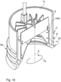
- a fastening hollow element 1c, and an exemplary luminaire as a functional unit formed with the fastening hollow element 1c, show Fig. 15 and 16 in accordance with a fourth embodiment.
- the hollow fastening element 1c differs from the hollow fastening element 1 primarily in that the material separating device 2 is omitted, so that in the fourth embodiment, a hole is also pre-cut in the acoustic ceiling component 50.
- the fastening hollow element 1c has an inner circumferential wall 22 which is shorter than the wall 6 and extends substantially coaxially and parallel thereto.
- a receiving space 4 is formed as a hollow space extending axially through the hollow fastening element 1c.
- a functional assembly 100c which is Fig. 15 and 16 is a lighting assembly, arranged in the receiving space 4 and firmly installed with the fastening hollow element 2 to form a unit.
- the functional assembly 100c could alternatively be, for example, a sensor assembly or a loudspeaker assembly.
- the hollow fastening element 1c is thus designed as a housing element of a luminaire, or alternatively, for example, another electrically operated module such as a sensor or loudspeaker module.
- the luminaire or module is screwed as a whole into an acoustic ceiling component 50 with the aid of the hollow fastening element 1c.
- Fig. 15 shows schematically an arrangement 200c with the hollow fastening element 1c screwed into the acoustic ceiling component 50 and the functional assembly 100c in the manner of a luminaire mounted directly, without the need for a separate "mounting set".
- the hollow fastening element 1a and 1c can each have an engagement geometry for a screwing tool (not shown in the figures) to facilitate screwing in the hollow fastening element 1a, 1c.
- a screwing tool not shown in the figures
- the recesses 21 in the second embodiment could serve this purpose.
- the material separating device 2 with the teeth 7 can also be omitted, or that in variants of the second, third and fourth embodiments, a material separating device 2 can be provided as in the first embodiment explained above.
- a bayonet connection analogous to that described above, can be provided instead of a locking receptacle of the functional assembly.
- the acoustic ceiling component 50 is part of a suspended acoustic ceiling. Wiring for supplying the functional modules 100, 100a, 100c is routed from the rear of the acoustic ceiling.
- an outer diameter of the hollow fastening element 1, 1a, 1b, 1c at the outer edge 17 can, for example, be between approximately 80 mm and approximately 150 mm, for example between 110 mm and 115 mm. However, other diameters are also conceivable.
- An axial length of the hollow fastening element 1, 1a, 1b, 1c can, for example, be between 35 mm and 55 mm in some variants, for example approximately 45 mm. However, other, for example longer lengths of up to 100 mm or more are also conceivable and useful. Many different diameter-to-length ratios are conceivable and can be useful.
Landscapes
- Engineering & Computer Science (AREA)
- Architecture (AREA)
- Civil Engineering (AREA)
- Structural Engineering (AREA)
- General Engineering & Computer Science (AREA)
- Connection Of Plates (AREA)
Applications Claiming Priority (1)
| Application Number | Priority Date | Filing Date | Title |
|---|---|---|---|
| ATA50908/2023A AT527717B1 (de) | 2023-11-10 | 2023-11-10 | Befestigungshohlelement, satz und anordnung |
Publications (1)
| Publication Number | Publication Date |
|---|---|
| EP4553373A1 true EP4553373A1 (fr) | 2025-05-14 |
Family
ID=93432085
Family Applications (1)
| Application Number | Title | Priority Date | Filing Date |
|---|---|---|---|
| EP24211145.8A Pending EP4553373A1 (fr) | 2023-11-10 | 2024-11-06 | Élément creux de fixation, ensemble et ensemble |
Country Status (2)
| Country | Link |
|---|---|
| EP (1) | EP4553373A1 (fr) |
| AT (1) | AT527717B1 (fr) |
Citations (6)
| Publication number | Priority date | Publication date | Assignee | Title |
|---|---|---|---|---|
| DE102011051513A1 (de) | 2011-07-01 | 2013-01-03 | Richter Lighting Technologies Gmbh | Selbstschneidender Einbauring zum Einbau einer Leuchte und Werkzeug zur Montage des Einbaurings |
| US20160172833A1 (en) * | 2013-08-05 | 2016-06-16 | Nir Velozny | Housing for electrical appliances |
| US20170054281A1 (en) * | 2014-05-02 | 2017-02-23 | Sebastián LÓPEZ RUBIO | Tubular part, embeddable electrical box, and kits formed by both |
| EP3428509A1 (fr) * | 2017-07-07 | 2019-01-16 | Bartenbach Holding GmbH | Dispositif de montage |
| CH711488B1 (de) * | 2015-09-03 | 2020-04-30 | Firalux Holding Ag | Einbaubüchsendeckel zum Verschliessen einer Öffnung in einer Einbaubüchse. |
| US11306902B1 (en) * | 2021-03-25 | 2022-04-19 | Lavon Bennett | Can light installation system |
-
2023
- 2023-11-10 AT ATA50908/2023A patent/AT527717B1/de active
-
2024
- 2024-11-06 EP EP24211145.8A patent/EP4553373A1/fr active Pending
Patent Citations (6)
| Publication number | Priority date | Publication date | Assignee | Title |
|---|---|---|---|---|
| DE102011051513A1 (de) | 2011-07-01 | 2013-01-03 | Richter Lighting Technologies Gmbh | Selbstschneidender Einbauring zum Einbau einer Leuchte und Werkzeug zur Montage des Einbaurings |
| US20160172833A1 (en) * | 2013-08-05 | 2016-06-16 | Nir Velozny | Housing for electrical appliances |
| US20170054281A1 (en) * | 2014-05-02 | 2017-02-23 | Sebastián LÓPEZ RUBIO | Tubular part, embeddable electrical box, and kits formed by both |
| CH711488B1 (de) * | 2015-09-03 | 2020-04-30 | Firalux Holding Ag | Einbaubüchsendeckel zum Verschliessen einer Öffnung in einer Einbaubüchse. |
| EP3428509A1 (fr) * | 2017-07-07 | 2019-01-16 | Bartenbach Holding GmbH | Dispositif de montage |
| US11306902B1 (en) * | 2021-03-25 | 2022-04-19 | Lavon Bennett | Can light installation system |
Also Published As
| Publication number | Publication date |
|---|---|
| AT527717A1 (de) | 2025-05-15 |
| AT527717B1 (de) | 2025-07-15 |
Similar Documents
| Publication | Publication Date | Title |
|---|---|---|
| DE69614593T2 (de) | Verankerungseinheit mit einem durch das auf den Bolzen einwirkende Drehmoment ausweitbaren Verankerungsteil | |
| DE102011051513B4 (de) | Selbstschneidender Einbauring zum Einbau einer Leuchte | |
| EP3428509A1 (fr) | Dispositif de montage | |
| EP0292742B1 (fr) | Vis d'écartement | |
| DE4041765A1 (de) | Einschraubduebel | |
| WO2014060608A2 (fr) | Dispositif d'assemblage démontable pour le montage sans outil | |
| AT507567B1 (de) | Montagevorrichtung für einbauleuchten | |
| DE102024112583A1 (de) | Trockenbaudübel und Verfahren zur Montage des Trockenbaudübels | |
| AT527717B1 (de) | Befestigungshohlelement, satz und anordnung | |
| DE19745296A1 (de) | Befestigungselement zum Befestigen von Dämmplatten an einer Unterkonstruktion | |
| DE3817100A1 (de) | Unterputzdose fuer insbesondere mauerwerks- und hohlwandmontage | |
| WO2025051555A1 (fr) | Cheville pour cloison sèche et procédé d'ajustement de la cheville pour cloison sèche | |
| CH711488B1 (de) | Einbaubüchsendeckel zum Verschliessen einer Öffnung in einer Einbaubüchse. | |
| EP2425066B1 (fr) | Cloisonnement pour aménagement intérieur | |
| DE202006014335U1 (de) | Vorrichtung zum Fixieren eines Baukörpers in einer Gebäudeöffnung | |
| AT515601B1 (de) | System zur Aufnahme von Lichtmodulen sowie Verfahren für dessen Herstellung | |
| DE4108332C1 (fr) | ||
| DE19842512C1 (de) | Anordnung zur Installation einer Einbaukomponente in eine Wandung oder einen Hohlkörper | |
| DE102006019576A1 (de) | Lenkvorrichtung für Fahrzeuge und Verfahren zur Montage einer Lageranordnung | |
| DE10052662A1 (de) | Dübel mit eindrehbarer Spreizschraube | |
| DE19710421C5 (de) | Befestigungsvorrichtung für eine Abdeckplatte eines Schornsteinkopfes | |
| DE102020205380B4 (de) | Möbel-Rückwandverbinder | |
| EP4328393A1 (fr) | Dispositif de fixation d'un objet | |
| DE69711318T2 (de) | Vorrichtung zur schnellen Befestigung und Demontierung von Platten | |
| DE202022102577U1 (de) | Vorrichtung zum Befestigen eines Gegenstands |
Legal Events
| Date | Code | Title | Description |
|---|---|---|---|
| PUAI | Public reference made under article 153(3) epc to a published international application that has entered the european phase |
Free format text: ORIGINAL CODE: 0009012 |
|
| STAA | Information on the status of an ep patent application or granted ep patent |
Free format text: STATUS: THE APPLICATION HAS BEEN PUBLISHED |
|
| AK | Designated contracting states |
Kind code of ref document: A1 Designated state(s): AL AT BE BG CH CY CZ DE DK EE ES FI FR GB GR HR HU IE IS IT LI LT LU LV MC ME MK MT NL NO PL PT RO RS SE SI SK SM TR |
|
| STAA | Information on the status of an ep patent application or granted ep patent |
Free format text: STATUS: REQUEST FOR EXAMINATION WAS MADE |
|
| 17P | Request for examination filed |
Effective date: 20251105 |