EP4553387A1 - Kraftstoffeinspritzdüse für eine gasturbine und gasturbine - Google Patents
Kraftstoffeinspritzdüse für eine gasturbine und gasturbine Download PDFInfo
- Publication number
- EP4553387A1 EP4553387A1 EP23208331.1A EP23208331A EP4553387A1 EP 4553387 A1 EP4553387 A1 EP 4553387A1 EP 23208331 A EP23208331 A EP 23208331A EP 4553387 A1 EP4553387 A1 EP 4553387A1
- Authority
- EP
- European Patent Office
- Prior art keywords
- fuel
- nozzle
- combustion chamber
- duct
- wall portion
- Prior art date
- Legal status (The legal status is an assumption and is not a legal conclusion. Google has not performed a legal analysis and makes no representation as to the accuracy of the status listed.)
- Withdrawn
Links
Images


Classifications
-
- F—MECHANICAL ENGINEERING; LIGHTING; HEATING; WEAPONS; BLASTING
- F23—COMBUSTION APPARATUS; COMBUSTION PROCESSES
- F23R—GENERATING COMBUSTION PRODUCTS OF HIGH PRESSURE OR HIGH VELOCITY, e.g. GAS-TURBINE COMBUSTION CHAMBERS
- F23R3/00—Continuous combustion chambers using liquid or gaseous fuel
- F23R3/28—Continuous combustion chambers using liquid or gaseous fuel characterised by the fuel supply
- F23R3/283—Attaching or cooling of fuel injecting means including supports for fuel injectors, stems, or lances
-
- F—MECHANICAL ENGINEERING; LIGHTING; HEATING; WEAPONS; BLASTING
- F23—COMBUSTION APPARATUS; COMBUSTION PROCESSES
- F23R—GENERATING COMBUSTION PRODUCTS OF HIGH PRESSURE OR HIGH VELOCITY, e.g. GAS-TURBINE COMBUSTION CHAMBERS
- F23R3/00—Continuous combustion chambers using liquid or gaseous fuel
- F23R3/02—Continuous combustion chambers using liquid or gaseous fuel characterised by the air-flow or gas-flow configuration
- F23R3/16—Continuous combustion chambers using liquid or gaseous fuel characterised by the air-flow or gas-flow configuration with devices inside the flame tube or the combustion chamber to influence the air or gas flow
-
- F—MECHANICAL ENGINEERING; LIGHTING; HEATING; WEAPONS; BLASTING
- F23—COMBUSTION APPARATUS; COMBUSTION PROCESSES
- F23R—GENERATING COMBUSTION PRODUCTS OF HIGH PRESSURE OR HIGH VELOCITY, e.g. GAS-TURBINE COMBUSTION CHAMBERS
- F23R3/00—Continuous combustion chambers using liquid or gaseous fuel
- F23R3/28—Continuous combustion chambers using liquid or gaseous fuel characterised by the fuel supply
-
- F—MECHANICAL ENGINEERING; LIGHTING; HEATING; WEAPONS; BLASTING
- F23—COMBUSTION APPARATUS; COMBUSTION PROCESSES
- F23R—GENERATING COMBUSTION PRODUCTS OF HIGH PRESSURE OR HIGH VELOCITY, e.g. GAS-TURBINE COMBUSTION CHAMBERS
- F23R3/00—Continuous combustion chambers using liquid or gaseous fuel
- F23R3/42—Continuous combustion chambers using liquid or gaseous fuel characterised by the arrangement or form of the flame tubes or combustion chambers
- F23R3/50—Combustion chambers comprising an annular flame tube within an annular casing
-
- F—MECHANICAL ENGINEERING; LIGHTING; HEATING; WEAPONS; BLASTING
- F23—COMBUSTION APPARATUS; COMBUSTION PROCESSES
- F23D—BURNERS
- F23D2900/00—Special features of, or arrangements for burners using fluid fuels or solid fuels suspended in a carrier gas
- F23D2900/11001—Impinging-jet injectors or jet impinging on a surface
-
- F—MECHANICAL ENGINEERING; LIGHTING; HEATING; WEAPONS; BLASTING
- F23—COMBUSTION APPARATUS; COMBUSTION PROCESSES
- F23R—GENERATING COMBUSTION PRODUCTS OF HIGH PRESSURE OR HIGH VELOCITY, e.g. GAS-TURBINE COMBUSTION CHAMBERS
- F23R2900/00—Special features of, or arrangements for continuous combustion chambers; Combustion processes therefor
- F23R2900/00002—Gas turbine combustors adapted for fuels having low heating value [LHV]
Definitions
- the invention relates to a gas turbine engine with a gas turbine.
- the invention relates in particular to a fuel injection nozzle for a combustion chamber of a combustor a gas turbine of a gas turbine engine, in particular a turboprop engine.
- a turboprop engine comprises a gas turbine that drives a propeller via a reduction gear.
- the gas turbine engine comprises a compressor, a combustion chamber and a turbine.
- the compressor is fed with air from the environment, compresses the air and feeds the compressed air to the combustion chamber.
- the compressed air is mixed with fuel and the mixture is ignited and combusts.
- the hot combustion gases then drive a gas turbine that in turn drives the compressor and the propeller.
- a turboprop engine is typically used as an aero engine that creates thrust by means of the propeller.
- the thrust of the hot combustion gases at the exhaust of the turbine does not significantly contribute to the engine's overall thrust.
- gas turbine engines can comprise an axial compressor or a centrifugal (i.e. radial) compressor.
- the gas turbine of the gas turbine engine in most cases is an axial turbine with one or more turbine stages.
- Turboprop gas turbine engines can have separate turbines for driving the propeller and for driving the compressor.
- the compressor can be fixed to the same shaft as the turbine for driving the propeller. Then, only one turbine is needed.
- the compressor feeds high-pressure air to the combustion chamber.
- the combustion chamber is also known as combustor.
- the compressed air is mixed with fuel and ignited.
- the compressed air is heated at constant pressure as the fuel/air mix burns.
- the burned mix i.e. the combustion gases are exhausted from the combustor through the nozzle guide vanes to a turbine wheel.
- the gas turbine can be an axial gas turbine comprising one or more turbine stages with nozzle guide vanes and turbine wheels (also known as turbine vanes).
- a nozzle guide vane is a stationary component located at the entry of a turbine stage in a gas turbine.
- the nozzle guide vane's function is to direct and guide the flow of high-velocity hot gases from the combustion chamber onto the turbine blades.
- the nozzle guide vane also helps to optimize the velocity and pressure of the gases entering the turbine stage, which can improve the efficiency and performance of the engine.
- gas turbine engines and turboprop engines are the most secure and efficient aero engines.
- turboprop engines typically are used for larger airplanes
- small airplanes typically are powered by piston engines, for instance air cooled boxer engines providing a power between 100 and 400 kW.
- turboprop engines have proven to be very reliable, replacing less reliable piston engines with turboprop engines typically is not feasible, because the efficiency of turboprop engines suffers from downscaling. This results in higher fuel consumption.
- a fuel injection nozzle for a combustion chamber of a gas turbine assembly comprises a central fuel duct having a distal end provided with a fuel nozzle.
- the central fuel duct is configured for feeding fuel from a proximal end of the fuel duct to the fuel nozzle at the distal end of the fuel duct.
- the fuel injection nozzle further comprises a fuel intake connector and a fuel return connector that both are connected to the proximal end of the fuel duct for feeding pressurized fuel into the fuel duct and allowing the fuel to circulate in an external fuel line.
- the fuel injection nozzle further comprises a coaxial air duct coaxially surrounding the fuel duct and being configured for providing that fuel exiting at the fuel nozzle at the distal end of the fuel duct is surrounded by an air stream that prevents the fuel from sticking to parts of the fuel injection nozzle.
- the fuel injection nozzle is provided with a Venturi nozzle formed at the distal end of the air duct surrounding the fuel nozzle of the fuel duct.
- the Venturi nozzle has an inner diameter that varies over the length of the Venturi nozzle, i.e. in the longitudinal direction of the fuel injection nozzle.
- the inner diameter of the Venturi nozzle is larger at the beginning of the Venturi nozzle and at the end of the Venturi nozzle than in the middle of the Venturi nozzle.
- the air duct extends beyond a distal end of the fuel duct.
- the Venturi nozzle at the end of the air duct and in front of the fuel nozzle at the end of the fuel duct improves vaporization fuel exiting the fuel duct even if the fuel is provided with lower than usual pressure.
- the vaporization of fuel is affected if the pressure of the fuel is too low.
- a higher fuel pressure leads to a larger amount of fuel being injected and thus leads a higher fuel consumption.
- an injector fuel nozzle expels the fuel at the very tip of the fuel injector.
- the fuel is expelled from the central fuel duct inside the fuel injector, preferably hitting an inverted cone that splits the fuel drops into smaller fuel drops.
- the stream of fuel drops expelled from the central fuel duct is directed through the Venturi nozzle of the coaxial air duct. Due to the Venturi nozzle and - according to a preferred embodiment - the shape of the inverted cone arranged inside the air duct in front of the fuel duct of the fuel injection nozzle, a pressurized fuel stream with small fuel drops coming from the fuel injection nozzle is achieved even if the fuel pressure is low.
- the fuel injection nozzle comprises a baffle body that is arranged directly in line with the fuel duct in front of the fuel nozzle of the fuel duct.
- the baffle body further improves fuel vaporization.
- the baffle body has a cone shape with a cone tip facing away from the fuel nozzle and a baffle face facing towards the fuel nozzle.
- the cone shape of the baffle body supports the Venturi effect of the Venturi nozzle and helps controlling flow separation and forming of a wake downstream of the baffle body.
- the baffle body is held by a pin in the middle of the Venturi nozzle at the distal orifice of the air duct.
- the arrangement of the baffle body in the middle of the Venturi nozzle optimizes the Venturi effect and the acceleration of the injected fuel-air mixture.
- the fuel injection nozzle is further configured for adding hydrogen to the fuel-air mixture that is formed by the fuel injection nozzle.
- the fuel injection nozzle is configured for enriching the air in the coaxial air duct with 1% to 8% of hydrogen further, thus improving the mixture provided by the fuel injection nozzle.
- the preferably reduced fuel pressure in the fuel duct results in less fuel being injected into the combustion chamber. While this generally improves the efficiency, it also leads to less power provided by the combusted mixture of fuel and air. Adding a small amount of hydrogen to the mixture does not increase the temperature of the combusted fuel mixture but makes the combustion 60% more clean than a prior art combustion.
- the Venturi nozzle with the baffle body in front of the fuel nozzle of the fuel duct improves mixing of the fuel with air even at lower fuel pressures. Additionally adding some amount of hydrogen makes the combustion cleaner and thus reduces air pollution. In combination, a lower fuel consumption and less pollution is achieved by means of the novel fuel injection nozzle.
- a plurality of fuel injection nozzles preferably are part of a combustor for a gas turbine assembly, wherein the combustor comprises an annular combustion chamber that comprises an inner space that is enclosed by a combustion chamber wall with an inner wall portion, a front wall portion and an outer wall portion.
- the front wall portion closes the combustion chamber at a combustion chamber front end and the inner wall portion and the outer wall portion define an open annular nozzle at the rear side of the combustion chamber.
- the fuel injection nozzles are circumferentially arranged around the outer wall portion and protrude into the inner space enclosed by the combustion chamber wall.
- the inner wall portion and the outer wall portion are shaped so as to provide that the inner cross-sectional diameter of the annular inner space of the combustion chamber initially decreases (narrows) towards the open end of the combustion chamber nozzle and ultimately widens again, thus causing a Venturi effect where a radial distance between the inner wall portion and the outer wall portion is smallest.
- the fuel injection nozzles preferably protrude through the outer wall portion of the combustion chamber wall into the combustion chamber.
- the fuel injection nozzles are arranged between a front wall portion of the combustion chamber wall and an annular vortex generating inward protrusion of the combustion chamber wall. This improves the fuel efficiency because the fuel is effectively mixed with the compressed air in the combustion chamber.
- turboprop engine comprising a gas turbine assembly (20) with a compressor, a combustor and an axial gas turbine, wherein the gas turbine comprises a nozzle guide vane and a turbine wheel, and wherein the combustor is a combustor as set out herein before.
- a combustor for a gas turbine assembly comprises a plurality of fuel injection nozzles and an annular combustion chamber.
- the annular combustion chamber comprises an inner space that is enclosed by a combustion chamber wall with an inner wall portion, a front wall portion and an outer wall portion.
- the front wall portion closes the combustion chamber at a combustion chamber front end and the inner wall portion and the outer wall portion define an open annular nozzle at the rear side of the combustion chamber.
- the fuel injection nozzles are circumferentially arranged around the outer wall portion and protrude into the inner space enclosed by the combustion chamber wall.
- the inner wall portion and the outer wall portion are shaped so as to provide that the inner cross-sectional diameter of the annular inner space of the combustion chamber initially decreases (narrows) towards the open end of the combustion chamber nozzle and ultimately widens again, thus causing a Venturi effect where a radial distance between the inner wall portion and the outer wall portion is smallest.
- the Venturi effect created by the annular Venturi nozzles portion of the combustion chamber improves the mass flow exiting from the combustion chamber and is fed to the axial turbine of the gas turbine assembly.
- the distance of the inner wall portion from a longitudinal axis of the gas turbine assembly initially increases in the direction of a combustion gas flow and then decreases again thus defining an apex that together with the outerwall portion of the combustion chamberwall defines a Venturi nozzle for accelerating the hot combustion exhaust gases and, causing a lowered static pressure in the inner space close to the combustion chamber annular nozzle.
- the combustion chamber is surrounded by an open space that during operation is filled with compressed air and wherein the outer wall portion narrows towards to an open end of the annular nozzle portion of the combustion chamber.
- holes are provided in the narrowing outer wall portion. The holes are placed where during operation a reduced static pressure exists in the inner space, thus allowing air entering from the surrounding open space into the inner space and increasing the mass flow of the hot combustion gases exiting the combustion chamber. This improves the efficiency of the gas turbine assembly.
- the holes provided in the narrowing outer wall portion have a keyhole shape.
- the outer wall portion comprises a generally cylindrical sub-portion in which an annular vortex generating protrusion is arranged, that protrudes inwardly into the inner space enclosed by the combustion chamber wall.
- the annular vortex generating protrusion improves mixing of fuel and compressed air and provides for an equal and complete combustion, thus improving the efficiency of the gas turbine assembly.
- the annular vortex generating protrusion comprises an upstream wall portion facing towards the fuel injection nozzles and a downstream wall portion facing away from the fuel injection nozzles.
- the vortex generating holes preferably are arranged in the downstream wall portion. This further improves the efficiency of the gas turbine assembly.
- the inner wall portion comprises a frusto-conical shaped wall sub-portion with a diameter that increases towards the annular Venturi nozzles portion of the combustion chamber and provides that the annular free space between the inner wall portion and the outer wall portion becomes narrower, thus causing an acceleration of the hot combustion gases during operation and a decreasing static pressure in the annular free space between the inner wall portion and the outer wall portion.
- the frusto-conical shaped wall sub-portion of the inner wall portion is provided with holes allowing compressed air from the surrounding open space entering into the inner space, thus increasing the mass flow of the hot combustion gases exiting the combustion chamber.
- the increased mass flow further improves the efficiency of the gas turbine assembly.
- the combustor comprises four fuel injection nozzles that are equally spaced from each other. This arrangement of fuel injection nozzles supports producing a homogeneous stream of hot combustion gases for driving the axial gas turbine of the gas turbine assembly.
- a gas turbine engine in particular a turboprop engine, with an axial gas turbine
- the gas turbine comprises a nozzle guide vane and a turbine wheel.
- the nozzle guide vane is arranged between an exhaust of a combustion chamber and the turbine wheel.
- the turbine wheel is connected to a turbine shaft.
- the nozzle guide vane is arranged to guide hot combustion gases from the combustion chamber to turbine blades of the turbine wheel.
- the nozzle guide vane comprises nozzle guide blades radially extending between an inner ring of the nozzle guide vane and an outer ring of the nozzle guide vane.
- the outer ring has an inner diameter that narrows in the direction of gas flow and thus provides a Venturi effect to accelerate the gas flow between the inner ring and the outer ring of the nozzle guide vane.
- the nozzle guide vane provides a specific geometry of the walls provided by the inner ring and the outer ring and the guide blades extending there between in a radial direction to thus maximize the efficiency of the gas flow towards the turbine blades of the turbine wheel.
- nozzle guide vane is a stator in the hot section of the gas turbine engine and is fundamental for directing the flow of hot combustion gases from the combustion chamber to the turbine wheel.
- the turboprop engine comprises a gas turbine assembly with a compressor, a combustor and an axial gas turbine.
- the gas turbine comprises the at least one nozzle guide vane and the at least one turbine wheel.
- the gas turbine comprises a single axial turbine stage with one nozzle guide vane and one turbine wheel.
- the outer ring of the nozzle guide vane has an inner wall portion that defines a feed gas passage for feeding the hot combustion gases to the guide blades of the nozzle guide vane.
- a diameter of the feed gas passage as defined by the inner wall of the outer ring initially decreases in the direction of flow of the hot combustion gases causing the feeding gas passage to narrow in the direction of gas flow resulting an accelerating the gas flow through the feed gas passage due to a Venturi effect.
- the diameter of the inner wall portion of the outer ring increases where the guide blades contact the inner wall portion of the outer ring. Accordingly the inner wall of the outer ring has a smallest inner diameter where hot combustion gases are hitting the guide blades during operation of the gas turbine.
- an outer diameter of an outerwall portion of the inner ring decreases where the guide blades contact the outer wall portion of the inner ring.
- the distance between the outer wall of the inner ring and the inner wall of the outer ring increases in the direction of gas flow where the guide blades are arranged. This improves the efficiency of the gas turbine because it reduces losses caused by the nozzle guide vane.
- the outer ring, the guide blades and the inner ring are an integral part made of metal.
- the nozzle guide vane comprises between 16 to 24 guide blades, in particular 20 guide blades.
- the number of nozzle guide blades preferably is different from the number of turbine blades of the turbine wheel.
- the inner diameter of the inner wall portion of the outer ring at the entrance of the feed gas passage corresponds to an outer diameter of the annular exhaust nozzle of the combustion chamber of the combustor at the exit of the annular exhaust nozzle.
- a longitudinal extension of the feed gas passage along a longitudinal axis of the gas turbine assembly is about 1.2 to 2.3 times of the extension of the guide blades of the nozzle guide vane along a longitudinal axis of the gas turbine assembly.
- the inner diameter of the inner wall portion of the outer ring at the entrance of the feed gas passage is between 140 mm and 170 mm, for instance 155 mm.
- the main components of a turboprop engine 10 are a gas turbine assembly 20 that can drive a main shaft 30 of a propeller 12 via a reduction gear.
- the reduction gear comprises a helical reduction gearing 40, a centrifugal clutch 24 and a planetary reduction gear 32.
- the gas turbine engine 20 comprises a compressor 22, for instance a centrifugal compressor.
- Compressed air provided by the centrifugal compressor 22 is fed into a combustor 24, for instance a combustor with an annular combustion chamber 24.1 with an outlet nozzle 24.3 for the hot exhaust that feeds the hot exhaust to a turbine, for instance an axial turbine 26.
- the axial turbine 26 drives the centrifugal compressor 22 and - via the planetary reduction gear - the propeller 12.
- the turboprop engine 10 as shown in figure 1 comprises a gas turbine assembly 20 with a single turbine stage 26.
- the gas turbine assembly 20 comprises a stationary nozzle guide vane 26.1 and a turbine wheel 26.2 that is connected to a gas turbine shaft 28.
- the gas turbine shaft 28 is also connected to the centrifugal compressor 22. Accordingly, gas turbine 26 can drive compressor 22 of turboprop engine 10.
- Turbine shaft 28 is also connected to a reduction gear 32 that in turn is connected to a propeller 12 by means of gas turbine assembly 20.
- a number of improvements contribute to a more efficient turboprop engine providing a power between 100 kW and 400 kW.
- the compressor 22 The compressor 22
- the compressor 22 is a centrifugal compressor comprising a centrifugal impeller 22.1, a diffuser 22.2 (not shown) and a collector (not shown).
- the diffuser 22.2 converts the air flow's kinetic energy (high velocity) into increased potential energy (static pressure) by gradually slowing (diffusing) the gas velocity.
- the collector gathers the flow from the diffuser 22.2 discharge annulus and delivers this flow downstream to an open space 23 surrounding the combustor's combustion chamber.
- the combustor has an annular combustion chamber 24.1.
- the annular combustion chamber 24.1 is enclosed by a wall 24.2 with an inner wall portion 24.2.1, a front wall portion 24.2.2 and an outer wall portion 24.2.3.
- the front wall portion 24.2.2 closes the combustion chamber 24.1 at a combustion chamber front end.
- the inner wall portion 24.2.1 and the outer wall portion 24.2.3 define an open annular nozzle 24.3 at the rear side of the combustion chamber 24.1.
- Holes 24.4 in the wall 24.2 enclosing the combustion chamber 24.1 allow entering of compressed air from the open space 23 surrounding the combustion chamber into the inner space 24.5 of the combustion chamber.
- the combustion chamber 24.1 is the place where the mixing of the compressed high pressure air and fuel occurs and the mixture is combusted.
- part of the compressed high pressure air entering the inner space 24.5 of the combustion chamber24.1 is used to cool down the metal walls 24.2 of the combustion chamber.
- the purpose of the holes 24.4 is to keep flames of the burning fuel away from the metal walls 24.2 thus keeping the combustion chamber wall temperature under a limit temperature.
- Another purpose of holes in walls of prior art combustion chambers wall is to generate a vortex to make the mixing of compressed air and fuel more efficient. That is why the combustor design is different for each gas turbine engine.
- the combustion chamber 24.1 must handle a mixture of fuel and air that is fed into the combustion chamber 24.1 by one or more fuel injection nozzles 24.7.
- fuel injection nozzles 24.7 typically multiple fuel injection nozzles 24.7 are provided and arranged around the circumference of the combustion chamber 24.1.
- Prior art combustion chambers have special holes in the combustion chamber wall around the fuel injection nozzle to make a vortex with the fuel. In the instant turboprop engine the vortex is generated by the fuel injection nozzle itself so the holes of the combustion chamber wall in this area are only to produce an upper vortex that keeps the flame and the heat away from the walls of the combustion chamber.
- the other holes 24.4 in the wall of the instant combustion chamber 24.1 are basically provided to allow more air entering the inner space 24.5 of the combustion chamber 24.1 in order to improve the combustion and to keep the heat away from the combustion chamber walls 24.2.
- a combustion chamber 24.1 as disclosed herein is beneficial because it improves the efficiency of the gas turbine assembly 20.
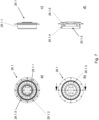
- a beneficial feature of the instant combustor 24 as disclosed herein is the design of the inner wall portion and the outer wall portion in the region of the nozzle at the rear and of the combustion chamber.
- the inner cross-sectional diameter of the inner space of the combustion chamber - as defined by the radial distance between the inner wall portion and the outer wall portion of the combustion chamber wall - initially decreases (narrows) towards the open end of the combustion chamber nozzle and ultimately widens again, thus causing a Venturi effect where radial distance between the inner wall portion and the outer wall portion is smallest.
- Keyhole shaped orifices (holes) 24.4.1 in the outer wall portion 24.2.3 allow entering of compressed air in the nozzle area of the combustion chamber 24.1.
- the entering of compressed air as promoted by the Venturi effect caused by the particular shape of the inner wall portion 24.2.1 and the outer wall portion 24.2.3 in the area of the combustion chamber annular nozzle portion 24.3.
- the desired effect is improved by the design of the inner wall portion 24.2.1 of the combustion chamber wall 24.2.
- the distance of the inner wall portion 24.2.1 from the longitudinal axis of the gas turbine assembly 20 initially increases in the direction of a combustion gas flow and then decreases again thus defining an apex 24.6.
- the Venturi effect is promoted.
- the additional air sucked into the nozzle portion 24.3 of the combustion chamber 24.1 due to the Venturi effect increases the mass flow of air exiting the combustion chamber 24.1 and streaming to the nozzle guide vane 26.1 of the gas turbine stage 26.
- This is achieved by the shape of the inner wall portion 24.2.1 and the outer wall portion 24.2.3.
- the shape provides that the inner cross-sectional diameter of the annular inner space of the combustion chamber 24.1 initially decreases (narrows) towards the open end of the combustion chamber nozzle 24.3 and ultimately widens again, thus causing the aforementioned Venturi effect where the radial distance between the inner wall portion 24.2.1 and the outer wall portion 24.2.3 is smallest.
- the Venturi effect created by the annular Venturi nozzle's portion of the combustion chamber improves the mass flow exiting from the combustion chamber and is fed to the axial turbine of the gas turbine assembly, thus improving the efficiency of the gas turbine assembly 20.
- the preferred shape of the combustion chamber's annular nozzle portion 24.3 preferably is achieved by varying the distance of the inner wall portion 24.2.1 from a longitudinal axis of the gas turbine assembly 20 along the longitudinal axis of the gas turbine assembly 20. The distance initially increases in the direction of a combustion gas flow and then decreases again thus defining an apex 24.6 that together with the outer wall portion 24.2.3 of the combustion chamber wall 24.2 defines the Venturi nozzle 24.7.6 for accelerating the hot combustion exhaust gases and for causing a reduced static pressure in the inner space 24.5 close to the combustion chamber annular nozzle 24.3.
- the combustion chamber 24.1 is surrounded by the open space 23 that during operation is filled with compressed air. Where the outer wall portion 24.2.3 narrows towards to an open end of the annular nozzle portion 24.3 of the combustion chamber 24.1, orifices or holes 24.4.1 are provided. The holes 24.4.1 are placed where during operation a reduced static pressure exists in the inner space 24.5, thus allowing air entering from the surrounding open space 23 into the inner space 24.5 and increasing the mass flow of the hot combustion gases exiting the combustion chamber 24.1. This improves the efficiency of the gas turbine assembly.
- the holes 24.4.1 provided in the narrowing outer wall portion 24.2.3 have a keyhole shape.
- the outer wall portion 24.2.3 comprises a generally cylindrical sub-portion 24.2.4 in which an annular vortex generating protrusion 24.2.5 is arranged, that protrudes into the inner space 24.5 enclosed by the combustion chamber wall 24.2.
- the annular vortex generating protrusion 24.2.5 improves mixing of fuel and compressed air and provides for an equal and complete combustion, thus improving the efficiency of the gas turbine assembly.
- the annular vortex generating protrusion 24.2.5 comprises an upstream wall portion 24.2.6 facing towards the fuel injection nozzles 24.7 and a downstream wall portion 24.2.7 facing away from the fuel injection nozzles 24.7.
- the vortex generating holes 24.4.2 are arranged in the downstream wall portion 24.2.7. This further improves the efficiency of the gas turbine assembly.
- the inner wall portion 24.2.1 comprises a frusto-conical shaped wall sub-portion 24.2.8 with a diameter that increases towards the annular Venturi nozzles portion 24.3 of the combustion chamber 24.1.
- the frusto-conical shaped wall sub-portion 24.2.8 provides that the annular free space between the inner wall portion 24.2.1 and the outer wall portion 24.2.3 decreases, thus causing an acceleration of the hot combustion gases during operation and a decreasing static pressure in the annular free space between the inner wall portion 24.2.1 and the outer wall portion 24.2.3.
- the frusto-conical shaped wall sub-portion 24.2.8 of the inner wall portion 24.2.1 is provided with holes 24.4 allowing compressed air from the surrounding open space 23 entering into the inner space 24.5.
- the holes 24.5 in the frusto-conical shaped wall sub-portion 24.2.8 of the inner wall portion 24.2.1 are arranged in eight rows along the longitudinal axis of the gas turbine assembly 20. The rows are equally spaced with respect to the circumferential direction of the frusto-conical shaped wall sub-portion 24.2.8. Each row comprises five holes 24.5 of different size and diameter, respectively.
- the combustor comprises four fuel injection nozzles 24.7 that are equally spaced from each other with respect to the circumferential direction of the cylindrical sub-portion 24.2.5.
- This arrangement of fuel injection nozzles supports producing a homogeneous stream of hot combustion gases for driving the axial gas turbine of the gas turbine assembly.
- the cylindrical sub-portion 24.2.5 of the outer wall portion 24.2.3 is provided with 4 openings 24.2.9 for mounting the fuel injection nozzles 24.7.
- the combustor 24 is provided with four fuel injection nozzles 24.7 equally spaced around the circumference of the front part of the combustion chamber.
- the combustor 24 is further provided with two spark plugs 24.8 that are arranged downstream of two of the fuel injection nozzles 24.7.
- a combustor 24 of a gas turbine assembly 20 typically is provided with multiple fuel injection nozzles 24.7 as shown in figures 8 to 10 .
- the fuel injection nozzles 24.7 are feeding the fuel, for instance kerosene, into the inner space of the combustion chamber 24.1.
- the main purpose of each fuel injection nozzle 24.7 is to vaporize the fuel that is injected into the combustion chamber 24.1 with high pressure.
- Fuel injection nozzles 24.7 may have a central fuel duct 24.7.1 that is surrounded by a coaxial air duct 24.7.2. Fuel is fed into a proximal end of the fuel duct 24.7.1 and can exit the fuel duct at a fuel nozzle 24.7.3 at the distal end of the fuel duct 24.7.1.
- a fuel injection nozzle 24.7 is provided with a fuel intake connector 24.7.4 and a fuel return connector 24.7.5 that both are connected to the proximal end of the fuel duct 24.7.1 for allowing the fuel to circulate and to supply several fuel injection nozzles 24.7 in series.
- the air duct 24.7.2 surrounding the fuel duct 24.7.1 provides that fuel exiting at a fuel nozzle 24.7.3 at the distal end of the fuel duct 24.7.1 is surrounded by an air stream that prevents the fuel from sticking to parts of the fuel injection nozzle 24.7.
- the fuel injection nozzle 24.7 of the instant turboprop engine 10 is provided with a Venturi nozzle 24.7.6 formed at the distal end of the air duct 24.7.2 surrounding the fuel nozzle 24.7.3 of the fuel duct 24.7.1.
- a baffle body 24.7.7 is arranged.
- the baffle body 24.7.7 has the shape of an inverted cone and is held by a pin 24.7.8 in the middle of the Venturi nozzle 24.7.6 at the distal orifice of the air duct 24.7.2.
- the baffle body 24.7.7 has a cone tip 24.7.9 facing away from the fuel nozzle 24.7.3 and a baffle face 24.7.10 facing towards the fuel nozzle 24.7.3.
- Venturi nozzle 24.7.6 for the fuel injector air stream in front of the fuel nozzle 24.7.3 of the fuel duct 24.7.1 combined with the baffle body 24.7.7 provides for an intense mixing of fuel and air, even if the fuel is injected with a lower pressure than usual.
- the air in the coaxial air duct 24.7.2 is enriched with 1% to 8% of hydrogen further improving the mixture provided by the fuel injection nozzle 24.7.
- pressurized fuel is expelled from the central fuel duct 24.7.1 inside the fuel injector 24.7, hitting the backface of the baffle body 24.7.7 that splits the fuel drops into smaller fuel drops.
- the stream of fuel drops expelled from the central fuel duct 24.7.1 is directed through the Venturi nozzle 24.7.6 of the coaxial air duct 24.7.2. Due to the Venturi nozzle 24.7.6 and the inverted cone shape of the baffle body 24.7.7 arranged inside the air duct 24.7.2 in front of the fuel duct 24.7.1 of the fuel injection nozzle 24.7, a pressurized fuel stream with small fuel drops coming out of the fuel injection nozzle 24.7 is achieved even if the fuel pressure is low.
- the baffle body 24.7.7 - preferably shaped as an inverted cone - together with the Venturi shape of the air duct's Venturi nozzle 24.7.6 surrounding the baffle body 24.7.7 in front of the fuel duct nozzle 24.7.3 causes a Venturi effect that accelerates the stream of air mixed with fuel. This further improves vaporization of the fuel.
- the reduced fuel pressure in the fuel duct 24.7.1 results in less fuel being injected into the combustion chamber 24. While this generally improves the efficiency, it also leads to less power provided by the combusted mixture of fuel and air. Adding a small amount of hydrogen to the mixture does not increase the temperature of the combusted fuel mixture but makes the combustion 60% more clean than a prior art combustion.
- the Venturi nozzle 24.7.6 with the baffle body 24.7.7 in front of the fuel nozzle 24.7.3 of the fuel duct 24.7.1 improves mixing of the fuel with air even at lower fuel pressures. Additionally adding some amount of hydrogen makes the combustion cleaner and thus reduces air pollution. In combination, a lower fuel consumption and less pollution is achieved by means of the novel fuel injection nozzle 24.7.
- the novel fuel injection nozzle 24.7 is used in a combustor 24 as disclosed above.
- the fuel injection nozzle 24.7 already provides a very good mixing of fuel and air and thus reduces or eliminates the need for causing vortices in the inner space of the combustion chamber 24.1. This in turn improves the efficiency of the combustion chamber 24.1.
- the overall efficiency of the novel combustor 24 with the novel fuel injection nozzle 24.7 is further improved by the design of the combustion chamber nozzle 24.3 that increases the mass stream exiting the combustion chamber 24.1 by drawing air into the combustion chamber nozzle 24.3 as the result of a Venturi effect achieved by the shape of the exhaust nozzle 24.3 of the combustion chamber 24.1.
- both, the particular combustion chamber and the particular fuel injection nozzle can be used separately and implemented independent from each other in different gas turbine engines.
- the instant combustion chamber has a unique design in the general inside shape that uses the inner and external ring to generate a Venturi effect to accelerate the flow to the exit of the combustion chamber making a high-pressure flow of the combustion to be used more efficiently.
- the gas turbine assembly 20 comprises the compressor 22, the combustor 24 and the axial gas turbine 26.
- Gas turbine 26 of gas turbine assembly 20 is a single stage axial gas turbine. Accordingly, gas turbine 26 comprises one static nozzle guide vane assembly 26.1 and one turbine wheel 26.2 that rotates during operation of gas turbine 26. Turbine wheel 26.2 is connected to the turbine shaft 28 that is also connected to the centrifugal impeller 22.1 of compressor 22. Thus, gas turbine 26 can drive the compressor 22. Turbine shaft 28 further is connected to the main shaft 30 to which the propeller 12 is mounted. The drive train from the turbine shaft 28 to the main shaft 30 comprises the helical reduction gearing 40, the centrifugal clutch 34 and the planetary reduction gear 32. The turbine shaft 28 is operatively connected to the centrifugal clutch 34 by the helical reduction gearing 40.
- the helical reduction gearing 40 comprises a pinion on the turbine shaft 28 and a main gear that is driven by the pinion.
- An input assembly of the centrifugal clutch 34 is connected to the main gear of the helical reduction gearing 40.
- the centrifugal clutch 34 provides that turbine shaft 28 only drives the planetary reduction gear 32 and thus propeller 12 if the rotation speed of the gas turbine assembly 20 is high enough.
- the flow characteristics of the gas turbine 26 are carefully matched with those of the compressor 22 and the combustor 24 to obtain a maximum efficiency and performance of the gas turbine assembly 20 during operation.
- the nozzle guide vane 26.1 would allow to lower maximum flow, then a back pressure would build up causing the compressor 22 to surge.
- too high flow through the nozzle guide vane 26.1 might cause the compressor to choke. In either condition a loss of efficiency very rapidly occurs.
- the guide blades 26.1.3 of nozzle guide vane 26.1 have a cross section corresponding to an airfoil shape. Passages between adjacent guide blades 26.1.3 form a convergent duct.
- the guide blades 26.1.3 are arranged between the outer ring 26.1.1 and the inner ring 26.1.2 in a manner that allows for expansion of the hot combustion gases flowing between the guide blades 26.1.3.
- the turbine blades 26.2.1 also have cross sections with an airfoil shape.
- the turbine blades 26.2.1 are designed to provide passages between adjacent turbine blades 26.2.1 that give a steady acceleration of the flow of hot combustion gases up to where the area between the turbine blades 26.2.1 is smallest and the velocity of the hot combustion gases is high enough as required at the exit to produce the required degree of reaction.
- the axial gas turbine 26 comprises an improved nozzle guide vane 26.1 that directs the stream of hot combustion gases towards turbine blades of turbine wheel 26.2.
- the axial gas turbine 26 has a single turbine stage, i.e. only one turbine wheel.
- the improved nozzle guide vane 26.1 comprises an outer ring 26.1.1, an inner ring 26.1.2 and guide blades 26.1.3 extending between the inner ring 26.1.2 and the outer ring 26.1.1 in a radial direction; see figures 6 and 7 .
- the guide blades 26.1.3 of nozzle guide vane 26.1 redirect the flow of hot combustion gases coming out of the combustion chamber's annular nozzle 24.3 and gives a spin to the stream of hot combustion gases in the direction of the rotation of the turbine blades.
- the diameter of the feed gas passage 26.1.5 as defined by the inner wall 26.1.4 of the outer ring 26.1.1 initially decreases in the direction of flow of the hot combustion gases. This has the effect that the stream of hot combustion gases is accelerated prior to reaching the guide blades 26.3. This implies that the outer ring 26.1.1 protrudes with respect to the guide blades 26.1.3 against the direction of flow of the hot combustion gases.
- the longitudinal extension of the outer ring 26.1.1 - i.e. the extension of the outer ring in the direction of air flow or in the longitudinal direction of shaft 28 - is 1,5 to 3 times larger than the extension of the inner ring 26.1.2 and the extension of the guide blades 26.1.3 in the longitudinal direction. Accordingly, a longitudinal extension of the feed gas passage along a longitudinal axis of the gas turbine assembly is about 1,2 to 2,3 times of the extension of the guide blades of the nozzle guide vane along a longitudinal axis of the gas turbine assembly.
- the diameter of the inner wall portion of the outer ring 26.1.1 increases where the guide blades 26.1.3 contact the inner wall portion of the outer ring 26.1.1. Accordingly the inner wall of the outer ring 26.1.1 has a smallest inner diameter where hot combustion gases are hitting the guide blades 26.1.3 during operation of the gas turbine 26.
- An outer diameter of an outer wall portion of the inner ring 26.1.2 decreases where the guide blades 26.1.3 contact the outer wall portion of the inner ring 26.1.2.
- the distance between the outer wall 26.1.6 of the inner ring 26.1.2 and the inner wall 26.1.4 of the outer ring 26.1.1 increases in the direction of gas flow where the guide blades 26.1.3 are arranged. This improves the efficiency of the gas turbine 26 because it reduces losses caused by the nozzle guide vane 26.1.
- the outer ring 26.1.1, the guide blades 26.1.3 and the inner ring 26.1.2 are an integral part made of metal.
- the nozzle guide vane 26.1 comprises 20 guide blades 26.1.3.
- the number of nozzle guide blades preferably is different from the number of turbine blades 26.2.1 of the turbine wheel 26.2.
- the inner diameter of the inner wall portion of the outer ring 26.1.1 at the entrance of the feed gas passage 26.1.5 corresponds to an outer diameter of the annular exhaust nozzle 24.3 of the combustion chamber 24.1 of the combustor 24 at the exit of the annular exhaust nozzle 24.3.
- the inner diameter of the inner wall portion of the outer ring at the entrance of the feed gas passage preferably is between 140 mm and 170 mm, for instance 155 mm.
- an improved fuel injection nozzle 24.7 and an improved combustion chamber 24.1 are provided.
- an improved nozzle guide vane 26.1 and a self-lubricating turbine main shaft 28 are provided. These improvements may be implemented independently from each other, i.e. the improved fuel injection nozzle or the improved combustion chamber or the improved nozzle guide vane or the self-lubricating turbine main shaft or a combination thereof may be implemented with any known or future gas turbine engine.
Landscapes
- Engineering & Computer Science (AREA)
- Chemical & Material Sciences (AREA)
- Combustion & Propulsion (AREA)
- Mechanical Engineering (AREA)
- General Engineering & Computer Science (AREA)
Priority Applications (2)
| Application Number | Priority Date | Filing Date | Title |
|---|---|---|---|
| EP23208331.1A EP4553387A1 (de) | 2023-11-07 | 2023-11-07 | Kraftstoffeinspritzdüse für eine gasturbine und gasturbine |
| PCT/EP2024/081449 WO2025099134A1 (en) | 2023-11-07 | 2024-11-07 | Fuel injection nozzle for a gas turbine engine and gas turbine engine |
Applications Claiming Priority (1)
| Application Number | Priority Date | Filing Date | Title |
|---|---|---|---|
| EP23208331.1A EP4553387A1 (de) | 2023-11-07 | 2023-11-07 | Kraftstoffeinspritzdüse für eine gasturbine und gasturbine |
Publications (1)
| Publication Number | Publication Date |
|---|---|
| EP4553387A1 true EP4553387A1 (de) | 2025-05-14 |
Family
ID=88745955
Family Applications (1)
| Application Number | Title | Priority Date | Filing Date |
|---|---|---|---|
| EP23208331.1A Withdrawn EP4553387A1 (de) | 2023-11-07 | 2023-11-07 | Kraftstoffeinspritzdüse für eine gasturbine und gasturbine |
Country Status (1)
| Country | Link |
|---|---|
| EP (1) | EP4553387A1 (de) |
Citations (5)
| Publication number | Priority date | Publication date | Assignee | Title |
|---|---|---|---|---|
| US20040083733A1 (en) * | 2002-11-05 | 2004-05-06 | Ingram Joe Britt | Fuel splashplate for microturbine combustor |
| US20100263382A1 (en) * | 2009-04-16 | 2010-10-21 | Alfred Albert Mancini | Dual orifice pilot fuel injector |
| US20150059346A1 (en) * | 2012-02-15 | 2015-03-05 | Snecma | Device for injecting air and fuel into a combustion chamber of a turbine engine |
| US20160209041A1 (en) * | 2013-10-07 | 2016-07-21 | United Technologies Corporation | Fuel vaporizer for a turbine engine combustor |
| US20190212009A1 (en) * | 2018-01-09 | 2019-07-11 | General Electric Company | Jet Swirl Air Blast Fuel Injector for Gas Turbine Engine |
-
2023
- 2023-11-07 EP EP23208331.1A patent/EP4553387A1/de not_active Withdrawn
Patent Citations (5)
| Publication number | Priority date | Publication date | Assignee | Title |
|---|---|---|---|---|
| US20040083733A1 (en) * | 2002-11-05 | 2004-05-06 | Ingram Joe Britt | Fuel splashplate for microturbine combustor |
| US20100263382A1 (en) * | 2009-04-16 | 2010-10-21 | Alfred Albert Mancini | Dual orifice pilot fuel injector |
| US20150059346A1 (en) * | 2012-02-15 | 2015-03-05 | Snecma | Device for injecting air and fuel into a combustion chamber of a turbine engine |
| US20160209041A1 (en) * | 2013-10-07 | 2016-07-21 | United Technologies Corporation | Fuel vaporizer for a turbine engine combustor |
| US20190212009A1 (en) * | 2018-01-09 | 2019-07-11 | General Electric Company | Jet Swirl Air Blast Fuel Injector for Gas Turbine Engine |
Similar Documents
| Publication | Publication Date | Title |
|---|---|---|
| US7878000B2 (en) | Pilot fuel injector for mixer assembly of a high pressure gas turbine engine | |
| KR100378566B1 (ko) | 가스터어빈엔진및그작동방법 | |
| US7581396B2 (en) | Mixer assembly for combustor of a gas turbine engine having a plurality of counter-rotating swirlers | |
| US3722216A (en) | Annular slot combustor | |
| JP4997018B2 (ja) | 一次燃料噴射器及び複数の二次燃料噴射ポートを有するガスタービンエンジン燃焼器のミキサ組立体のためのパイロットミキサ | |
| CN113357669B (zh) | 燃料喷射器流动装置 | |
| KR102071324B1 (ko) | 연소기용 노즐, 연소기 및 이를 포함하는 가스 터빈 | |
| EP1808644A2 (de) | Nachbrenner mit Hohlraum zum Erzeugen eingeschlossener Wirbel | |
| US8024931B2 (en) | Combustor for turbine engine | |
| US12486982B2 (en) | Combustor having a main chamber and one or more trapped vortex cavities | |
| JP2006105138A (ja) | ガスタービンエンジンを組み立てるための方法及び装置 | |
| KR20190109955A (ko) | 연소기용 노즐, 연소기 및 이를 포함하는 가스 터빈 | |
| KR20190136383A (ko) | 연소기용 노즐, 연소기 및 이를 포함하는 가스 터빈 | |
| CN118168029A (zh) | 旋转爆震实现的增强器系统 | |
| US6981366B2 (en) | Turbineless jet engine | |
| KR20190101554A (ko) | 연소기용 노즐, 연소기 및 이를 포함하는 가스 터빈 | |
| EP4553387A1 (de) | Kraftstoffeinspritzdüse für eine gasturbine und gasturbine | |
| EP4553388A1 (de) | Brennkammer für eine gasturbine und gasturbine | |
| EP4553276A1 (de) | Gasturbine und turboproptriebwerk | |
| CN115046225A (zh) | 燃烧室头部、燃烧室和航空发动机 | |
| WO2025099134A1 (en) | Fuel injection nozzle for a gas turbine engine and gas turbine engine | |
| WO2025099131A1 (en) | Combustion chamber for a gas turbine engine and gas turbine | |
| CA2597846A1 (en) | Pilot fuel injector for mixer assembly of a high pressure gas turbine engine | |
| US10837369B2 (en) | Igniter assembly for a gas turbine combustor | |
| EP4553294A1 (de) | Hauptwelle eines gasturbinentriebwerks und gasturbinentriebwerk |
Legal Events
| Date | Code | Title | Description |
|---|---|---|---|
| PUAI | Public reference made under article 153(3) epc to a published international application that has entered the european phase |
Free format text: ORIGINAL CODE: 0009012 |
|
| STAA | Information on the status of an ep patent application or granted ep patent |
Free format text: STATUS: THE APPLICATION HAS BEEN PUBLISHED |
|
| AK | Designated contracting states |
Kind code of ref document: A1 Designated state(s): AL AT BE BG CH CY CZ DE DK EE ES FI FR GB GR HR HU IE IS IT LI LT LU LV MC ME MK MT NL NO PL PT RO RS SE SI SK SM TR |
|
| STAA | Information on the status of an ep patent application or granted ep patent |
Free format text: STATUS: THE APPLICATION IS DEEMED TO BE WITHDRAWN |
|
| 18D | Application deemed to be withdrawn |
Effective date: 20251115 |