EP4553404A1 - Crochet de toit - Google Patents
Crochet de toit Download PDFInfo
- Publication number
- EP4553404A1 EP4553404A1 EP24211359.5A EP24211359A EP4553404A1 EP 4553404 A1 EP4553404 A1 EP 4553404A1 EP 24211359 A EP24211359 A EP 24211359A EP 4553404 A1 EP4553404 A1 EP 4553404A1
- Authority
- EP
- European Patent Office
- Prior art keywords
- roof
- support
- hook
- base
- mounting
- Prior art date
- Legal status (The legal status is an assumption and is not a legal conclusion. Google has not performed a legal analysis and makes no representation as to the accuracy of the status listed.)
- Pending
Links
Images


Classifications
-
- F—MECHANICAL ENGINEERING; LIGHTING; HEATING; WEAPONS; BLASTING
- F24—HEATING; RANGES; VENTILATING
- F24S—SOLAR HEAT COLLECTORS; SOLAR HEAT SYSTEMS
- F24S25/00—Arrangement of stationary mountings or supports for solar heat collector modules
- F24S25/60—Fixation means, e.g. fasteners, specially adapted for supporting solar heat collector modules
- F24S25/61—Fixation means, e.g. fasteners, specially adapted for supporting solar heat collector modules for fixing to the ground or to building structures
- F24S25/613—Fixation means, e.g. fasteners, specially adapted for supporting solar heat collector modules for fixing to the ground or to building structures in the form of bent strips or assemblies of strips; Hook-like connectors; Connectors to be mounted between building-covering elements
-
- F—MECHANICAL ENGINEERING; LIGHTING; HEATING; WEAPONS; BLASTING
- F24—HEATING; RANGES; VENTILATING
- F24S—SOLAR HEAT COLLECTORS; SOLAR HEAT SYSTEMS
- F24S25/00—Arrangement of stationary mountings or supports for solar heat collector modules
- F24S25/30—Arrangement of stationary mountings or supports for solar heat collector modules using elongate rigid mounting elements extending substantially along the supporting surface, e.g. for covering buildings with solar heat collectors
-
- F—MECHANICAL ENGINEERING; LIGHTING; HEATING; WEAPONS; BLASTING
- F24—HEATING; RANGES; VENTILATING
- F24S—SOLAR HEAT COLLECTORS; SOLAR HEAT SYSTEMS
- F24S25/00—Arrangement of stationary mountings or supports for solar heat collector modules
- F24S25/60—Fixation means, e.g. fasteners, specially adapted for supporting solar heat collector modules
- F24S25/61—Fixation means, e.g. fasteners, specially adapted for supporting solar heat collector modules for fixing to the ground or to building structures
-
- F—MECHANICAL ENGINEERING; LIGHTING; HEATING; WEAPONS; BLASTING
- F24—HEATING; RANGES; VENTILATING
- F24S—SOLAR HEAT COLLECTORS; SOLAR HEAT SYSTEMS
- F24S25/00—Arrangement of stationary mountings or supports for solar heat collector modules
- F24S25/70—Arrangement of stationary mountings or supports for solar heat collector modules with means for adjusting the final position or orientation of supporting elements in relation to each other or to a mounting surface; with means for compensating mounting tolerances
-
- H—ELECTRICITY
- H02—GENERATION; CONVERSION OR DISTRIBUTION OF ELECTRIC POWER
- H02S—GENERATION OF ELECTRIC POWER BY CONVERSION OF INFRARED RADIATION, VISIBLE LIGHT OR ULTRAVIOLET LIGHT, e.g. USING PHOTOVOLTAIC [PV] MODULES
- H02S20/00—Supporting structures for PV modules
- H02S20/20—Supporting structures directly fixed to an immovable object
- H02S20/22—Supporting structures directly fixed to an immovable object specially adapted for buildings
- H02S20/23—Supporting structures directly fixed to an immovable object specially adapted for buildings specially adapted for roof structures
-
- F—MECHANICAL ENGINEERING; LIGHTING; HEATING; WEAPONS; BLASTING
- F24—HEATING; RANGES; VENTILATING
- F24S—SOLAR HEAT COLLECTORS; SOLAR HEAT SYSTEMS
- F24S25/00—Arrangement of stationary mountings or supports for solar heat collector modules
- F24S2025/01—Special support components; Methods of use
- F24S2025/014—Methods for installing support elements
-
- F—MECHANICAL ENGINEERING; LIGHTING; HEATING; WEAPONS; BLASTING
- F24—HEATING; RANGES; VENTILATING
- F24S—SOLAR HEAT COLLECTORS; SOLAR HEAT SYSTEMS
- F24S25/00—Arrangement of stationary mountings or supports for solar heat collector modules
- F24S25/60—Fixation means, e.g. fasteners, specially adapted for supporting solar heat collector modules
- F24S2025/6003—Fixation means, e.g. fasteners, specially adapted for supporting solar heat collector modules by clamping
Definitions
- the invention relates to a roof hook for fastening a mounting unit, preferably a mounting rail, to a roof structure and/or to a roof element, comprising a base support for fastening the roof hook to the roof structure and/or to the roof element and a support, preferably a rail support, with a mounting section for fastening the mounting unit to the roof hook.
- Roof hooks are generally familiar. They are used, for example, for mounting solar panels and/or photovoltaic modules.
- the solar panels and/or photovoltaic modules are mounted, for example, on mounting rails, which are also called support rails.
- the roof hooks are attached to the base support, e.g. to roof structures, for example to the substructures of pitched roofs.
- a disadvantage of existing roof hooks is that the entire load is absorbed by the base support. This can negatively impact the statics, especially if the roof hook is bent.
- the roof hook is designed and/or can be used for fastening a mounting unit to a roof structure and/or to a roof element.
- the mounting unit can, for example, be a mounting rail and/or a support element.
- the roof structure for example the roof substructure, can consist of beams and/or rafters.
- the roof element can be, for example, a roof tile, a roof shingle and/or a sheet of metal.
- a solar panel and/or photovoltaic module can be mounted on the mounting rail, which is also called a support rail.
- the roof hook has a base support for attaching the roof hook to the roof structure and/or the roof element.
- a base support of the roof hook can comprise, for example, a plate-shaped base with recesses.
- the base can be attached to the roof structure, e.g., by screwing, using screws and/or bolts.
- the roof hook has a support, preferably a rail support, with a mounting section for attaching the mounting unit to the roof hook.
- the roof hook can be designed as a profile.
- the profile can, for example, have a rectangular cross-sectional area.
- the roof hook comprises or consists of a metal material, e.g. an aluminum material.
- the support can be connected or is connected to the base support at a fixing section that is height-adjustable.
- any unevenness in the roof structure and/or the roof elements must be compensated for.
- the height adjustability allows the distance between the mounting unit and the roof structure and/or the roof element to be adjusted.
- the support can be movable relative to the base support.
- the fixing section and/or the base support can have an elongated hole. Fixation in the desired position can preferably be achieved by means of a screw.
- the base support and/or the fixing section can have a screw receptacle, e.g., a recess with a thread.
- the height is adjusted so that the support rests on the roof element.
- the support e.g., the fixing section
- the support can be inclined in one direction. This allows for optimal adaptation to the roof element. Damage to the roof element, such as tile breakage, can be avoided.
- the support has a support for resting on the roof element.
- the support can be used to exert pressure on the roof element when adjusted to the appropriate height. This ensures that the roof element is securely held in place. Furthermore, the fact that the roof hook rests on the roof element in the area of the support distributes the loads and improves the overall structural properties.
- the base support has a bracket and a hook which are connectable or connected to each other.
- the base support is therefore designed in at least two parts.
- the bracket and the hook are oriented parallel to each other at least in sections.
- the roof element can be held between the bracket and the hook.
- the base support encompasses at least a portion of the roof element.
- the hook can preferably be L-shaped.
- the hook can have a base and a fastening area that extends at least partially perpendicular to the base.
- the base can preferably be designed as a plate with plate recesses.
- the base can be attached, e.g., screwed, to the plate recesses, for example, using screws and/or bolts to the roof structure.
- the hook has one or more ridges on the side facing the bracket. This allows for a secure grip on the underside of the roof element.
- the bracket and hook are preferably connected or connectable via a plug-in and/or screw connection. This ensures a secure hold.
- the bracket and hook are height-adjustable and connectable. This allows for adaptation to roof elements of varying thicknesses.
- the maximum adjustment range i.e. the maximum distance between the bracket and the hook, in particular a base of the hook, can be between 2 cm and 10 cm, preferably between 3 cm and 7 cm, e.g. between 3.6 cm and 6.1 cm.
- the support can be connected or attached to the bracket in a height-adjustable manner.
- the bracket can thus be connected or attached to the support's fixing section on one side and to the hook on the other.
- a one-part base support is also conceivable.
- a screw is provided for fixing the support to the base support.
- the screw can engage in a slotted hole and be screwed into a screw receptacle.
- a fixing area of the base support facing the fixing section can be oriented parallel to the fixing section.
- the fixing section and/or the fixing area can have one or more ribbings. This can improve the grip.
- the fixing section and the mounting section enclose an angle between 100° and 180°, preferably between 120° and 170°.
- the angle can be between 155° and 160°.
- the fixing section can be angled relative to the mounting section.
- the angle can be equal to or less than 180°.
- the fixing section and the support enclose an angle between 20° and 160°, preferably between 50° and 130°.
- the angle can be between 65° and 70°.
- the support can be angled relative to the fixing section.
- the angle can be equal to or less than 90°.
- the support can be oriented perpendicular to the mounting section.
- the fixing section extends centrally from the support.
- the pressure on the roof element can thus be distributed evenly.
- the support is rectangular.
- the pressure on the roof element can be distributed evenly.
- the support comprises a friction-enhanced material and/or a friction-enhanced structure.
- the friction-enhanced material can, for example, be a rubber material.
- the friction-enhanced structure can, for example, have or consist of one or more corrugations.
- the support has a support body and a rubber base as a friction-enhancing material.
- the support is preferably at least or exactly two-part.
- the rubber pad is arranged at least in sections on the underside of the support body.
- the underside of the support is thus formed by the friction-enhanced material, which preferably has corrugations.
- the rubber pad can be attached to the support body, preferably without the use of tools. For example, it can be clipped onto the support body.
- the rubber pad can wrap around the sides of the support body for this purpose.
- the rubber base can have a U-shaped cross-section.
- the invention also relates to a fastening method, i.e. a method for fastening a roof hook according to the invention to a roof structure and/or to a roof element.
- the base support is mounted, for example screwed, to the roof structure and/or to the roof element.
- the height between the bracket and the hook can be adjusted.
- These components can be fixed in the desired position, e.g., with a screw.
- the height of the support is adjusted relative to the base support so that the support rests on the roof element.
- the support exerts pressure on the roof element and/or at least carries part of the load.
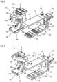
- Fig. 1 shows a roof hook for fastening a mounting unit 10, preferably a mounting rail, shown in dashed lines, to a roof element 46.
- the roof hook has a base support 14 with a bracket 16 and a hook 18 for fastening the roof hook to the roof element 46.
- the bracket 16 is connected to the hook 18 in a height-adjustable manner.
- the hook 18 has a plate-shaped base 20 and a fastening area 22 extending perpendicularly from the base 20.
- the fastening area 22 has a slot 24 for receiving the bracket 16.
- the bracket 16 has a bracket body 17 oriented substantially parallel to the base 20 and a bracket section 25 angled at a right angle thereto. The angled bracket section 25 is inserted into the slot 24.
- fixation can be achieved using a screw 26.
- a support device 27 of the bracket 16 supports the bracket 16 and prevents it from tipping over.
- the fastening area 22 can have a recess for a screw 26 on each of the opposite sides of the slot 24.
- the screw 26 for fixing the bracket 16 can be fastened to one recess, which can have a thread, for example.
- a terminal 28 of a grounding device 30 can optionally be fastened to the other recess, which can have a thread, for example, via a screw 26.
- the roof hook has a support, preferably a rail support 32, with a mounting section 34 for fastening the mounting unit 10 to the roof hook.
- the mounting unit 10 can be clamped to the mounting section 34 of the carrier 32, for example, via a clamping device 36.
- the clamping device 36 has a clamping body 38 and a clamping element designed as a screw 40.
- the support 32 is connected to a fixing section 42 in a height-adjustable manner to a fixing area 43 of the base support 14.
- a screw 26 can be used for fixing.
- the fixing section 42 is preferably angled relative to the mounting section 34, e.g. by an angle W of 157°.
- the support 32 has a support 44 for resting on the roof element 46.
- the fixing section 42 can extend centrally from the support 44 at an angle W' of, for example, 65°.
- the fixing section 42 has an elongated hole 47 into which the screw 26 can engage.
- the support 44 has a support body 48 and a rubber base 50.
- the rubber base 50 can have a ribbing on its underside.
- the plate-shaped base 20 can have plate recesses 52.
- the base 20 can be fastened, e.g., screwed, to a roof structure 12 at the plate recesses 52, for example by means of screws and/or bolts.
- the plate-shaped base 20 has several ridges 54 on a side facing the bracket 16. These provide a secure grip on the underside of the roof element 46.
- the clamping device 36 with the clamping body 38 and the clamping element designed as a screw 40 is fastened in a first position for horizontal attachment of the mounting unit 10 to the mounting section 34.
- Fig. 4 the clamping device 36 is fastened in a second position offset by 90° (with respect to a vertical axis V) relative to the first position for the inclined attachment of the mounting unit 10 to the mounting section 34.
- Inclined here means a direction parallel to or along the roof slope, e.g., toward the ridge. Inclined installation is preferably perpendicular to the horizontal installation.
- the roof can be equipped with either only horizontal or only inclined mounting units.
- a combination of horizontal and inclined mounting units is possible, known as a cross-connection.
- the clamping device 36 can also be rotated by 180° (relative to a horizontal plane) in the second position.
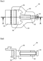
- the clamping device 36 has a clamping body 38 which completely encloses a recess 56 for receiving the mounting section 34.
- the recess 56 has a first receiving slot 58 and a second receiving slot 60 offset by 90° relative to the first receiving slot 58.
- the first receiving slot 58 and the second receiving slot 60 are connected to each other.
- the second receiving slot 60 extends centrally from the first receiving slot 58.
- the clamping body 38 has a clamping element recess 62 for the clamping element 40, which opens into the second receiving slot 60.
- the clamping element 40 is at least as long as the difference between the longitudinal extent of the second receiving slot 60 including the clamping element recess 62 and the thickness of the (in Fig. 5 not shown) assembly section 34.
- the clamping element 40 is also longer than the longitudinal extent of the first receiving slot 58 or than the longitudinal extent of the second receiving slot 60.
- Fig. 6 a sectional view of the clamping device 36 is shown.
- a holding structure 64 of the clamping device 36 can be firmly, preferably non-detachably, connected to the clamping body 38.
- the holding structure 64 can be formed as a separate component.
- the clamping device 36 can be rotated by 180° (relative to a horizontal plane). This also changes the orientation of the support structure 64.
- the orientation of the support structure 64 is preferably the same in the first position and the second position.
- Fig. 7 shows a roof hook for fastening a mounting unit 10 to a roof structure 12.
- Hook 18 is opposite Fig. 1 offset by 180° and screwed to the base 20 with the roof structure 12.
Landscapes
- Engineering & Computer Science (AREA)
- Chemical & Material Sciences (AREA)
- Mechanical Engineering (AREA)
- Sustainable Development (AREA)
- Sustainable Energy (AREA)
- Thermal Sciences (AREA)
- Physics & Mathematics (AREA)
- Combustion & Propulsion (AREA)
- Life Sciences & Earth Sciences (AREA)
- General Engineering & Computer Science (AREA)
- Architecture (AREA)
- Civil Engineering (AREA)
- Structural Engineering (AREA)
- Roof Covering Using Slabs Or Stiff Sheets (AREA)
- Fittings On The Vehicle Exterior For Carrying Loads, And Devices For Holding Or Mounting Articles (AREA)
Applications Claiming Priority (1)
| Application Number | Priority Date | Filing Date | Title |
|---|---|---|---|
| DE102023131545.5A DE102023131545A1 (de) | 2023-11-13 | 2023-11-13 | Dachhaken |
Publications (1)
| Publication Number | Publication Date |
|---|---|
| EP4553404A1 true EP4553404A1 (fr) | 2025-05-14 |
Family
ID=93456026
Family Applications (1)
| Application Number | Title | Priority Date | Filing Date |
|---|---|---|---|
| EP24211359.5A Pending EP4553404A1 (fr) | 2023-11-13 | 2024-11-07 | Crochet de toit |
Country Status (2)
| Country | Link |
|---|---|
| EP (1) | EP4553404A1 (fr) |
| DE (1) | DE102023131545A1 (fr) |
Citations (3)
| Publication number | Priority date | Publication date | Assignee | Title |
|---|---|---|---|---|
| EP1808650A2 (fr) * | 2005-12-21 | 2007-07-18 | Robert Bosch Gmbh | Crochet de toiture |
| EP3493397A1 (fr) * | 2017-11-29 | 2019-06-05 | Allimex | Dispositif de montage de panneaux solaires |
| EP3361183B1 (fr) * | 2017-02-08 | 2019-12-18 | Esdec B.V. | Élément de stabilisation et procédé de stabilisation d'un crochet de toit par rapport à une tuile de toit |
Family Cites Families (1)
| Publication number | Priority date | Publication date | Assignee | Title |
|---|---|---|---|---|
| DE202007012304U1 (de) * | 2007-03-30 | 2007-12-27 | Wilhelm Flender Gmbh & Co. Kg | Befestigungsvorrichtung zur Befestigung von Bauteilen an geneigten Dächern |
-
2023
- 2023-11-13 DE DE102023131545.5A patent/DE102023131545A1/de active Pending
-
2024
- 2024-11-07 EP EP24211359.5A patent/EP4553404A1/fr active Pending
Patent Citations (3)
| Publication number | Priority date | Publication date | Assignee | Title |
|---|---|---|---|---|
| EP1808650A2 (fr) * | 2005-12-21 | 2007-07-18 | Robert Bosch Gmbh | Crochet de toiture |
| EP3361183B1 (fr) * | 2017-02-08 | 2019-12-18 | Esdec B.V. | Élément de stabilisation et procédé de stabilisation d'un crochet de toit par rapport à une tuile de toit |
| EP3493397A1 (fr) * | 2017-11-29 | 2019-06-05 | Allimex | Dispositif de montage de panneaux solaires |
Also Published As
| Publication number | Publication date |
|---|---|
| DE102023131545A1 (de) | 2025-05-15 |
Similar Documents
| Publication | Publication Date | Title |
|---|---|---|
| DE102012011969B4 (de) | Solarmodulhalter | |
| AT506230B1 (de) | Befestigungsvorrichtung für bauteile, insbesondere für solarkollektoren | |
| EP1826504B1 (fr) | Dispositif de fixation pour un profil de support | |
| DE102008015089B4 (de) | Befestigungsvorrichtung zur Befestigung von Bauteilen an geneigten Dächern | |
| EP2434229B1 (fr) | Crochet de toit pour le montage de modules solaires sur des toits | |
| WO2016198305A1 (fr) | Étrier de montage pour module photovoltaïque ainsi que système photovoltaïque | |
| WO2010124680A2 (fr) | Dispositif pour la fixation d'un rail porteur sur un crochet de toiture | |
| EP3623721B1 (fr) | Crochet de toit | |
| DE202023106645U1 (de) | Dachhaken | |
| EP3623722A1 (fr) | Crochet de toit | |
| WO2022242950A1 (fr) | Crochet de toit permettant la fixation d'éléments de support à une structure de toit, et procédé d'assemblage | |
| DE102004049595B3 (de) | Dachhaken | |
| EP2295894A2 (fr) | Agencement de fixation de modules d'un dispositif photovoltaïque ou de panneaux solaires | |
| DE202023106644U1 (de) | Dachhaken | |
| EP4411275B1 (fr) | Crochet de toit | |
| EP4553404A1 (fr) | Crochet de toit | |
| DE102004012412A1 (de) | Vorrichtung zur Befestigung von Solarkollektoren auf einem Dach | |
| EP2246646A2 (fr) | crochet de couvreur | |
| DE102023101686B4 (de) | Unterkonstruktion für Photovoltaik-Module auf dem Dach | |
| EP4553403A1 (fr) | Crochet de toit | |
| DE102023131549A1 (de) | Dachhaken | |
| DE202024100099U1 (de) | Befestigungsvorrichtung | |
| DE202023106646U1 (de) | Dachhaken | |
| EP1717384A1 (fr) | Fixation pour accessoires de toit | |
| EP1569279A2 (fr) | Support de toit pour modules solaires |
Legal Events
| Date | Code | Title | Description |
|---|---|---|---|
| PUAI | Public reference made under article 153(3) epc to a published international application that has entered the european phase |
Free format text: ORIGINAL CODE: 0009012 |
|
| STAA | Information on the status of an ep patent application or granted ep patent |
Free format text: STATUS: THE APPLICATION HAS BEEN PUBLISHED |
|
| AK | Designated contracting states |
Kind code of ref document: A1 Designated state(s): AL AT BE BG CH CY CZ DE DK EE ES FI FR GB GR HR HU IE IS IT LI LT LU LV MC ME MK MT NL NO PL PT RO RS SE SI SK SM TR |
|
| STAA | Information on the status of an ep patent application or granted ep patent |
Free format text: STATUS: REQUEST FOR EXAMINATION WAS MADE |
|
| 17P | Request for examination filed |
Effective date: 20251114 |