EP4553417A1 - Dispositif à cycle frigorifique - Google Patents
Dispositif à cycle frigorifique Download PDFInfo
- Publication number
- EP4553417A1 EP4553417A1 EP24804718.5A EP24804718A EP4553417A1 EP 4553417 A1 EP4553417 A1 EP 4553417A1 EP 24804718 A EP24804718 A EP 24804718A EP 4553417 A1 EP4553417 A1 EP 4553417A1
- Authority
- EP
- European Patent Office
- Prior art keywords
- refrigerant
- unit
- utilization
- shutoff valve
- control unit
- Prior art date
- Legal status (The legal status is an assumption and is not a legal conclusion. Google has not performed a legal analysis and makes no representation as to the accuracy of the status listed.)
- Pending
Links
Images


Classifications
-
- F—MECHANICAL ENGINEERING; LIGHTING; HEATING; WEAPONS; BLASTING
- F25—REFRIGERATION OR COOLING; COMBINED HEATING AND REFRIGERATION SYSTEMS; HEAT PUMP SYSTEMS; MANUFACTURE OR STORAGE OF ICE; LIQUEFACTION SOLIDIFICATION OF GASES
- F25B—REFRIGERATION MACHINES, PLANTS OR SYSTEMS; COMBINED HEATING AND REFRIGERATION SYSTEMS; HEAT PUMP SYSTEMS
- F25B13/00—Compression machines, plants or systems, with reversible cycle
-
- F—MECHANICAL ENGINEERING; LIGHTING; HEATING; WEAPONS; BLASTING
- F24—HEATING; RANGES; VENTILATING
- F24F—AIR-CONDITIONING; AIR-HUMIDIFICATION; VENTILATION; USE OF AIR CURRENTS FOR SCREENING
- F24F11/00—Control or safety arrangements
- F24F11/30—Control or safety arrangements for purposes related to the operation of the system, e.g. for safety or monitoring
- F24F11/32—Responding to malfunctions or emergencies
- F24F11/36—Responding to malfunctions or emergencies to leakage of heat-exchange fluid
-
- F—MECHANICAL ENGINEERING; LIGHTING; HEATING; WEAPONS; BLASTING
- F25—REFRIGERATION OR COOLING; COMBINED HEATING AND REFRIGERATION SYSTEMS; HEAT PUMP SYSTEMS; MANUFACTURE OR STORAGE OF ICE; LIQUEFACTION SOLIDIFICATION OF GASES
- F25B—REFRIGERATION MACHINES, PLANTS OR SYSTEMS; COMBINED HEATING AND REFRIGERATION SYSTEMS; HEAT PUMP SYSTEMS
- F25B41/00—Fluid-circulation arrangements
- F25B41/20—Disposition of valves, e.g. of on-off valves or flow control valves
- F25B41/24—Arrangement of shut-off valves for disconnecting a part of the refrigerant cycle, e.g. an outdoor part
-
- F—MECHANICAL ENGINEERING; LIGHTING; HEATING; WEAPONS; BLASTING
- F25—REFRIGERATION OR COOLING; COMBINED HEATING AND REFRIGERATION SYSTEMS; HEAT PUMP SYSTEMS; MANUFACTURE OR STORAGE OF ICE; LIQUEFACTION SOLIDIFICATION OF GASES
- F25B—REFRIGERATION MACHINES, PLANTS OR SYSTEMS; COMBINED HEATING AND REFRIGERATION SYSTEMS; HEAT PUMP SYSTEMS
- F25B49/00—Arrangement or mounting of control or safety devices
- F25B49/005—Arrangement or mounting of control or safety devices of safety devices
-
- F—MECHANICAL ENGINEERING; LIGHTING; HEATING; WEAPONS; BLASTING
- F25—REFRIGERATION OR COOLING; COMBINED HEATING AND REFRIGERATION SYSTEMS; HEAT PUMP SYSTEMS; MANUFACTURE OR STORAGE OF ICE; LIQUEFACTION SOLIDIFICATION OF GASES
- F25B—REFRIGERATION MACHINES, PLANTS OR SYSTEMS; COMBINED HEATING AND REFRIGERATION SYSTEMS; HEAT PUMP SYSTEMS
- F25B2313/00—Compression machines, plants or systems with reversible cycle not otherwise provided for
- F25B2313/023—Compression machines, plants or systems with reversible cycle not otherwise provided for using multiple indoor units
- F25B2313/0233—Compression machines, plants or systems with reversible cycle not otherwise provided for using multiple indoor units in parallel arrangements
-
- F—MECHANICAL ENGINEERING; LIGHTING; HEATING; WEAPONS; BLASTING
- F25—REFRIGERATION OR COOLING; COMBINED HEATING AND REFRIGERATION SYSTEMS; HEAT PUMP SYSTEMS; MANUFACTURE OR STORAGE OF ICE; LIQUEFACTION SOLIDIFICATION OF GASES
- F25B—REFRIGERATION MACHINES, PLANTS OR SYSTEMS; COMBINED HEATING AND REFRIGERATION SYSTEMS; HEAT PUMP SYSTEMS
- F25B2313/00—Compression machines, plants or systems with reversible cycle not otherwise provided for
- F25B2313/027—Compression machines, plants or systems with reversible cycle not otherwise provided for characterised by the reversing means
- F25B2313/02791—Compression machines, plants or systems with reversible cycle not otherwise provided for characterised by the reversing means using shut-off valves
-
- F—MECHANICAL ENGINEERING; LIGHTING; HEATING; WEAPONS; BLASTING
- F25—REFRIGERATION OR COOLING; COMBINED HEATING AND REFRIGERATION SYSTEMS; HEAT PUMP SYSTEMS; MANUFACTURE OR STORAGE OF ICE; LIQUEFACTION SOLIDIFICATION OF GASES
- F25B—REFRIGERATION MACHINES, PLANTS OR SYSTEMS; COMBINED HEATING AND REFRIGERATION SYSTEMS; HEAT PUMP SYSTEMS
- F25B2400/00—Component parts or details not otherwise provided for in this subclass
- F25B2400/04—Refrigeration circuit bypassing means
-
- F—MECHANICAL ENGINEERING; LIGHTING; HEATING; WEAPONS; BLASTING
- F25—REFRIGERATION OR COOLING; COMBINED HEATING AND REFRIGERATION SYSTEMS; HEAT PUMP SYSTEMS; MANUFACTURE OR STORAGE OF ICE; LIQUEFACTION SOLIDIFICATION OF GASES
- F25B—REFRIGERATION MACHINES, PLANTS OR SYSTEMS; COMBINED HEATING AND REFRIGERATION SYSTEMS; HEAT PUMP SYSTEMS
- F25B2500/00—Problems to be solved
- F25B2500/22—Preventing, detecting or repairing leaks of refrigeration fluids
- F25B2500/222—Detecting refrigerant leaks
Definitions
- the present disclosure relates to a refrigeration cycle apparatus.
- Patent Literature 1 JP 2020-030043 A
- one shutoff valve is provided between an indoor unit and a liquid pipe and between the indoor unit and a gas pipe.
- the air conditioning system of Patent Literature 1 closes the shutoff valve to shut off a flow of the refrigerant to the indoor unit and suppress a further leakage of the refrigerant in an air conditioning target space.
- shutoff valve having a large diameter is expensive and tends to cause an increase in manufacturing cost.
- An object of the present disclosure is to provide a refrigeration cycle apparatus capable of suppressing a leakage of a refrigerant in a utilization unit while suppressing an increase in manufacturing cost.
- a refrigeration cycle apparatus includes a utilization unit, a heat source unit, a gas-refrigerant connection pipe, and a first shutoff valve unit.
- the utilization unit includes a utilization heat exchanger.
- the heat source unit includes a compressor and a heat source heat exchanger.
- the gas-refrigerant connection pipe is provided between the compressor and the utilization heat exchanger.
- the first shutoff valve unit is provided between the gas-refrigerant connection pipe and the utilization unit, and shuts off a refrigerant flowing between the gas-refrigerant connection pipe and the utilization unit.
- the first shutoff valve unit includes a plurality of first dividing pipes through which the refrigerant flowing between the gas-refrigerant connection pipe and the utilization unit flows in parallel, and a shutoff valve provided in each of the plurality of first dividing pipes.
- the refrigeration cycle apparatus since the refrigerant flowing between the gas-refrigerant connection pipe and the utilization unit is divided into the plurality of first dividing pipes, the amount of the refrigerant passing through each of the shutoff valves is smaller than the amount of the refrigerant when the refrigerant is not divided. Therefore, the shutoff valve can be designed to be small, and an increase in a manufacturing cost associated with an increase in size of each shutoff valve is suppressed. As a result, the refrigeration cycle apparatus can suppress a leakage of the refrigerant in the utilization unit while suppressing an increase in the manufacturing cost.
- a refrigeration cycle apparatus is the refrigeration cycle apparatus according to the first aspect, and further includes a liquid-refrigerant connection pipe and a second shutoff valve unit.
- the liquid-refrigerant connection pipe is provided between the utilization heat exchanger and the heat source heat exchanger.
- the second shutoff valve unit is provided between the liquid-refrigerant connection pipe and the utilization unit, and shuts off the refrigerant flowing between the liquid-refrigerant connection pipe and the utilization unit.
- the second shutoff valve unit includes a plurality of second dividing pipes through which the refrigerant flowing between the liquid-refrigerant connection pipe and the utilization unit flows in parallel, and a plurality of shutoff valves provided in each of the second dividing pipes.
- the refrigeration cycle apparatus also includes the shutoff valve between the liquid-refrigerant connection pipe and the utilization unit, a leakage of the refrigerant in the utilization unit can be more effectively suppressed while an increase in the manufacturing cost is suppressed.
- a refrigeration cycle apparatus is the refrigeration cycle apparatus according to the first or second aspect, and further includes a control unit that controls the shutoff valves.
- the control unit closes all the shutoff valves that shut off the refrigerant flowing between the utilization unit in which a leakage of the refrigerant has been detected and the gas-refrigerant connection pipe or the liquid-refrigerant connection pipe.
- the refrigeration cycle apparatus can suppress the leakage of the refrigerant in the utilization unit.
- a refrigeration cycle apparatus is the refrigeration cycle apparatus according to any of the first to third aspects, in which the control unit includes a utilization unit control unit, a heat source unit control unit, and a shutoff valve control unit.
- the utilization unit control unit is provided in the utilization unit.
- the heat source unit control unit is provided in the heat source unit.
- the shutoff valve control unit controls the shutoff valves.
- the utilization unit control unit transmits a first signal to the heat source unit control unit.
- the heat source unit control unit transmits a second signal to the shutoff valve control unit.
- the shutoff valve control unit closes all the shutoff valves that shut off the refrigerant flowing between the utilization unit in which the leakage of the refrigerant has been detected and the gas-refrigerant connection pipe or the liquid-refrigerant connection pipe.
- the shutoff valve control unit closes all the corresponding shutoff valves on the basis of the signal transmitted from the utilization unit control unit itself in which a leakage of the refrigerant has been detected. Therefore, the shutoff valves corresponding to the utilization units in which the leakage of the refrigerant has not occurred are prevented from being erroneously closed.
- a refrigeration cycle apparatus is the refrigeration cycle apparatus according to any of the first to third aspects, in which the control unit includes a utilization unit control unit and a shutoff valve control unit.
- the utilization unit control unit is provided in the utilization unit.
- the shutoff valve control unit controls the shutoff valves.
- the utilization unit control unit transmits a third signal to the shutoff valve control unit.
- the shutoff valve control unit closes all the shutoff valves that shut off the refrigerant flowing between the utilization unit in which the leakage of the refrigerant has been detected and the gas-refrigerant connection pipe or the liquid-refrigerant connection pipe.
- the shutoff valve control unit closes all the corresponding shutoff valves on the basis of the signal transmitted from the utilization unit control unit itself in which a leakage of the refrigerant has been detected. Therefore, the shutoff valves corresponding to the utilization units in which the leakage of the refrigerant has not occurred are prevented from being erroneously closed.
- the refrigeration cycle apparatus can therefore suppress the leakage of the refrigerant in the utilization unit in which a leakage of the refrigerant occurs.
- a refrigeration cycle apparatus is the refrigeration cycle apparatus according to any of the first to third aspects, and further includes a control unit 7 that controls the shutoff valves.
- the control unit closes all the shutoff valves remaining, and then stops an operation of any of the utilization unit or the heat source unit.
- the present refrigeration cycle apparatus can prevent the shutoff valve from not being activated when the refrigerant leaks.
- a refrigeration cycle apparatus is the refrigeration cycle apparatus according to any of the first to sixth aspects, in which the utilization unit has a rated capacity of ten horsepower or more.
- the refrigeration cycle apparatus can suppress an increase in the manufacturing cost even though the refrigeration cycle apparatus includes the utilization unit having a large rated capacity of ten horsepower or more.
- a refrigeration cycle apparatus is the refrigeration cycle apparatus according to any of the first to seventh aspects, in which the shutoff valves are needle valves.
- the refrigeration cycle apparatus can suppress an increase in diameter of the shutoff valves, and thus can suppress a leakage of the refrigerant in the utilization unit while suppressing an increase in the manufacturing cost even when needle valves are used for the shutoff valves.
- a refrigeration cycle apparatus 100 performs an air conditioning operation (specifically, a cooling operation and a heating operation) in an air conditioning target space by performing a vapor compression refrigeration cycle.
- the air conditioning target space include spaces in buildings such as office buildings, commercial facilities, and residences.
- the refrigeration cycle apparatus merely exemplifies a refrigerant cycle apparatus.
- a heat exchanger of the present disclosure may be used for a different refrigerant cycle apparatus such as a refrigerator, a freezer, a hot water supplier, or a floor heater.
- the refrigeration cycle apparatus 100 mainly includes two utilization units 1, one heat source unit 2, two first shutoff valve units 3, two second shutoff valve units 4, one liquid-refrigerant connection pipe 5, one gas-refrigerant connection pipe 6, and one control unit 7.
- the liquid-refrigerant connection pipe 5 and the gas-refrigerant connection pipe 6 are refrigerant connection pipes that connect the utilization units 1 and the heat source unit 2.
- the utilization units 1 and the heat source unit 2 are connected via the liquid-refrigerant connection pipe 5 and the gas-refrigerant connection pipe 6 to constitute a refrigerant circuit 8.
- liquid-refrigerant connection pipe 5 is provided between a utilization heat exchanger 11 and a heat source heat exchanger 23 (which will be both described later).
- the gas-refrigerant connection pipe 6 is provided between a compressor 21 (described later) and the utilization heat exchanger 11.
- the two utilization units 1 are installed in each of an indoor space A and an indoor space B which are air conditioning target spaces.
- the utilization units 1 mainly each includes a utilization heat exchanger 11, a utilization fan 12, a utilization expansion mechanism 13, a liquid refrigerant pipe 14, a gas refrigerant pipe 15, and a refrigerant sensor 16.
- the utilization unit 1 has a rated capacity of ten horsepower or more.
- the utilization unit 1 installed in the indoor space A is referred to as a utilization unit 1a
- the utilization unit 1 installed in the indoor space B is referred to as a utilization unit 1b
- a device included in the utilization unit 1a may be indicated by adding a subscript a to the reference sign
- a device included in the utilization unit 1b may be indicated by adding a subscript b to the reference sign.
- the number of the utilization units 1 is not limited to two, and may be three or more.
- the utilization heat exchanger 11 causes heat exchange between the refrigerant and air carried by an airflow generated by the utilization fan 12.
- the utilization heat exchanger 11 has one end connected to the liquid-refrigerant connection pipe 5 via the liquid refrigerant pipe 14, and the other end connected to the gas-refrigerant connection pipe 6 via the gas refrigerant pipe 15.
- the utilization fan 12 supplies air to the utilization heat exchanger 11.
- the utilization expansion mechanism 13 adjusts pressure and a flow rate of the refrigerant flowing through the liquid refrigerant pipe 14.
- the utilization expansion mechanism 13 is provided on the liquid refrigerant pipe 14.
- the refrigerant sensor 16 detects a refrigerant in an air conditioning target space which is an installation site of the utilization unit 1. In other words, the refrigerant sensor 16 detects a leakage of the refrigerant in the air conditioning target space.
- the heat source unit 2 mainly includes a compressor 21, a four-way switching mechanism 22, a heat source heat exchanger 23, a heat source expansion mechanism 24, a liquid-side closing valve 25, a gas-side closing valve 26, and a heat source fan 27.
- the heat source unit 2 includes a suction pipe P1, a discharge pipe P2, a first gas refrigerant pipe P3, a liquid refrigerant pipe P4, and a second gas refrigerant pipe P5 as refrigerant pipes connecting devices constituting the refrigerant circuit 8.
- the suction pipe P1 connects the four-way switching mechanism 22 and a suction side of the compressor 21.
- the discharge pipe P2 connects a discharge side of the compressor 21 and the four-way switching mechanism 22.
- the first gas refrigerant pipe P3 connects the four-way switching mechanism 22 and a gas side of the heat source heat exchanger 23.
- the liquid refrigerant pipe P4 connects a liquid side of the heat source heat exchanger 23 and a liquid-side closing valve 25.
- the heat source expansion mechanism 24 is provided in the liquid refrigerant pipe P4.
- the second gas refrigerant pipe P5 connects the four-way switching mechanism 22 and the gas-side closing valve 26.
- the compressor 21 sucks a low-pressure refrigerant in the refrigeration cycle from the suction pipe P1, compresses the refrigerant by a compression mechanism (not illustrated), and discharges the refrigerant to the discharge pipe P2.
- the four-way switching mechanism 22 changes a state of the refrigerant circuit 8 between a cooling operation state and a heating operation state by switching a flow direction of the refrigerant. While the refrigerant circuit 8 is in the cooling operation state, the heat source heat exchanger 23 functions as a radiator (condenser) of the refrigerant, and the utilization heat exchanger 11 functions as an evaporator of the refrigerant. While the refrigerant circuit 8 is in the heating operation state, the heat source heat exchanger 23 functions as an evaporator of the refrigerant and the utilization heat exchanger 11 functions as a condenser of the refrigerant.
- the four-way switching mechanism 22 When the four-way switching mechanism 22 brings the state of the refrigerant circuit 8 into the cooling operation state, the four-way switching mechanism 22 causes the suction pipe P1 to communicate with the second gas refrigerant pipe P5 and causes the discharge pipe P2 to communicate with the first gas refrigerant pipe P3 (see solid lines in the four-way switching mechanism 22 in FIG. 1 ).
- the four-way switching mechanism 22 brings the state of the refrigerant circuit 8 into the heating operation state
- the four-way switching mechanism 22 causes the suction pipe P1 to communicate with the first gas refrigerant pipe P3 and causes the discharge pipe P2 to communicate with the second gas refrigerant pipe P5 (see broken lines in the four-way switching mechanism 22 in FIG. 1 ).
- the heat source heat exchanger 23 causes heat exchange between a refrigerant flowing inside and a heat source (for example, air at an installation site of the heat source unit 2).
- the heat source expansion mechanism 24 adjusts pressure and a flow rate of a refrigerant flowing in the liquid refrigerant pipe P4.
- the liquid-side closing valve 25 is provided at a connecting portion between the liquid refrigerant pipe P4 and the liquid-refrigerant connection pipe 5.
- the gas-side closing valve 26 is provided at a connecting portion between the second gas refrigerant pipe P5 and the gas-refrigerant connection pipe 6. The liquid-side closing valve 25 and the gas-side closing valve 26 are opened during operation of the refrigeration cycle apparatus 100.
- the heat source fan 27 supplies external air as a heat source to the heat source heat exchanger 23.
- the first shutoff valve unit 3 is provided between the gas-refrigerant connection pipe 6 and the utilization unit 1, and shuts off the refrigerant flowing between the gas-refrigerant connection pipe 6 and the utilization unit 1.
- the first shutoff valve unit 3 is disposed outside the utilization unit 1.
- the first shutoff valve unit 3 includes a plurality of first dividing pipes 31 and a plurality of first shutoff valves 33.
- the plurality of first dividing pipes 31 are pipes through which the refrigerant flowing between the gas-refrigerant connection pipe 6 and the utilization unit 1 flows in parallel.
- the refrigerant flowing between the gas-refrigerant connection pipe 6 and the utilization unit 1 is divided and flows through the plurality of first dividing pipes 31.
- the first shutoff valve unit 3 includes two first dividing pipes 31.
- the first shutoff valve 33 is provided in each of the plurality of first dividing pipes 31.
- the flow of the refrigerant in the first dividing pipe 31 is shut off by closing the first shutoff valve 33.
- the flow of the refrigerant between the utilization unit 1 and the gas-refrigerant connection pipe 6 is shut off by closing all the first shutoff valves 33.
- the first shutoff valve 33 keeps opened.
- the first shutoff valve unit 3 includes two first shutoff valves 33.
- the first shutoff valve 33 is a needle valve.
- the number of the first dividing pipes 31 and the number of the first shutoff valves 33 are not limited to two, and may be three or more.
- the first shutoff valve unit 3 installed in the indoor space A is referred to as a first shutoff valve unit 3a
- the first shutoff valve unit 3 installed in the indoor space B is referred to as a first shutoff valve unit 3b.
- a device included in the first shutoff valve unit 3a may be indicated by adding a subscript a to the reference sign
- a device included in the first shutoff valve unit 3b may be indicated by adding a subscript b to the reference sign.
- the second shutoff valve unit 4 is provided between the liquid-refrigerant connection pipe 5 and the utilization unit 1, and shuts off the refrigerant flowing between the liquid-refrigerant connection pipe 5 and the utilization unit 1.
- the second shutoff valve unit 4 is disposed outside the utilization unit 1.
- the second shutoff valve unit 4 includes a plurality of second dividing pipes 41 and a plurality of second shutoff valves 43.
- the plurality of second dividing pipes 41 are pipes through which the refrigerant flowing between the liquid-refrigerant connection pipe 5 and the utilization unit 1 flows in parallel.
- the refrigerant flowing between the liquid-refrigerant connection pipe 5 and the utilization unit 1 is divided and flows through the plurality of second dividing pipes 41.
- the second shutoff valve unit 4 includes two second dividing pipes 41.
- the second shutoff valve 43 is provided in each of the plurality of second dividing pipes 41.
- the flow of the refrigerant in the second dividing pipe 41 is shut off by closing the second shutoff valve 43.
- the flow of the refrigerant between the utilization unit 1 and the liquid-refrigerant connection pipe 5 is shut off by closing all the second shutoff valves 43.
- the second shutoff valve 43 keeps opened.
- the second shutoff valve unit 4 includes two second shutoff valves 43.
- the second shutoff valve 43 is a needle valve.
- the number of the second dividing pipes 41 and the number of the second shutoff valves 43 are not limited to two, and may be three or more.
- the second shutoff valve unit 4 installed in the indoor space A is referred to as a second shutoff valve unit 4a
- the second shutoff valve unit 4 installed in the indoor space B is referred to as a second shutoff valve unit 4b.
- a device included in the second shutoff valve unit 4a may be indicated by adding a subscript a to the reference sign
- a device included in the second shutoff valve unit 4b may be indicated by adding a subscript b to the reference sign.
- the control unit 7 controls operations of various devices constituting the refrigeration cycle apparatus 100. As illustrated in FIG. 2 , the control unit 7 is electrically connected to the compressor 21, the four-way switching mechanism 22, the heat source expansion mechanism 24, the heat source fan 27, the utilization fan 12, the utilization expansion mechanism 13, the refrigerant sensor 16, the first shutoff valve 33, and the second shutoff valve 43 so as to transmit and receive signals.
- the control unit 7 may be electrically connected to various sensors (not illustrated) provided in the utilization unit 1 and the heat source unit 2.
- the control unit 7 may be communicable with a remote controller (not illustrated) operated by a user of the refrigeration cycle apparatus 100.
- the control unit 7 is implemented by a computer.
- the control unit 7 includes a control arithmetic device and a storage device (which are both not illustrated).
- the control arithmetic device include a processor such as a CPU or a GPU.
- the control arithmetic device reads a program stored in the storage device and executes predetermined image processing or arithmetic processing in accordance with the program. Furthermore, the control arithmetic device writes an arithmetic result to the storage device and reads information stored in the storage device in accordance with the program.
- control unit 7 controls operations of various devices constituting the refrigeration cycle apparatus 100 as described below.
- the control unit 7 controls the operation of the four-way switching mechanism 22 to switch the state of the refrigerant circuit 8 to a state in which the heat source heat exchanger 23 functions as a radiator (condenser) of the refrigerant and the utilization heat exchanger 11 functions as an evaporator of the refrigerant.
- the control unit 7 controls the operation of the four-way switching mechanism 22 to cause a suction pipe P1, which is connected to the suction side of the compressor 21, to communicate with a second gas refrigerant pipe P5 connecting the four-way switching mechanism 22 and the gas-side closing valve 26.
- the control unit 7 also controls the operation of the four-way switching mechanism 22 to cause the discharge pipe P2 connected to the discharge side of the compressor 21 to communicate with the first gas refrigerant pipe P3 connecting the four-way switching mechanism 22 and the gas side of the heat source heat exchanger 23 (see the solid lines in the four-way switching mechanism 22 in FIG. 1 ).
- the control unit 7 operates the compressor 21, the heat source fan 27, and the utilization fan 30.
- the control unit 7 adjusts the numbers of rotations of the compressor 21, the heat source fan 27, and the utilization fan 30, and the opening degrees of the heat source expansion mechanism 24 and the utilization expansion mechanism 13 on the basis of measurement values of various sensors and the like.
- the low-pressure gas refrigerant in the refrigeration cycle is sucked into the compressor 21, compressed to a high pressure in the refrigeration cycle, and then discharged from the compressor 21.
- the high-pressure gas refrigerant discharged from the compressor 21 is sent to the heat source heat exchanger 23 through the four-way switching mechanism 22.
- the high-pressure gas refrigerant sent to the heat source heat exchanger 23 radiates heat through heat exchange with air serving as a cooling source supplied by the heat source fan 27 in the heat source heat exchanger 23 functioning as a radiator of the refrigerant, and becomes a high-pressure liquid refrigerant.
- the high-pressure liquid refrigerant having dissipated heat in the heat source heat exchanger 23 is sent to the heat source expansion mechanism 24 through the liquid refrigerant pipe P4.
- the high-pressure liquid refrigerant is decompressed into a low-pressure gas-liquid two-phase state.
- the low-pressure refrigerant in the gas-liquid two-phase state decompressed by the heat source expansion mechanism 24 is sent to the utilization expansion mechanism 13 of the utilization unit 1 through the liquid refrigerant pipe P4, the liquid-side closing valve 25, the liquid-refrigerant connection pipe 5, and the second shutoff valve unit 4.
- the low-pressure refrigerant in the gas-liquid two-phase state is further decompressed by the utilization expansion mechanism 13 and sent to the utilization heat exchanger 11.
- the low-pressure refrigerant in the gas-liquid two-phase state sent to the utilization heat exchanger 11 exchanges heat with air supplied by the utilization fan 30 in the utilization heat exchanger 11 functioning as an evaporator of the refrigerant and evaporates.
- the air cooled through heat exchange with the refrigerant is supplied to the air conditioning target space to cool the space.
- the low-pressure gas refrigerant having evaporated in the utilization heat exchanger 11 is again sucked into the compressor 21 through the first shutoff valve unit 3, the gas-refrigerant connection pipe 6, the gas-side closing valve 26, and the four-way switching mechanism 22.
- the control unit 7 controls the operation of the four-way switching mechanism 22 to switch the state of the refrigerant circuit 8 to a state in which the heat source heat exchanger 23 functions as an evaporator of the refrigerant and the utilization heat exchanger 11 functions as a radiator (condenser) of the refrigerant.
- the control unit 7 controls the operation of the four-way switching mechanism 22 to cause the suction pipe P1 to communicate with the first gas refrigerant pipe 119 and cause the discharge pipe P2 to communicate with the second gas refrigerant pipe P5 (see the broken lines in the four-way switching mechanism 22 in FIG. 1 ).
- control unit 7 operates the compressor 21, the heat source fan 27, and the utilization fan 30.
- control unit 7 adjusts the numbers of rotations of the compressor 21, the heat source fan 27, and the utilization fan 30, and the opening degrees of the heat source expansion mechanism 24 and the utilization expansion mechanism 13 on the basis of measurement values of various sensors and the like.
- the low-pressure gas refrigerant in the refrigeration cycle is sucked into the compressor 21, compressed to a high pressure in the refrigeration cycle, and then discharged from the compressor 21.
- the high-pressure gas refrigerant discharged from the compressor 21 is sent to the utilization heat exchanger 11 of the utilization unit 1 through the four-way switching mechanism 22, the gas-side closing valve 26, the gas-refrigerant connection pipe 6, and the first shutoff valve unit 3.
- the high-pressure gas refrigerant radiates heat through heat exchange with air supplied by the utilization fan 30 in the utilization heat exchanger 11 functioning as a radiator (condenser) of the refrigerant and becomes a high-pressure liquid refrigerant.
- the air heated through heat exchange with the refrigerant is supplied to the air conditioning target space to heat the space.
- the high-pressure liquid refrigerant having dissipated heat in the utilization heat exchanger 11 is decompressed by the utilization expansion mechanism 13 and becomes a low-pressure refrigerant in the gas-liquid two-phase state.
- the low-pressure refrigerant in the gas-liquid two-phase state is sent to the heat source expansion mechanism 24 through the second shutoff valve unit 4, the liquid-refrigerant connection pipe 5, the liquid-side closing valve 25, and the liquid refrigerant pipe P4.
- the refrigerant sent to the heat source expansion mechanism 24 is decompressed by the heat source expansion mechanism 24, and is further decompressed.
- the low-pressure refrigerant in the gas-liquid two-phase state decompressed by the heat source expansion mechanism 24 is sent to the heat source heat exchanger 23 through the liquid refrigerant pipe P4.
- the refrigerant in the low-pressure gas-liquid two-phase state sent to the heat source heat exchanger 23 exchanges heat with air as a heating source supplied by the heat source fan 27 in the heat source heat exchanger 23 functioning as an evaporator of the refrigerant and evaporates to become a low-pressure gas refrigerant.
- the low-pressure refrigerant having evaporated in the heat source heat exchanger 23 is again sucked into the compressor 21 through the four-way switching mechanism 22.
- the control unit 7 closes all the shutoff valves (specifically, all the first shutoff valves 33 and all the second shutoff valves 43) that shut off the refrigerant flowing between the utilization unit 1 in which the leakage of the refrigerant is detected and the gas-refrigerant connection pipe 6 or the liquid-refrigerant connection pipe 5.
- a control flow when the refrigerant leaks will be specifically described with reference to a flowchart of FIG. 3 .
- the control flow is started when the refrigeration cycle apparatus 100 is activated.
- step S10 the control unit 7 determines whether a leakage of the refrigerant has been detected in any of the plurality of utilization units 1, specifically, whether the refrigerant sensor 16 has detected the refrigerant. When determining that the refrigerant has been detected (Yes), the control unit 7 advances the process to step S11. When not determining that the refrigerant has been detected (No), the control unit 7 advances the process to step S10.
- step S11 the control unit 7 closes all the first shutoff valves 33 and all the second shutoff valves 43 of the utilization unit 1 in which the refrigerant has been detected, and ends the control flow.
- the control unit 7 closes all of the two first shutoff valves 33a and the two second shutoff valves 43b.
- the refrigeration cycle apparatus 100 includes the utilization unit 1, the heat source unit 2, the gas-refrigerant connection pipe 6, and the first shutoff valve unit 3.
- the utilization unit 1 includes the utilization heat exchanger 11.
- the heat source unit 2 includes the compressor 21 and the heat source heat exchanger 23.
- the gas-refrigerant connection pipe 6 is provided between the compressor 21 and the utilization heat exchanger 11.
- the first shutoff valve unit 3 is provided between the gas-refrigerant connection pipe 6 and the utilization unit 1, and shuts off the refrigerant flowing between the gas-refrigerant connection pipe 6 and the utilization unit 1.
- the first shutoff valve unit 3 includes a plurality of first dividing pipes 31 through which the refrigerant flowing between the gas-refrigerant connection pipe 6 and the utilization unit 1 flows in parallel, and the shutoff valve 33 provided in each of the plurality of first dividing pipes 31.
- the refrigeration cycle apparatus 100 since the refrigerant flowing between the gas-refrigerant connection pipe 6 and the utilization unit 1 is divided into the plurality of first dividing pipes 31, the amount of the refrigerant passing through each of the shutoff valves 33 is smaller than the amount of the refrigerant when the refrigerant is not divided. Therefore, the shutoff valve 33 can be designed to be small, and an increase in the manufacturing cost associated with an increase in size of each shutoff valve 33 is suppressed. Therefore, the refrigeration cycle apparatus 100 can suppress a leakage of the refrigerant in the utilization unit 1 while suppressing an increase in the manufacturing cost.
- the refrigeration cycle apparatus 100 further includes the liquid-refrigerant connection pipe 5 and the second shutoff valve unit 4.
- the liquid-refrigerant connection pipe 5 is provided between the utilization heat exchanger 11 and the heat source heat exchanger 23.
- the second shutoff valve unit 4 is provided between the liquid-refrigerant connection pipe 5 and the utilization unit 1, and shuts off the refrigerant flowing between the liquid-refrigerant connection pipe 5 and the utilization unit 1.
- the second shutoff valve unit 4 includes a plurality of second dividing pipes 41 through which the refrigerant flowing between the liquid-refrigerant connection pipe 5 and the utilization unit 1 flows in parallel, and the plurality of shutoff valves 43 provided in each of the second dividing pipes 41.
- the refrigeration cycle apparatus 100 also includes the shutoff valve 43 between the liquid-refrigerant connection pipe 5 and the utilization unit 1, a leakage of the refrigerant in the utilization unit 1 can be effectively suppressed while an increase in the manufacturing cost is suppressed.
- the refrigeration cycle apparatus 100 further includes the control unit 7 that controls the shutoff valves 33 and 43.
- the control unit 7 closes all the shutoff valves 33 and 43 that shut off the refrigerant flowing between the utilization unit 1 in which the leakage of the refrigerant has been detected and the gas-refrigerant connection pipe 6 or the liquid-refrigerant connection pipe 5.
- the refrigeration cycle apparatus 100 can suppress the leakage of the refrigerant in the utilization unit 1.
- the utilization unit 1 has a rated capacity of ten horsepower or more.
- the rated capacity of the utilization unit 1 increases, the amount of refrigerant flowing between the utilization unit 1 and the liquid-refrigerant connection pipe 5 or the gas-refrigerant connection pipe 6 increases, and the diameter of the shutoff valve to be used is designed to be large.
- the shutoff valve used in the utilization unit 1 having a large rated capacity tends to increase the manufacturing cost.
- the refrigeration cycle apparatus 100 can suppress an increase in the manufacturing cost even though the refrigeration cycle apparatus 100 includes the utilization unit 1 having a large rated capacity of ten horsepower or more.
- the first shutoff valve 33 and the second shutoff valve 43 are needle valves.
- the refrigeration cycle apparatus 100 can suppress an increase in diameter of the shutoff valves 33 and 43, and thus can suppress a leakage of the refrigerant in the utilization unit 1 while suppressing an increase in the manufacturing cost even when a needle valve is used.
- the refrigeration cycle apparatus 100 is not required to include the second shutoff valve unit 4. In other words, the refrigeration cycle apparatus 100 may include only the first shutoff valve unit 3.
- the control unit 7 may include a utilization unit control unit 17, a heat source unit control unit 28, and a shutoff valve control unit 34.
- the utilization unit control unit 17 controls the utilization fan 12 and the utilization expansion mechanism 13.
- the utilization unit control unit 17 is electrically connected to the utilization fan 12, the utilization expansion mechanism 13, the refrigerant sensor 16, and the heat source unit control unit 28 so as to transmit and receive signals.
- the heat source unit control unit 28 controls the compressor 21, the four-way switching mechanism 22, the heat source expansion mechanism 24, and the heat source fan 27.
- the heat source unit control unit 28 is electrically connected to the compressor 21, the four-way switching mechanism 22, the heat source expansion mechanism 24, the heat source fan 27, and the utilization unit control unit 17 so as to transmit and receive signals.
- the shutoff valve control unit 34 controls the first shutoff valve 33 and the second shutoff valve 43.
- the shutoff valve control unit 34 is electrically connected to the first shutoff valve 33, the second shutoff valve 43, and the heat source unit control unit 28 so as to transmit and receive signals.
- the utilization unit control unit 17 transmits a first signal to the heat source unit control unit 28 when the refrigerant sensor 16 of the utilization unit 1 detects the refrigerant.
- the heat source unit control unit 28 transmits a second signal to the shutoff valve control unit 34.
- shutoff valve control unit 34 When receiving the second signal transmitted by the heat source unit control unit 28, the shutoff valve control unit 34 closes all the first shutoff valves 33 and all the second shutoff valves 43 that shut off the refrigerant flowing between the utilization unit in which a leakage of the refrigerant has been detected, the utilization unit 1 in which the leakage of the refrigerant has been detected, and the gas-refrigerant connection pipe 6 or the liquid-refrigerant connection pipe 5.
- the shutoff valve control unit 34 closes all the corresponding first shutoff valves 33 and all the corresponding second shutoff valves 43 on the basis of the signal transmitted from the utilization unit control unit 17 itself in which a leakage of the refrigerant has been detected. Therefore, the first shutoff valve 33 and the second shutoff valve 43 corresponding to the utilization unit 1 in which a leakage of the refrigerant has not occurred are prevented from being erroneously closed.
- the heat source unit control unit 28 can integrally control the utilization unit 1, the first shutoff valve unit 3, and the second shutoff valve unit 4.
- the utilization unit control unit 17 may be further electrically connected to the shutoff valve control unit 34 so as to be able to transmit and receive signals.
- a refrigeration cycle apparatus 100 when the refrigerant sensor 16 of the utilization unit 1 detects the refrigerant, the utilization unit control unit 17 transmits a third signal to the shutoff valve control unit 34.
- the shutoff valve control unit 34 closes all the first shutoff valves 33 and all the second shutoff valves 43 that shut off the refrigerant flowing between the utilization unit 1 in which a leakage of the refrigerant has been detected, and the gas-refrigerant connection pipe 6 or the liquid-refrigerant connection pipe 5.
- the shutoff valve control unit 34 closes all the corresponding first shutoff valves 33 and all the corresponding second shutoff valves 43 on the basis of the signal transmitted from the utilization unit control unit 17 itself in which a leakage of the refrigerant has been detected. Therefore, the first shutoff valve 33 and the second shutoff valve 43 corresponding to the utilization unit 1 in which a leakage of the refrigerant has not occurred are prevented from being erroneously closed.
- the refrigeration cycle apparatus 100 directly transmits the signal from the utilization unit control unit 17 to the corresponding shutoff valve control unit 34, and thus can promptly suppress a leakage of the refrigerant.
- control unit 7 may close the first shutoff valves 33 and the second shutoff valves 43 corresponding to all the utilization units 1 remaining and then stop an operation of any of the utilization unit 1 or the heat source unit 2.
- the abnormality of any of the first shutoff valve 33 or the plurality of second shutoff valves 43 is not limited, but is, for example, a communication abnormality or a disconnection detected by absence of a reply (ack) to a signal transmitted by the control unit 7.
- a refrigeration cycle apparatus 100 according to Modification 1D can prevent the first shutoff valve 33 or the second shutoff valve 43 from not being activated when the refrigerant leaks.
- the first shutoff valve unit 3 and the second shutoff valve unit 4 are disposed outside the utilization unit 1, but installation positions of the first shutoff valve unit 3 and the second shutoff valve unit 4 are not limited. At least one of the first shutoff valve unit 3 or the second shutoff valve unit 4 may be disposed inside the utilization unit 1 (specifically, inside of a casing (not illustrated) of the utilization unit 1).
- the first shutoff valve unit 3 and the second shutoff valve unit 4 are provided for all of the plurality of utilization units 1, but the first shutoff valve unit 3 and the second shutoff valve unit 4 are not required to be provided for some of the plurality of utilization units 1.
- the first shutoff valve unit 3 and the second shutoff valve unit 4 is not required to be provided, and instead, one shutoff valve may be provided directly in each of the liquid refrigerant pipe 14 and the gas refrigerant pipe 15.
- the utilization unit 1 may have a rated capacity of less than ten horsepower. In this case, any of the first shutoff valve unit 3 or the second shutoff valve unit 4 is not required to be provided for the utilization unit 1 having a rated capacity of less than ten horsepower.
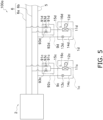
- the refrigeration cycle apparatus 100a can perform a simultaneous cooling and heating operation in which some of the plurality of utilization units 1 perform the heating operation and the remaining utilization units 1 perform the cooling operation.
- the refrigeration cycle apparatus 100a includes a high-pressure gas-refrigerant connection pipe 6a and a low-pressure gas-refrigerant connection pipe 6b as the gas-refrigerant connection pipes 6.
- the refrigeration cycle apparatus 100a includes a plurality of first shutoff valve units 9 instead of the plurality of first shutoff valve units 3 and the plurality of second shutoff valve units 4.
- the first shutoff valve unit 9 includes two first dividing pipes 91 and two first shutoff valves 93.
- One of the first dividing pipes 91 connects the high-pressure gas-refrigerant connection pipe 6a and the gas side of the utilization heat exchanger 11 of the utilization unit 1.
- the other one of the first dividing pipes 91 connects the low-pressure gas-refrigerant connection pipe 6b and the gas side of the utilization heat exchanger 11 of the utilization unit 1.
- the first shutoff valve unit 9 of the refrigeration cycle apparatus 100a includes two first dividing pipes 91 which are pipes through which the refrigerant flowing between the utilization unit 1 and each of the high-pressure gas-refrigerant connection pipe 6a and the low-pressure gas-refrigerant connection pipe 6b flows in parallel.
- the first shutoff valve 93 is provided in the first dividing pipe 91.
- a pipe 92d connects the liquid-refrigerant connection pipe 5 and the liquid side of the utilization heat exchanger 11 of the utilization unit 1.
- FIG. 5 illustrates an example in which the refrigeration cycle apparatus 100a includes two utilization units 1.
- subscripts c and d are added to the utilization units 1 and devices included in the utilization units 1.
- the number of the utilization units 1 is not limited to two, and may be three or more.
- the control unit 7 closes the utilization unit 1 in which the leakage of the refrigerant has been detected, and all the first shutoff valves 93 that shut off the refrigerant flowing between the utilization unit 1 and each of the high-pressure gas-refrigerant connection pipe 6a and the low-pressure gas-refrigerant connection pipe 6b.
- a second shutoff valve unit 4 may be further provided in the pipe 92d that connects the liquid-refrigerant connection pipe 5 and the utilization unit 1.
- Patent Literature 1 JP 2020-030043 A
Landscapes
- Engineering & Computer Science (AREA)
- Mechanical Engineering (AREA)
- General Engineering & Computer Science (AREA)
- Physics & Mathematics (AREA)
- Thermal Sciences (AREA)
- Chemical & Material Sciences (AREA)
- Combustion & Propulsion (AREA)
- Air Conditioning Control Device (AREA)
Applications Claiming Priority (2)
| Application Number | Priority Date | Filing Date | Title |
|---|---|---|---|
| JP2023170457A JP7648933B1 (ja) | 2023-09-29 | 2023-09-29 | 冷凍サイクル装置 |
| PCT/JP2024/026060 WO2025069668A1 (fr) | 2023-09-29 | 2024-07-22 | Dispositif à cycle frigorifique |
Publications (2)
| Publication Number | Publication Date |
|---|---|
| EP4553417A1 true EP4553417A1 (fr) | 2025-05-14 |
| EP4553417A4 EP4553417A4 (fr) | 2025-06-25 |
Family
ID=94341350
Family Applications (1)
| Application Number | Title | Priority Date | Filing Date |
|---|---|---|---|
| EP24804718.5A Pending EP4553417A4 (fr) | 2023-09-29 | 2024-07-22 | Dispositif à cycle frigorifique |
Country Status (4)
| Country | Link |
|---|---|
| EP (1) | EP4553417A4 (fr) |
| JP (1) | JP7648933B1 (fr) |
| CN (1) | CN121925532A (fr) |
| WO (1) | WO2025069668A1 (fr) |
Family Cites Families (10)
| Publication number | Priority date | Publication date | Assignee | Title |
|---|---|---|---|---|
| JP2877412B2 (ja) * | 1990-01-22 | 1999-03-31 | 三洋電機株式会社 | 空気調和装置 |
| AU2005264480B2 (en) * | 2004-07-16 | 2008-06-26 | Daikin Industries, Ltd. | Air conditioner |
| JP2006207959A (ja) * | 2005-01-31 | 2006-08-10 | Mitsubishi Electric Corp | 冷凍空調装置 |
| JP6126447B2 (ja) * | 2013-04-24 | 2017-05-10 | 東芝キヤリア株式会社 | 空気調和機 |
| JP6944987B2 (ja) * | 2015-06-26 | 2021-10-06 | ダイキン工業株式会社 | 空気調和システム |
| JP7152648B2 (ja) * | 2016-10-28 | 2022-10-13 | ダイキン工業株式会社 | 空気調和装置 |
| CN110199162B (zh) * | 2017-01-19 | 2021-09-14 | 三菱电机株式会社 | 冷冻循环装置 |
| JP6785974B2 (ja) * | 2017-08-18 | 2020-11-18 | 三菱電機株式会社 | 空気調和装置 |
| US11353234B2 (en) * | 2017-10-13 | 2022-06-07 | Mitsubishi Electric Corporation | Air conditioning system |
| US11131471B1 (en) * | 2020-06-08 | 2021-09-28 | Emerson Climate Technologies, Inc. | Refrigeration leak detection |
-
2023
- 2023-09-29 JP JP2023170457A patent/JP7648933B1/ja active Active
-
2024
- 2024-07-22 EP EP24804718.5A patent/EP4553417A4/fr active Pending
- 2024-07-22 WO PCT/JP2024/026060 patent/WO2025069668A1/fr active Pending
- 2024-07-22 CN CN202480062027.5A patent/CN121925532A/zh active Pending
Also Published As
| Publication number | Publication date |
|---|---|
| WO2025069668A1 (fr) | 2025-04-03 |
| JP7648933B1 (ja) | 2025-03-19 |
| CN121925532A (zh) | 2026-04-24 |
| JP2025059998A (ja) | 2025-04-10 |
| EP4553417A4 (fr) | 2025-06-25 |
Similar Documents
| Publication | Publication Date | Title |
|---|---|---|
| US10928092B2 (en) | Usage-side air-conditioning apparatus and air-conditioning apparatus provided with same | |
| US9958175B2 (en) | Air-conditioning apparatus | |
| CN102362126B (zh) | 空调装置 | |
| CN101231016B (zh) | 多联式空调机的管道连接检查装置及其方法 | |
| US11536502B2 (en) | Refrigerant cycle apparatus | |
| US11002467B2 (en) | Refrigeration cycle apparatus | |
| US20220290885A1 (en) | Air conditioning system | |
| US10794611B2 (en) | Refrigeration cycle apparatus | |
| CN109952479A (zh) | 空调装置以及空调系统 | |
| JPWO2019038797A1 (ja) | 空気調和装置および膨張弁ユニット | |
| KR100631539B1 (ko) | 멀티형 공기조화기의 통신선 오결선 검출시스템 및 방법 | |
| EP4113038A1 (fr) | Conditionneur d'air, procédé de commande et programme | |
| EP4553417A1 (fr) | Dispositif à cycle frigorifique | |
| JP7168022B2 (ja) | 空気調和機 | |
| CN115342492A (zh) | 用于控制多联机空调器的方法及装置、多联机空调器 | |
| CN1900678B (zh) | 空调检查方法 | |
| JP2022179215A (ja) | 冷媒漏洩管理システム | |
| CN114450543B (zh) | 空调机 | |
| US12085321B2 (en) | Refrigeration cycle system and refrigerant recovery apparatus | |
| EP4553418A1 (fr) | Dispositif à cycle frigorifique | |
| EP4553423A1 (fr) | Dispositif à cycle frigorifique | |
| EP4343236A1 (fr) | Dispositif à cycle frigorifique et système de détermination de fuite de réfrigérant | |
| EP4130912A1 (fr) | Système de diagnostic | |
| KR20250087147A (ko) | 공기 조화기 및 그 제어 방법 | |
| JP4948465B2 (ja) | 空気調和装置 |
Legal Events
| Date | Code | Title | Description |
|---|---|---|---|
| STAA | Information on the status of an ep patent application or granted ep patent |
Free format text: STATUS: UNKNOWN |
|
| STAA | Information on the status of an ep patent application or granted ep patent |
Free format text: STATUS: THE INTERNATIONAL PUBLICATION HAS BEEN MADE |
|
| PUAI | Public reference made under article 153(3) epc to a published international application that has entered the european phase |
Free format text: ORIGINAL CODE: 0009012 |
|
| STAA | Information on the status of an ep patent application or granted ep patent |
Free format text: STATUS: REQUEST FOR EXAMINATION WAS MADE |
|
| 17P | Request for examination filed |
Effective date: 20241119 |
|
| AK | Designated contracting states |
Kind code of ref document: A1 Designated state(s): AL AT BE BG CH CY CZ DE DK EE ES FI FR GB GR HR HU IE IS IT LI LT LU LV MC ME MK MT NL NO PL PT RO RS SE SI SK SM TR |
|
| A4 | Supplementary search report drawn up and despatched |
Effective date: 20250528 |
|
| RIC1 | Information provided on ipc code assigned before grant |
Ipc: F25B 49/00 20060101ALI20250522BHEP Ipc: F25B 13/00 20060101ALI20250522BHEP Ipc: F25B 49/02 20060101ALI20250522BHEP Ipc: F24F 11/36 20180101ALI20250522BHEP Ipc: F25B 41/20 20210101AFI20250522BHEP |
|
| P01 | Opt-out of the competence of the unified patent court (upc) registered |
Free format text: CASE NUMBER: UPC_APP_3793_4553417/2025 Effective date: 20250820 |