EP4553541A2 - Verfahren zur kombination von zwei oder mehr sätzen von korrekturen mit präziser punktpositionierung (ppp) mit ausrichtung ionosphärischer korrekturen - Google Patents
Verfahren zur kombination von zwei oder mehr sätzen von korrekturen mit präziser punktpositionierung (ppp) mit ausrichtung ionosphärischer korrekturen Download PDFInfo
- Publication number
- EP4553541A2 EP4553541A2 EP24184251.7A EP24184251A EP4553541A2 EP 4553541 A2 EP4553541 A2 EP 4553541A2 EP 24184251 A EP24184251 A EP 24184251A EP 4553541 A2 EP4553541 A2 EP 4553541A2
- Authority
- EP
- European Patent Office
- Prior art keywords
- navigation
- corrections
- correction
- correction system
- transformed
- Prior art date
- Legal status (The legal status is an assumption and is not a legal conclusion. Google has not performed a legal analysis and makes no representation as to the accuracy of the status listed.)
- Pending
Links
Images


Classifications
-
- G—PHYSICS
- G01—MEASURING; TESTING
- G01S—RADIO DIRECTION-FINDING; RADIO NAVIGATION; DETERMINING DISTANCE OR VELOCITY BY USE OF RADIO WAVES; LOCATING OR PRESENCE-DETECTING BY USE OF THE REFLECTION OR RERADIATION OF RADIO WAVES; ANALOGOUS ARRANGEMENTS USING OTHER WAVES
- G01S19/00—Satellite radio beacon positioning systems; Determining position, velocity or attitude using signals transmitted by such systems
- G01S19/01—Satellite radio beacon positioning systems transmitting time-stamped messages, e.g. GPS [Global Positioning System], GLONASS [Global Orbiting Navigation Satellite System] or GALILEO
- G01S19/03—Cooperating elements; Interaction or communication between different cooperating elements or between cooperating elements and receivers
- G01S19/07—Cooperating elements; Interaction or communication between different cooperating elements or between cooperating elements and receivers providing data for correcting measured positioning data, e.g. DGPS [differential GPS] or ionosphere corrections
- G01S19/072—Ionosphere corrections
-
- G—PHYSICS
- G01—MEASURING; TESTING
- G01S—RADIO DIRECTION-FINDING; RADIO NAVIGATION; DETERMINING DISTANCE OR VELOCITY BY USE OF RADIO WAVES; LOCATING OR PRESENCE-DETECTING BY USE OF THE REFLECTION OR RERADIATION OF RADIO WAVES; ANALOGOUS ARRANGEMENTS USING OTHER WAVES
- G01S19/00—Satellite radio beacon positioning systems; Determining position, velocity or attitude using signals transmitted by such systems
- G01S19/01—Satellite radio beacon positioning systems transmitting time-stamped messages, e.g. GPS [Global Positioning System], GLONASS [Global Orbiting Navigation Satellite System] or GALILEO
- G01S19/03—Cooperating elements; Interaction or communication between different cooperating elements or between cooperating elements and receivers
- G01S19/04—Cooperating elements; Interaction or communication between different cooperating elements or between cooperating elements and receivers providing carrier phase data
-
- G—PHYSICS
- G01—MEASURING; TESTING
- G01S—RADIO DIRECTION-FINDING; RADIO NAVIGATION; DETERMINING DISTANCE OR VELOCITY BY USE OF RADIO WAVES; LOCATING OR PRESENCE-DETECTING BY USE OF THE REFLECTION OR RERADIATION OF RADIO WAVES; ANALOGOUS ARRANGEMENTS USING OTHER WAVES
- G01S19/00—Satellite radio beacon positioning systems; Determining position, velocity or attitude using signals transmitted by such systems
- G01S19/01—Satellite radio beacon positioning systems transmitting time-stamped messages, e.g. GPS [Global Positioning System], GLONASS [Global Orbiting Navigation Satellite System] or GALILEO
- G01S19/03—Cooperating elements; Interaction or communication between different cooperating elements or between cooperating elements and receivers
- G01S19/07—Cooperating elements; Interaction or communication between different cooperating elements or between cooperating elements and receivers providing data for correcting measured positioning data, e.g. DGPS [differential GPS] or ionosphere corrections
- G01S19/073—Cooperating elements; Interaction or communication between different cooperating elements or between cooperating elements and receivers providing data for correcting measured positioning data, e.g. DGPS [differential GPS] or ionosphere corrections involving a network of fixed stations
Definitions
- the invention relates generally to navigation corrections, and in particular, to systems, methods, and media for transforming navigation corrections into transformed corrections that are compatible with other independently generated navigation corrections.
- PPP Precise point positioning
- Classic PPP (without ambiguity resolution) may be able to achieve a positional accuracy of 10 cm after a convergence time of several tens of minutes, for example.
- Techniques enabling PPP with ambiguity resolution (PPP-AR) have been introduced to achieve the same or better position accuracy with considerably reduced convergence time.
- PPP-AR methods typically use determined correction data in order to resolve carrier phase ambiguities.
- a server may process observations from a global network of reference stations to estimate code and phase biases in addition to satellite clock corrections (collectively referred to as global corrections).
- the corrections determined at the server depend on some parameters that are set to arbitrary values.
- the global corrections may then be broadcast, and a receiver can use a single set of the global corrections to resolve the carrier phase ambiguities such that high positioning accuracy can be achieved with a convergence time that is considerably reduced when compared to classic PPP.
- a global ionospheric correction is not included in the global corrections. This is because the generation of global ionospheric corrections, i.e., a global ionospheric model, is impractical. Specifically, the generation of a global ionospheric model would require a very dense network of reference stations that provide ionospheric data to the server. To accurately model the ionospheric effect, the server would have to simultaneously process the ionospheric data from a plurality of reference stations. This is impractical because it would require vast processing capabilities and a dedicated channel between the server and each of a plurality of different reference stations.
- regional ionospheric models do exist for some geographical areas.
- traditional PPP-AR methods can alternatively use regional corrections to, almost instantaneously, resolve carrier phase ambiguities such that high position accuracy is achieved.
- regional corrections may include estimated code and phase biases, estimated satellite clock corrections, and estimated ionospheric corrections.
- the local corrections depend on parameters that are set to arbitrary values. These arbitrary values of the parameters may be, and are likely to be, different than the arbitrary values of the parameters used to estimate the global corrections. In fact, the arbitrary values of the parameters may be different even for different sets of corrections for the same (e.g., overlapping) area.
- the independently generated corrections e.g., global corrections and regional corrections
- the ionospheric corrections that are specific to a geographical area cannot simply be utilized with the global corrections to achieve high position accuracy with reduced convergence time.
- the estimation of the global corrections is directly dependent on the arbitrary values that are selected/used for the global parameters.
- the estimation of the local corrections is directly dependent on the arbitrary values that are selected/used for the local parameters of the geographical area. Because the values of the global and local parameters are different, the global corrections and local corrections, which are generated independently, are incompatible and cannot be used interchangeably according to traditional approaches.
- the receiver can implement a traditional PPP-AR method using (1) the global corrections that do not include ionospheric corrections or (2) local corrections for a geographical area when the receiver is located in the geographical area.
- Techniques are provided for transforming navigation corrections into transformed navigation corrections that are compatible with other independently generated corrections according to the one or more embodiments as described herein. Because the transformed navigation corrections are compatible with the other independently generated corrections, the two sets of corrections can be used together to implement a positioning technique (e.g., PPP-AR).
- a positioning technique e.g., PPP-AR
- a navigation correction system may generate one or more navigation corrections.
- the navigation correction system may execute a correction algorithm that sets one or more parameters to arbitrary values to generate the one or more navigation corrections. Additionally, the navigation correction system may receive other navigation corrections, e.g., reference navigation corrections, which are independently generated by a different navigation correction system.
- the different navigation correction system may execute a correction algorithm that sets one or more parameters to arbitrary values to generate the reference navigation corrections.
- the arbitrary values of the parameters may be, and are likely to be, different across different navigation correction systems.
- a processor of the navigation correction system may execute a module (e.g., a correction transformation module) that transforms one or more of its generated corrections.
- the module may use the reference corrections with the generated corrections to calculate estimated delta values from a single difference (between satellites) system of one or more equations.
- the system of one or more equations may be for code and phase observations, or for any other types of observations.
- the module may adjust a selected generated correction by a corresponding calculated estimated delta value to generate a transformed navigation correction.
- the transformed navigation correction is compatible with the reference corrections. As such, the transformed navigation correction can be used with the reference corrections. Transformed corrections may be transmitted (e.g., broadcast) over one or more networks to a navigation receiver.
- the navigation receiver may use the transformed corrections with the reference corrections to implement a positioning technique.
- the navigation receiver may use the transformed corrections with the reference corrections when implementing PPP-AR.
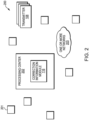
- Fig. 1 is an illustration of an example system environment 100 for transforming navigation corrections into transformed navigation corrections that are compatible with other independently generated navigation corrections according to the one or more embodiments as described herein.
- System environment 100 includes a body of interest 102, e.g., a moving vehicle, a stationary object, etc. Coupled to the body of interest 102 may be a receiver 104 and an antenna 106.
- the antenna 106 coupled to the body of interest 102 and in communication with receiver 104, may receive one or more signals from one or more transmitters 108.
- the one or more transmitters 108 may be one or more Global Navigation Satellite System (GNSS) satellites that transmit one or more navigation signals, e.g., GNSS satellite signals (not shown).
- GNSS Global Navigation Satellite System
- transmitters 108 may be terrestrial transmitters that transmit any of a variety of different navigation signals.
- the description of transmitters 108 being GNSS satellites that transmit GNSS signals are for illustrative purposes only.
- system environment 100 includes a plurality of different navigation correction systems 112, where each individual navigation correction system may be referred to as a navigation correction system 200.
- navigation correction system and correction system may be used interchangeably.
- the ellipsis in Fig. 1 is used to indicate that the plurality of correction systems 112 includes any number, but at least two, different individual navigation correction systems 200.
- Each correction system 200 may generate navigation correction data.
- navigation corrections and corrections may be used interchangeably.
- Each correction system 200 may include processors, memory, storage, other hardware, software, and/or firmware (not shown).
- each correction system 200 executes a correction algorithm that generates its corresponding corrections by setting some parameters to arbitrary values.
- the arbitrary values of the parameters may be, and are likely to be, different across different individual correction systems 200.
- Each correction system 200 of the plurality of correction systems 112 may provide, over one or more networks 114, corrections to a different correction system 200 and/or receiver 104.
- the one or more networks 114 may be any wired or wireless network.
- the one or more networks 114 may include, but are not limited to, an Internet Protocol (IP) based delivery system (wired or wireless), a mobile network such as Long-Term Evolution (LTE), or the 5 th generation (5G) mobile network, a satellite-based delivery system such as Inmarsat, etc.
- IP Internet Protocol
- LTE Long-Term Evolution
- 5G 5 th generation
- satellite-based delivery system such as Inmarsat, etc.
- Receiver 104 may, based on the reception of signals at antenna 106, produce raw measurements (e.g., GNSS raw measurements), such as pseudoranges, carrier phases, and Doppler velocities; position (e.g., GNSS position), velocity (e.g., GNSS velocity), attitude, and time (e.g., GNSS time), position covariance, time covariance, and velocity covariance; and, as appropriate, GNSS observables ("GNSS data").
- Receiver 104 may include processors, memory, storage, other hardware, software, and/or firmware (not shown).
- the receiver 104 may also utilize the GNSS data with the received corrections to mitigate errors (e.g., orbit, clock, antenna, and/or atmospheric induced errors), resulting in the calculation of decimeter-level or better positioning accuracy with reduced convergence time.
- receiver 104 may utilize the GNSS data with the received corrections to implement precise point positioning with ambiguity resolution (PPP-AR) to achieve a positional accuracy of 10 cm or better with reduced convergence.
- PPP-AR precise point positioning with ambiguity resolution
- receiver 104 may utilize the GNSS data with corrections received from different correction systems (which provide reference corrections and/or transformed corrections) to implement PPP-AR to avoid reoccurring convergence periods.
- receiver 104 may receive corrections (e.g., reference corrections) from a first correction system 200.
- Receiver 104 may also receive one or more transformed corrections, which are transformed to be consistent/compatible with the reference corrections, from a second correction system 200.
- Receiver 104 may implement PPP-AR using the reference corrections, transformed corrections, and GNSS data to calculate decimeter-level or better positioning accuracy with shorter convergence time while also avoiding reoccurring convergence periods.
- first and second is not meant to indicate a temporal relationship between two different correction systems 200. Instead, “first” and “second” are illustratively used to differentiate between different individual correction systems 200 that are referenced in the accompanied examples.
- Fig. 2 is an illustration of an example navigation correction system according to the one or more embodiments as described herein.
- the example navigation correction system 200 may include a plurality of reference stations (e.g., base stations) 201 that define a network.
- Each of the reference stations 201 may be installed at a precisely known location and receive signals from transmitters 108.
- the number and locations of the reference stations 201 in Fig. 2 is for illustrative purposes only. For simplicity and ease of understanding, only one reference station 201 in Fig. 2 includes reference number 201, but it is expressly contemplated that each of reference stations in Fig. 2 are associated with reference number 201.
- the navigation correction system 200 may also include a processing center 202.
- the location of the processing center 202 in relation to reference stations 201 is for illustrative purposes only.
- the processing center 202 is a computing device (e.g., server) with a processor (not shown) and a memory (not shown).
- the processing center 202 can generate corrections based on the signals received from the plurality of reference stations 201.
- the processing center 202 may receive the signals from the plurality of reference stations 201 over one or more networks 203.
- the one or more networks 203 may be the same as networks 114 of Fig. 1 or different networks.
- the one or more networks 203 may be any wired or wireless network.
- the one or more networks 203 may include, but are not limited to, an IP based delivery system (wired or wireless), a mobile network such as LTE, or the 5G mobile network, a satellite-based delivery system such as Inmarsat, etc.
- the processing center 202 may execute a correction algorithm that sets some parameters to arbitrary values to generate corresponding corrections from the data of the reference station signals.
- a first correction system 200 may be a global correction system with a plurality of reference stations 201 that are distributed globally to define a global network.
- the processing center 202 generates global corrections (e.g., satellite clock, code, and phase corrections) based on the signals received from the globally distributed reference stations 201.
- the processing center 202 corresponding to the global correction system 200 may execute a correction algorithm, which sets some parameters to arbitrary values, to generate the global corrections from the data from the reference station signals.
- Such global corrections are valid globally and can be used by receiver 104 regardless of the location of receiver 104.
- a second correction system 200 may be a regional correction system with a plurality of reference stations 201 that are distributed in a region to define a regional network.
- the processing center 202 generates regional corrections (e.g., satellite clock, code, phase, and ionospheric corrections) based on the signals received from the regionally distributed reference stations 201.
- the processing center 202 corresponding to the regional correction system 200 may execute a correction algorithm, which sets some parameters to arbitrary values, to generate the regional corrections from the data from the reference station signals.
- the global corrections and regional corrections are generated independently and using correction algorithms that set parameter values arbitrarily, the global corrections and regional corrections as independently generated cannot simply be used together.
- sets of different regional corrections are generated independently and using correction algorithms that set parameter values arbitrarily, the sets of different regional corrections as independently generated cannot simply be used together.
- the same correction algorithm cannot simply be used across different correction systems (e.g., correction networks) because the arbitrary parameters can be, and are likely, different across different correction systems.
- each correction system 200 includes a correction transformation module 116 that can transform one or more corrections to generate transformed corrections that can be used with reference corrections that are independently generated by a different correction system 200.
- the correction transformation module 116 of one or more regional correction systems 200 may transform one or more regional corrections, e.g., ionospheric corrections, to generate transformed regional corrections.
- the transformed regional corrections can be used with global reference corrections (e.g., satellite clock, code, and phase corrections) that are independently generated by a global correction system 200.
- corrections may be independently generated in parallel by a plurality of different correction systems 200, and corrections generated by any number of correction systems 200 can be transformed such that they are compatible with and can be used with a set of other corrections (i.e., reference corrections) that are generated by a different correction system 200.
- correction systems 200 that are global and regional, it is expressly contemplated that the one or more embodiments as described herein are applicable to any of a variety of different correction systems 200 that independently generate corrections based on an execution of a specific algorithm that sets parameter values arbitrarily. As such, the description of global and regional correction systems 200 is for illustrative purposes only.
- the reference stations 201 of a correction system 200 may be divided into a plurality of sub-networks, and the data from each sub-network of reference stations 201 may be processed independently and in parallel by the processing center 202 to generate sub-network corrections.
- One of the sub-network corrections may be reference corrections and the other sub-network corrections (e.g., integer ambiguity corrections) may be transformed to generate a single valid set of corrections for the divided correction system 200 according to the one or more embodiments as described herein.
- corrections may be independently generated in parallel by a plurality of sub-networks of a correction system 200, and corrections generated by all but one of the sub-networks can be transformed such that they are compatible with reference corrections that are generated by the other remaining sub-networks. As a result, a valid set of corrections can be generated across the correction system 200 that is divided into sub-networks.
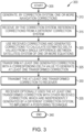
- Fig. 3 is a flow diagram of a sequence of steps for transforming navigation corrections into transformed corrections that are compatible with other independently generated navigation corrections according to the one or more embodiments as described herein.
- Procedure 300 starts at step 305 and continues to step 310.
- a correction system 200 generates one or more navigation corrections.
- processing center 202 of a particular correction system 200 generates corrections based on the signals received from the plurality of reference stations 201.
- the processing center 202 of correction system 200 executes a correction algorithm, which sets some parameters to arbitrary values, to generate corresponding corrections based on the data from the reference stations signals.
- the correction system 200 in step 310 is a regional correction system.
- the regional correction system 200 includes a plurality of reference stations 201 that are distributed in a region to define a regional network.
- the processing center 202 corresponding to the regional correction system 200 may execute a correction algorithm, which sets some parameters to arbitrary values, to generate the regional corrections from the data from the regional reference station signals.
- such regional corrections may include, but are not limited to, a satellite clock correction ( g ⁇ s ), a code correction ( b F s g ) , phase correction ( l F s g ) , ionospheric slant delay ( I r s g ) , tropospheric slant delay ( T r s g ), and integer ambiguity ( n Fr s g ) ; wherein the index g denotes generated, e.g., corrections generated by a first correction system that in this example is the regional correction system 200.
- the correction system 200 receives reference corrections from a different correction system 200.
- the first correction system 200 which generates the regional corrections in step 310, may receive the reference corrections from a different correction system 200 (e.g., second correction system 200) over network 114.
- the second correction system 200 is a global correction system.
- the global correction system 200 includes a plurality of reference stations 201 that are distributed globally to define a global network.
- the processing center 202 corresponding to the global correction system 200 may execute a correction algorithm, which sets some parameters to arbitrary values, to generate the global corrections from the data from the global reference station signals.
- such global corrections may include, but are not limited to, a satellite clock correction ( R ⁇ s ), a code correction ( b F s R ) , and a phase correction ( l F s R ); wherein the index R denotes reference, e.g., reference corrections received from a second different correction system that generates the reference corrections and in this example is the global correction system 200.
- the generated corrections e.g., regional corrections
- the received reference corrections e.g., global corrections
- the first and second correction systems 200 set the parameter values arbitrarily when independently generating their respective corrections, the independently generated corrections cannot simply be used with each other.
- the one or more embodiments as described herein overcome this deficiency as described in further detail below.
- the procedure 300 continues to step 320 and the correction transformation module 116 of the correction system 200 uses the received reference corrections and the generated corrections to calculate estimated delta values from a single difference (between satellites) system of one or more equations.
- the system of one or more equations may be for code and phase observations.
- the system of one or more equations may be for any of a variety of different types of observations. For the example described in relation to Fig. 2 , let it be assumed that the system of one or more equations are for code and phase observations.
- equations (3a) and (3b) do not depend on the receiver, e.g., none of the variables on the left side of equations (3a) and (3b) have a subscript of r. Further, the right side of equations (3a) and (3b) only included estimated delta (" ⁇ ") values and constants such as frequency and wavelength, which are independent of the receiver. Therefore, the receiver index of r can be omitted from equations (3a) and (3b).
- ⁇ g T s T r s g ⁇ T r s R
- equations (4a) and (4b) together form the system of one or more equations for code and phase observations that are solved to calculate estimated delta values of: g ⁇ T s , g ⁇ I s , ⁇ g n F s , g ⁇ , g ⁇ b F , g ⁇ l F .
- step 325 the correction transformation module 116 transforms at least one generated correction with a corresponding estimated delta value to generate at least one transformed correction.
- the correction transformation module 116 may calculate other transformed corrections in a similar manner and using the other estimated delta values (e.g., g ⁇ T s g ⁇ , g ⁇ b F , g ⁇ l F ) .
- the transformed correction is compatible with the received reference corrections.
- the transformed ionospheric correction ( I r s R ) that is generated in step 325 is compatible with the received global reference corrections.
- compatible means that a transformed correction can be used with different corrections that are independently generated by a different correction system that sets parameters to arbitrary values when generating the different corrections.
- the one or more embodiments as described herein provide an improvement in the existing technological field of navigation systems. Stated another way, because the one or more embodiments as described herein generate transformed corrections that are compatible with reference corrections, a network of different yet compatible corrections can be broadcast to receivers that can use the different but compatible corrections. As such, the generation of the transformed corrections amounts to a significantly more robust network of correction systems that are compatible with each other.
- the correction system 200 transmits the at least one transformed correction to receiver 104.
- the correction system 200 may transmit (i.e., broadcast) the at least one transformed corrections over network 114 to receiver 104.
- the regional correction system 200 may transmit the transformed ionosphere slant delay to receiver 104.
- the one or more embodiments as described herein provide an improvement in the technological field of navigation systems. That is, the one or more embodiments as described herein allow a network of a plurality of different correction systems 200, that each generate corrections independently and based on arbitrarily set parameter values, to transmit compatible corrections to navigation receivers. By transmitting compatible corrections to navigation receivers, the one or more embodiments as described herein provide an improvement in the existing technological field of navigation systems.
- receiver 104 uses the at least one transformed correction with other received corrections (e.g., reference corrections), which are independently generated by a different correction system, to implement a positioning technique.
- the positioning technique is PPP-AR that allows receiver 104 to achieve a positional accuracy of 10 cm or better with reduced convergence time when, for example, compared to classic PPP.
- the receiver 104 may resolve carrier phase ambiguities at each epoch using GNSS data, the reference corrections, and the transformed corrections.
- the procedure 300 ends at step 340.
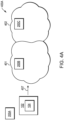
- Figs. 4A-4C are illustrations of an example body of interest 102 (e.g., vehicle) with a coupled receiver 104 that uses transformed corrections with independently generated other corrections (e.g., reference corrections) as the body of interest 102 moves according to the one or more embodiments as described herein.
- body of interest 102 e.g., vehicle
- a coupled receiver 104 that uses transformed corrections with independently generated other corrections (e.g., reference corrections) as the body of interest 102 moves according to the one or more embodiments as described herein.
- correction system 200A is a global correction system
- correction systems 200B and 200C are two different regional correction systems.
- Regional correction systems 200B and 200C may correspond to the regions that are defined by perimeters 401 and 402, respectively.
- the regions defined by perimeters 401 and 402 may share a boundary.
- regions that are covered by corrections systems do not need to share a boundary and in fact may be completely distinct, overlap, share one or more boundaries, etc. according to the one or more embodiments as described herein.
- each of the correction systems 200A-200C do in fact include base stations 201, a processing center 202, and a correction transformation module 116 that operate as described above in relation to Figs. 2 and 3 .
- Each of correction systems 200A-200C independently generate their respective corrections by setting some parameters to arbitrary values.
- the corrections that are independently generated cannot simply be mixed or used with corrections that are independently generated by a different correction system.
- the global corrections that are generated by global correction system 200A cannot simply be used with the regional corrections that are respectively generated by regional correction systems 200B and 200C. Therefore, and as described above in relation to the flow diagram of Fig. 3 , the correction transformation module 116 of a correction system (e.g., 200A-200C) may transform one or more generated corrections to generate one or more transformed corrections that can be used with other independently generated corrections.
- each of regional correction systems 200B and 200C may transform their respectively generated regional correction such that the transformed corrections can be used with the global corrections that are independently generated by global correction system 200A.
- environment 400A includes body of interest 102 with receiver 104 that is not located in a geographical location that is covered by a regional correction system. Specifically, the location of the body of interest 102 with receiver 104 is not within the geographical areas that are defined by perimeters 401 and 402 that correspond to regional correction systems 200B and 200C, respectively. Because the receiver 104 is not located in the geographical areas that are defined by perimeters 401 and 402 as depicted in Fig. 4A , receiver 104 cannot use the regional corrections that are independently generated by corrections systems 200B and 200C.
- receiver 104 may receive global corrections from global correction system 200A over network 114.
- the receiver 104 may utilize the global corrections with GNSS data to implement a positioning technique.
- the positioning technique may be PPP-AR.
- the global corrections do not include an ionospheric correction (e.g., slant delay value)
- the ionospheric correction is an unknown parameter that is estimated during PPP-AR.
- the receiver 104 may resolve carrier phase ambiguities at each epoch using the GNSS data with the global corrections when, for example, the body of interest 102 is not within the geographical areas corresponding to the correction systems 200B and 200C.
- arrow 407 indicates that the body of interest 102 is moving toward the geographical area that is defined by perimeter 401 and that corresponds to correction system 200B.
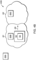
- Fig. 4B is environment 400B and represents a point in time when body of interest 102 is within the geographical area that is defined by perimeter 401 and that corresponds to correction system 200B.
- receiver 104 could either (1) continue to use the global corrections to implement PPP-AR or (2) switch over and use the regional corrections that are generated by correction system 200B.
- continuing to use the global corrections is not desirable because reduced and optimal convergence time is not achieved since some parameters (e.g., ionospheric correction) are unknown parameters and have to be estimated. Therefore, with conventional systems and techniques, receiver 104 could switch over and use the regional corrections that are generated by correction system 200B.
- receiver 104 would have to reset its filter (e.g., position filter) which causes reoccurrence of the convergence period, which is undesirable.
- filter e.g., position filter
- Conventional systems and techniques cannot, for example, use a regional correction, e.g., the ionospheric correction, with the independently generated global corrections because the regional and global corrections are generated independently based on some parameters being set to arbitrary values.
- the regional corrections can be transformed to be compatible with the global corrections as described above with relation to the flow diagram of Fig. 3 .
- the regional correction system 200B may receive the independently generated global corrections from global correction system 200A over network 114.
- the regional correction system 200B may use the independently generated global corrections with its generated regional corrections to transform the regional corrections, e.g., ionospheric correction, into a transformed correction that is compatible with the global corrections.
- the receiver 104 can use the transformed corrections, e.g., transformed ionospheric correction, generated by correction system 200B.
- the receiver 104 can, without resetting the filter, use the GNSS data with the transformed regional correction and the received global corrections to implement PPP-AR while in the geographical area defined by perimeter 401. Because the filter does not have to be reset, the reoccurrence of the convergence period is avoided according to the one or more embodiments as described herein.
- receiver 104 While receiver 104 is in the geographical area defined by perimeter 401, receiver 104 can, without resetting the filter, continue to use the GNSS data with global corrections received from correction system 200A and the transformed corrections received from correction system 200B. Therefore, reoccurrence of the convergence period is avoided when implementing PPP-AR using the transformed corrections with the independently generated global corrections according to the one or more embodiments as described herein.
- arrow 408 indicates that the body of interest 102 is moving towards the geographical area that is defined by perimeter 402 and that corresponds to correction system 200C.
- Fig. 4C is environment 400C and represents a point in time when body of interest 102 is within the geographical area that is defined by perimeter 402 and that corresponds to correction system 200C. Because receiver 104 is no longer in the geographical area defined by perimeter 401 that corresponds to correction system 200B, receiver 104 can no longer use the transformed corrections generated by correction system 200B. However, and as will be described in further detail below, receiver 104 can use the transformed corrections generated by correction system 200C to implement PPP-AR.
- receiver 104 When receiver 104 is in the geographical area that is defined by perimeter 402, conventional systems and techniques would require that receiver 104 (1) switch over and use the global corrections or (2) switch over and use the regional corrections that are generated by correction system 200C. As explained above, this is due to the incompatibility between corrections that are independently generated based on some parameters being set to arbitrary values. In both instances, and according to conventional systems and techniques, the receiver 104 would have to reset its filter to implement PPP-AR with the global corrections or the regional corrections from correction system 200C. As a result, reoccurrence of the convergence period is required.
- the regional corrections e.g., ionospheric correction
- the regional correction system 200C may receive the independently generated global corrections from global correction system 200A over network 114.
- the regional correction system 200C may use the independently generated global corrections with its generated regional corrections to transform the regional corrections, e.g., ionospheric correction, into a transformed correction that is compatible with the global corrections.
- the receiver 104 can use the transformed corrections, e.g., transformed ionospheric correction, generated by correction system 200C.
- the receiver 104 can, without resetting the filter, use the GNSS data with the transformed regional corrections and the global corrections to implement PPP-AR while in the geographical area defined by perimeter 402. Because the filter does not have to be reset, the reoccurrence of the convergence period is avoided according to the one or more embodiments as described herein.
- receiver 104 While receiver 104 is in the geographical area defined by perimeter 402, receiver 104 can, without resetting the filter and thus avoiding reoccurrence of the convergence period, continue to use the GNSS data with global corrections received from correction system 200A and the transformed corrections received from correction system 200C.
- the one or more embodiments as described herein allow the receiver 104 to implement PPP-AR by seamlessly mixing reference corrections (e.g., global corrections) with transformed corrections that correspond to the geographical area in which the receiver 104 is located without requiring receiver 104 to reset its filter.
- reference corrections e.g., global corrections
- each of the 10 regional correction systems may receive the global corrections over network 114.
- Each of the 10 regional correction systems may transform their respective regional corrections to be compatible with the global corrections in the manner described above in relation to Fig. 3 .
- receiver 104 may use the global corrections to implement PPP-AR when the receiver 104 is not located in the 10 geographical areas corresponding to the 10 regional correction systems.
- the receiver 104 can use the transformed corrections with the global corrections to implement PPP-AR.
- the receiver 104 does not have to reset its filter and can instead seamlessly mix the global corrections with the transformed corrections to implement PPP-AR as the receiver moves in and out of the 10 different geographical areas.
- This is in contrast to conventional systems and techniques that, for example, require the receiver 104 to reset its filter every time the receiver has to switch over and use different corrections as the receiver 104 moves into and out of the different geographical areas.
- the one or more embodiments as described herein avoid reoccurrence of the convergence period.
- any set of corrections that are generated by a correction system 200 may be the reference corrections.
- the regional corrections generated by a particular regional correction system can be the reference corrections and other corrections that are independently generated by other correction systems (e.g., global correction system, other regional correction systems) can be transformed to be compatible with the reference regional corrections.
- the examples as described herein relate to correction systems that generate corrections based on the propagation of GNSS signals that may, for example, be impacted by a variety of different factors (e.g., ionosphere, clock error, etc.).
- the one or more embodiments as described herein are applicable to correction systems that generate navigation corrections based on the propagation of any types of signals that may be impacted by any factors.
- a correction system may generate corrections based on the propagation of terrestrial signals that may be impacted by variations in the propagation medium, such as salinity, composition, pressure, water content, infrastructure, etc.
- the one or more embodiments as described herein are applicable to these types of corrections systems and any of a variety of other types of correction systems that generate corrections from signals that are impacted by varying factors. As such, the description of corrections that are generated based on the propagation of GNSS signals is for illustrative purposes only.
- a correction system for a large geographical area may be divided into a plurality of sub-networks.
- a regional correction system 200 is divided into 6 different sub-networks including different base stations 201.
- the processing center 202 of the regional correction system 200 may generate, in parallel, corrections for the 6 different sub-networks.
- the generated corrections for a single particular sub-network, e.g., first sub-network may be the reference corrections and the corrections for the 5 other sub-networks may be transformed to be compatible with the sub-network reference corrections in the manner described above in relation to Fig. 3 .
- a single valid set of compatible corrections exist for the correction system 200 that is divided into 6 sub-networks according to the one or more embodiments as described herein.
- the one or more embodiments as described herein conserve processing resources when compared to conventional systems that have to generate a single set of corrections based on all the base stations 201 for the large geographical area. Therefore, it should be expressly understood that the examples as described herein are for illustrative purposes only and any correction system or sub-network of a correction system may generate corrections that can be the reference corrections according to the one or more embodiments as described herein.
- combined software/hardware implementations may include both electronic device-executable instructions stored in a non-transitory electronic device-readable medium, as well as one or more hardware components.
- electronic device-executable instructions stored in a non-transitory electronic device-readable medium, as well as one or more hardware components.
Landscapes
- Engineering & Computer Science (AREA)
- Radar, Positioning & Navigation (AREA)
- Remote Sensing (AREA)
- Computer Networks & Wireless Communication (AREA)
- Physics & Mathematics (AREA)
- General Physics & Mathematics (AREA)
- Position Fixing By Use Of Radio Waves (AREA)
Applications Claiming Priority (1)
| Application Number | Priority Date | Filing Date | Title |
|---|---|---|---|
| US18/387,638 US20250147190A1 (en) | 2023-11-07 | 2023-11-07 | Method for combining two or more sets of precise point positioning (ppp) corrections including aligning ionospheric corrections |
Publications (2)
| Publication Number | Publication Date |
|---|---|
| EP4553541A2 true EP4553541A2 (de) | 2025-05-14 |
| EP4553541A3 EP4553541A3 (de) | 2025-05-28 |
Family
ID=91670450
Family Applications (1)
| Application Number | Title | Priority Date | Filing Date |
|---|---|---|---|
| EP24184251.7A Pending EP4553541A3 (de) | 2023-11-07 | 2024-06-25 | Verfahren zur kombination von zwei oder mehr sätzen von korrekturen mit präziser punktpositionierung (ppp) mit ausrichtung ionosphärischer korrekturen |
Country Status (3)
| Country | Link |
|---|---|
| US (1) | US20250147190A1 (de) |
| EP (1) | EP4553541A3 (de) |
| CA (1) | CA3248478A1 (de) |
Family Cites Families (6)
| Publication number | Priority date | Publication date | Assignee | Title |
|---|---|---|---|---|
| NL2013472B1 (en) * | 2014-09-15 | 2016-09-28 | Fugro N V | Integer Ambiguity-Fixed Precise Point Positioning method and system. |
| EP3035080B1 (de) * | 2014-12-16 | 2022-08-31 | Trimble Inc. | Satellitennavigationssystem mit Positionierung mit Erzeugung von Korrektur-Informationen |
| US10802160B2 (en) * | 2016-03-18 | 2020-10-13 | Deere & Company | Rapid determination of precise position by aiding data |
| US11378699B2 (en) * | 2020-07-13 | 2022-07-05 | Swift Navigation, Inc. | System and method for determining GNSS positioning corrections |
| US11852733B2 (en) * | 2021-03-10 | 2023-12-26 | Raytheon Company | Method for the generation of satellite clock and orbit corrections for global navigation satellite systems (GNSS) |
| US11846714B2 (en) * | 2021-08-11 | 2023-12-19 | Qualcomm Incorporated | Precise point positioning (PPP) with modified satellite and clock error mitigation |
-
2023
- 2023-11-07 US US18/387,638 patent/US20250147190A1/en active Pending
-
2024
- 2024-06-25 EP EP24184251.7A patent/EP4553541A3/de active Pending
- 2024-07-12 CA CA3248478A patent/CA3248478A1/en active Pending
Also Published As
| Publication number | Publication date |
|---|---|
| CA3248478A1 (en) | 2025-10-31 |
| US20250147190A1 (en) | 2025-05-08 |
| EP4553541A3 (de) | 2025-05-28 |
Similar Documents
| Publication | Publication Date | Title |
|---|---|---|
| US10185038B2 (en) | Integer ambiguity-fixed precise point positioning method and system | |
| RU2752827C1 (ru) | Способ и система дифференциальной коррекции навигации | |
| US8989652B2 (en) | Advanced timing and time transfer for satellite constellations using crosslink ranging and an accurate time source | |
| US10739471B2 (en) | GNSS receiver with a capability to resolve ambiguities using an uncombined formulation | |
| EP2715391B1 (de) | Charakterisierung lokaler Fehler für ein sekundäres Nicht-GPS Positionierungssignal mithilfe eines erweiterten Differentialkorrektursystems unter Verwendung beweglicher Referenzempfänger | |
| KR101360918B1 (ko) | 무선항법 신호 처리방법 | |
| CN107861131B (zh) | 一种斜路径电离层延迟的获取方法及系统 | |
| US11953607B2 (en) | Navigation with differential carrier phase measurement from low earth orbit satellites | |
| US8456354B2 (en) | System and method for applying augmentation corrections for GNSS positioning | |
| US20150247931A1 (en) | Locally enhanced gnss wide-area augmentation system | |
| US20230358898A1 (en) | Precise point positioning methods, devices and systems | |
| Komodromos et al. | Network-aided pseudorange-based LEO PNT from OneWeb | |
| EP2995973B1 (de) | Verfahren und system zur genauen relativen dynamic-to-dynamic-positionierung unter verwendung globaler satellitennavigationssysteme | |
| EP3861375B1 (de) | Verfahren zur bereitstellung von korrekturinformationen, mehrere referenzstationen und zentrale recheneinheit, gns-system und software-produkt und/oder netzwerk zur bereitstellung von korrekturinformationen in einem gns-system | |
| CN119816759A (zh) | 一种定位方法和装置 | |
| EP4553541A2 (de) | Verfahren zur kombination von zwei oder mehr sätzen von korrekturen mit präziser punktpositionierung (ppp) mit ausrichtung ionosphärischer korrekturen | |
| KR102057547B1 (ko) | Lte 기반 이동 통신 기지국을 이용한 이동국의 위치 보정 방법 | |
| EP4099061A1 (de) | Verfahren zur erzeugung und bereitstellung einer genauen positionierungslösung eines mobilen empfängers in einem gnss-system durch eine zentrale recheneinheit und ein software-produkt und dessen verteilung | |
| JP2026065356A (ja) | 衛星測位支援装置 | |
| CN121418979A (zh) | 通信方法及通信装置 | |
| CN118444343A (zh) | 基于三频的定位系统及车辆 | |
| Furukawa et al. | A study on high accuracy positioning system enhanced by quasi-zenith satellites | |
| 김정범 | Improvement of DGPS Positioning Accuracy Using FKP Correction message |
Legal Events
| Date | Code | Title | Description |
|---|---|---|---|
| PUAI | Public reference made under article 153(3) epc to a published international application that has entered the european phase |
Free format text: ORIGINAL CODE: 0009012 |
|
| STAA | Information on the status of an ep patent application or granted ep patent |
Free format text: STATUS: THE APPLICATION HAS BEEN PUBLISHED |
|
| PUAL | Search report despatched |
Free format text: ORIGINAL CODE: 0009013 |
|
| AK | Designated contracting states |
Kind code of ref document: A2 Designated state(s): AL AT BE BG CH CY CZ DE DK EE ES FI FR GB GR HR HU IE IS IT LI LT LU LV MC ME MK MT NL NO PL PT RO RS SE SI SK SM TR |
|
| AK | Designated contracting states |
Kind code of ref document: A3 Designated state(s): AL AT BE BG CH CY CZ DE DK EE ES FI FR GB GR HR HU IE IS IT LI LT LU LV MC ME MK MT NL NO PL PT RO RS SE SI SK SM TR |
|
| RIC1 | Information provided on ipc code assigned before grant |
Ipc: G01S 19/07 20100101ALI20250422BHEP Ipc: G01S 19/04 20100101AFI20250422BHEP |
|
| STAA | Information on the status of an ep patent application or granted ep patent |
Free format text: STATUS: REQUEST FOR EXAMINATION WAS MADE |
|
| 17P | Request for examination filed |
Effective date: 20251127 |