EP4553603A1 - Procédé d'assistance d'un pilote pour commander un aéronef, système d'assistance pour un pilote d'aéronef et aéronef - Google Patents
Procédé d'assistance d'un pilote pour commander un aéronef, système d'assistance pour un pilote d'aéronef et aéronef Download PDFInfo
- Publication number
- EP4553603A1 EP4553603A1 EP24202046.9A EP24202046A EP4553603A1 EP 4553603 A1 EP4553603 A1 EP 4553603A1 EP 24202046 A EP24202046 A EP 24202046A EP 4553603 A1 EP4553603 A1 EP 4553603A1
- Authority
- EP
- European Patent Office
- Prior art keywords
- control
- aircraft
- limitations
- pilot
- momentary
- Prior art date
- Legal status (The legal status is an assumption and is not a legal conclusion. Google has not performed a legal analysis and makes no representation as to the accuracy of the status listed.)
- Pending
Links
Images

Classifications
-
- G—PHYSICS
- G05—CONTROLLING; REGULATING
- G05D—SYSTEMS FOR CONTROLLING OR REGULATING NON-ELECTRIC VARIABLES
- G05D1/00—Control of position, course, altitude or attitude of land, water, air or space vehicles, e.g. using automatic pilots
- G05D1/80—Arrangements for reacting to or preventing system or operator failure
- G05D1/82—Limited authority control, e.g. enforcing a flight envelope
-
- B—PERFORMING OPERATIONS; TRANSPORTING
- B64—AIRCRAFT; AVIATION; COSMONAUTICS
- B64C—AEROPLANES; HELICOPTERS
- B64C13/00—Control systems or transmitting systems for actuating flying-control surfaces, lift-increasing flaps, air brakes, or spoilers
-
- B—PERFORMING OPERATIONS; TRANSPORTING
- B64—AIRCRAFT; AVIATION; COSMONAUTICS
- B64C—AEROPLANES; HELICOPTERS
- B64C29/00—Aircraft capable of landing or taking-off vertically, e.g. vertical take-off and landing [VTOL] aircraft
-
- B—PERFORMING OPERATIONS; TRANSPORTING
- B64—AIRCRAFT; AVIATION; COSMONAUTICS
- B64D—EQUIPMENT FOR FITTING IN OR TO AIRCRAFT; FLIGHT SUITS; PARACHUTES; ARRANGEMENT OR MOUNTING OF POWER PLANTS OR PROPULSION TRANSMISSIONS IN AIRCRAFT
- B64D43/00—Arrangements or adaptations of instruments
-
- B—PERFORMING OPERATIONS; TRANSPORTING
- B64—AIRCRAFT; AVIATION; COSMONAUTICS
- B64D—EQUIPMENT FOR FITTING IN OR TO AIRCRAFT; FLIGHT SUITS; PARACHUTES; ARRANGEMENT OR MOUNTING OF POWER PLANTS OR PROPULSION TRANSMISSIONS IN AIRCRAFT
- B64D45/00—Aircraft indicators or protectors not otherwise provided for
-
- G—PHYSICS
- G01—MEASURING; TESTING
- G01C—MEASURING DISTANCES, LEVELS OR BEARINGS; SURVEYING; NAVIGATION; GYROSCOPIC INSTRUMENTS; PHOTOGRAMMETRY OR VIDEOGRAMMETRY
- G01C23/00—Combined instruments indicating more than one navigational value, e.g. for aircraft; Combined measuring devices for measuring two or more variables of movement, e.g. distance, speed or acceleration
- G01C23/005—Flight directors
-
- G—PHYSICS
- G05—CONTROLLING; REGULATING
- G05D—SYSTEMS FOR CONTROLLING OR REGULATING NON-ELECTRIC VARIABLES
- G05D2105/00—Specific applications of the controlled vehicles
- G05D2105/20—Specific applications of the controlled vehicles for transportation
- G05D2105/22—Specific applications of the controlled vehicles for transportation of humans
-
- G—PHYSICS
- G05—CONTROLLING; REGULATING
- G05D—SYSTEMS FOR CONTROLLING OR REGULATING NON-ELECTRIC VARIABLES
- G05D2109/00—Types of controlled vehicles
- G05D2109/20—Aircraft, e.g. drones
- G05D2109/25—Rotorcrafts
- G05D2109/254—Flying platforms, e.g. multicopters
Definitions
- the present invention relates to a method for assisting a pilot in controlling an aircraft having a plurality of lift-generating propulsion devices.
- the method substantially comprises a method step in which a plurality of momentary control limitations are calculated and a further method step in which the calculated control limitations are displayed by a display device.
- the invention also relates to an assistance system with a calculation device and a display device, wherein the assistance system is preferably configured to carry out the aforementioned method.
- An aircraft with such an assistance system is also the subject of the present invention.
- Aircrafts with fly-by-wire controls in particular those with electric propulsion along with vertical take-off and landing (eVTOL) mechanism, often do not provide direct haptic feedback that allows the pilot to judge whether a requested control input can be executed with full or only partial power (or not at all). Even if a control input can be fully executed, i.e. if the aircraft can reach a flight state requested by the pilot, the remaining margin of control may not be obviously recognizable to the pilot under the given circumstances. In other words, the pilot may not realize whether or what control margin remains to control the aircraft.
- eVTOL vertical take-off and landing
- haptic feedback in particular haptic feedback via the control stick of the aircraft, is known from the prior art.
- actuators cause force feedback that is transferred from the control stick to the pilot.
- a control input relating to the roll or pitch axis in hover mode can reduce the control reserve along the yaw axis significantly more than on the roll and pitch axis.
- N propulsion devices in the form of actuators (rotors or propellers together with a propulsion motor; N ⁇ N ), each of which can be controlled by regulating the respective rotor revolutions per minute (RPM).
- a method is proposed which is suitable for assisting a pilot in controlling an aircraft with a plurality of lift-generating propulsion devices.
- the method is preferably applicable to aircraft having a plurality of propulsion devices, in particular a plurality of rotors.
- the propulsion devices are configured to generate lift in such a way that the aircraft can take off and/or land, for example take off vertically and/or land vertically.
- the propulsion devices can also be configured to generate forward drive.
- the aircraft can, for example, be a multicopter, in particular an eVTOL, with several rotors.
- each of the propulsion devices has an invariable angle of inclination in relation to the aircraft.
- the method comprises a method step in which momentary control limitations of the aircraft are calculated.
- the calculation can, for example, be performed by a calculation device.
- control limitation refers to the physical limitation for controlling the aircraft. This means, for example, that control of the aircraft outside the control limitation is physically impossible and/or leads to the aircraft crashing.
- the control limitations can, in particular, correspond to the flight states physically achievable by the aircraft.
- the control limitations can be, for example, the limitation of a maximum roll angle in relation to the roll axis of the aircraft, a maximum pitch angle in relation to the pitch axis of the aircraft, a maximum yaw angle in relation to the yaw axis of the aircraft, and/or a maximum total thrust.
- the control limitations can be configured as a limitation of the roll rate, the pitch rate and/or the yaw rate around the corresponding aircraft axis.
- Other forms of limitation for example the limitation of the maximum rotational acceleration and/or the maximum torques around the corresponding aircraft axis, are also possible as control limitations.
- the term "momentary” is understood to mean the current state in terms of time. This means, for example, that the result of the momentary calculation may deviate from a result of the same calculation in the past and/or in the future, in particular, in a past and/or future time step.
- the momentary control limitations are calculated in each case with respect to a control of the aircraft about its roll axis, with respect to a control of the aircraft about its pitch axis, with respect to a control of the aircraft about its yaw axis, and with respect to a control of the total thrust of all propulsion devices.
- the physical fact is taken into account according to which an aircraft, in particular an eVTOL, with several lift-generating propulsion devices, preferably in a multicopter, all of the aforementioned control parameters influence each other or are dependent on each other.
- the control of the aircraft around its roll axis, its pitch axis and/or its yaw axis can in particular depend on the arrangement and/or the momentary thrust output of the individual propulsion devices.
- the calculated control limitations are displayed by a display device.
- the display can, for example, take the form of a scale. By displaying the calculated control limitations, these can be made accessible to the pilot by technical means.
- the resulting technical contribution of the invention improves the human-machine interaction between pilot and aircraft in such a way that the pilot knows the physical performance limitations of the aircraft to be controlled at all the times.
- the method according to the invention has the advantageously effect that the pilot is permanently informed of the current limitations or control limitations of the aircraft by the aforementioned technical measures. This enables the pilot to control the aircraft within its physical capabilities at all times. In particular, based on the displayed calculated control limitations the pilot is enabled to control the aircraft within its physical capabilities all the time. In other words, the method according to the invention avoids operating the aircraft outside its physical capabilities, which simultaneously reduces the risk of a potential crash. Accordingly, the method according to the invention has, among other things, the advantage that flight safety is increased without the overall weight of the aircraft having to be increased by additional components.
- control limitations are calculated as a function of the current flight state of the aircraft.
- the current position of the aircraft in space and/or the airflow towards the aircraft can be detected by sensors.
- the current control limitations can be calculated as a function of the aircraft's control system.
- control of the aircraft can, in particular, refer to the control of the aircraft about its roll axis, about its pitch axis, about its yaw axis and/or about the control of the total thrust of all propulsion devices.
- the momentary control limitations can be calculated as a function of the pilot's momentary control inputs and/or as a function of the momentary control signals.
- the control signals can, for example, be signals from a flight control computer to the propulsion devices.
- the target rotation speeds of the rotors and/or the control of the propulsion devices corresponding to the target rotation speeds of the rotors can be control signals within the meaning of the present invention.
- the aforementioned embodiment advantageously has the effect that all current control parameters are taken into account when calculating the current control limitations.
- this has the advantage that the physically present flight state of the aircraft can be recorded particularly accurately by technical means in order to increase the precision of the calculated control limitations.
- the calculation of the control limitations is performed dynamically.
- the calculation of the control limitations is performed repeatedly over time.
- the calculation of the control limitations is performed periodically, for example repeatedly at predefined time intervals.
- the time interval between the individual calculation steps is chosen to be so short that the calculation of the control limitations is performed in real time.
- a dynamic, in particular periodic, calculation of the control limitations advantageously ensures that the calculated control limitations always correspond to the current flight state of the aircraft. This has the advantage that the control limitations provided by the method, sufficiently precisely correspond to the current maximum physically achievable flight state of the aircraft. As a result, flight safety can be further increased.
- each of the calculated control limitations is displayed separately.
- each of the calculated control limitations is displayed separately, in particular at a distance, from the other calculated control limitations.
- Such a display advantageously has the effect that the individual control limitations can be recognized particularly easily by the pilot. This can have the advantage of further increasing the flight safety.
- the calculated control limitations are displayed at least partially overlaid. This has the advantage that the display of the calculated control limitations requires less display area. In this respect, further information can be displayed in addition to the calculated control limitations.
- neutral control values can be displayed.
- the term "neutral control value” is understood to mean the neutral output value of the corresponding control parameter.
- the neutral control value for controlling the aircraft about its roll axis is a roll angle of 0°.
- the neutral control value for controlling the aircraft in relation to the corresponding aircraft axis can also be a rotational speed of 0 °/s, a rotational acceleration of 0 °/s 2 , and/or a torque of 0 Nm.
- the neutral control value in relation to the total thrust of all propulsion devices can be 0 Newton (N). In other words, the propulsion devices generate no or negligible lift when the neutral control value is present.
- the calculated control limitations are each displayed in relation to the respective neutral control value.
- a control limitation in which the control of the aircraft is not restricted at all or only slightly restricted can be displayed further away from the displayed neutral control value than a control limitation in which the control of the aircraft is severely restricted.
- Such a display can advantageously ensure that the individual control limitations can be recognized particularly easily by the pilot. This can have the advantage of further increasing flight safety by providing the pilot with a better overview of the control limits of the aircraft. In other words, the resulting technical contribution improves the human-machine interaction between pilot and aircraft in such a way that the pilot knows the physical performance limitations in relation to the neutral control value of the aircraft to be controlled at all times.
- an area within the corresponding control limitation can be visually displayed differently than an area outside the corresponding control limitation.
- the areas within each of the control limitations are visually indicated differently with respect to the areas outside the corresponding control limitations.
- the visual differentiation can be realized, for example, by using different colors and/or different graphic structures.
- the area inside the control limitations can be displayed in green color.
- the area outside the control limitations can be displayed in black.
- the visually differentiated display can advantageously ensure that the control areas within the individual control limitations can be recognized particularly easily by the pilot. Accordingly, this can further increase flight safety by providing the pilot with a better overview of the control limits of the aircraft. In other words, the resulting technical contribution improves the human-machine interaction between pilot and aircraft in such a way that the pilot can recognize the physical performance limitations of the aircraft more easily.
- At least one of the control limitations can have an upper control limit and a lower control limit.
- all control limitations each comprise an upper control limit and a lower control limit.
- the upper control limit can be a maximum control value.
- the upper control limit for controlling the aircraft around its roll axis is a maximum roll angle that the aircraft can achieve.
- the lower control limit is preferably the maximum roll angle in the opposite direction.
- the upper and lower control limit in relation to the pitch axis and/or yaw axis of the aircraft can also be a maximum rotational speed in a first rotational direction, a maximum rotational acceleration in the first rotational direction, and/or a maximum torque in a first direction.
- the lower control limit can be a maximum rotational speed in a second rotational direction opposite to the first rotational direction. It is also conceivable that the lower control limit in relation to the corresponding aircraft axis is a maximum rotational acceleration in the second direction of rotation and/or a maximum torque in a second direction. With respect to the total thrust of all propulsion devices, the upper control limit can correspond to the maximum thrust. In other words, the propulsion devices generate the maximum possible lift at the upper control limit.
- the upper and/or lower control limit for at least one of the control limitations is visually emphasized when displayed.
- the respective upper and/or lower control limits are highlighted for all control limitations.
- the upper and lower control limits can, for example, be visually highlighted using signal colors like red, and/or a particularly conspicuous graphic display, such as flashing.
- the upper and lower control limits can also be indicated by displaying numerical values, in particular dynamically varying numerical values.
- the visual highlighting can advantageously have the effect that the corresponding control limitations can be recognized particularly easily by the pilot. Accordingly, this can further increase flight safety by providing the pilot with a better overview of the control limits of the aircraft. In other words, the resulting technical contribution improves the human-machine interaction between pilot and aircraft in such a way that the pilot knows the physical performance limitations of the aircraft to be controlled at all times.
- the upper control limit and the lower control limit can be displayed as parallel lines.
- the upper control limit and the lower control limit can be displayed at a distance in relation to the respective neutral control values.
- the distance between the control limitations and the neutral control value varies depending on the calculated momentary control limitation.
- a momentary control value is displayed for the control of the aircraft about its roll axis, for the control of the aircraft about its pitch axis, for the control of the aircraft about its yaw axis and/or for the control of the total thrust of all propulsion devices.
- This can advantageously enable the pilot to assess his current control inputs in relation to the calculated control limitations.
- such an embodiment uses technical means to inform the pilot of the relationship between his control inputs and the physically possible flight control of the aircraft. This can have the advantage of further increasing flight safety by providing the pilot with a better overview of the control limits of the aircraft.
- the resulting technical contribution improves the human-machine interaction between pilot and aircraft in such a way that the pilot knows the physical performance limitations in relation to the momentary control value of the aircraft.
- the display of the momentary control value changes as soon as the corresponding momentary control value reaches the calculated control limitation. This allows to signalize to the pilot visually by technical means that the pilot has exhausted the physically possible control potential of the aircraft with his control inputs. Alternatively or additionally, the technical means can also provide haptic and/or acoustic signals to the pilot.
- a graphic marker is used to indicate the momentary control value of the control component/ control parameters in question (for example, control of the aircraft around its roll axis, pitch axis, yaw axis and/or of the total thrust).
- the control value of the component can be dynamically and numerically displayed above or below depending on the position of the graphic marker.
- the control value of the component can be displayed in combination with displaying the upper and lower limits of the control limitations.
- the color of the marker e.g. an arrow or triangle, is preferably changed as a function of a distance of the associated value from the momentary control limitation.
- the control of the aircraft can be described by a vector.
- the vector can correspond to the current flight state of the aircraft.
- the vector comprises four components, namely the three components of a torque around the respective aircraft axes and the total thrust of all propulsion devices.
- the three components comprising the torques may depend on the arrangement and/or the momentary thrust of the individual propulsion devices.
- the momentary limitations of each of the four components of the vector are determined in particular.
- the "vector" comprises an instantaneous single value for every control parameter for a specific time stamp.
- the vector ⁇ can comprise specific values for control parameters for controlling the aircraft around its roll axis, for controlling the aircraft around its pitch axis, for controlling the aircraft around its yaw axis and for controlling the total thrust of all propulsion devices.
- the specific values for control parameters for controlling the aircraft around an axis can have one of the units of degrees, degrees/s, degrees/s 2 or radians, radians/s or radians/s 2 .
- the specific value for the control parameter for controlling the total thrust of all propulsion devices can have the unit Newton (N).
- the values of the control parameters within the vector ⁇ can be different from the values of the control parameters within the vector ⁇ at t 0 .
- the square of the vector RPM cmd here means squaring element by element.
- the motor matrix M preferably depends on the position of the individual motors (or the respective rotors) in the aircraft as well as on the torque and thrust that can be generated by the motors/rotors. Alternatively or additionally, the motor matrix M can also depend on the health conditions of the individual motors.
- the health condition of the individual motors can be represented by weights whose values ranging for example, between [0,1]. It should be noted that these values can vary depending on various factors such as air density or (electrical) voltage. In general, however, the motor matrix M for given conditions can be approximated by a constant matrix. In the following, it is assumed that a suitable matrix M is given or known.
- the set of all possible permutations of the vector ⁇ is enclosed by a 4-dimensional convex hull, a so-called 4D polytope, which defines the control limitations of the aircraft.
- the 4D polytope defines the control volume of the control limitations/parameters.
- the control parameters must be within this control volume. If the control parameters (torque in each aircraft axes or total thrust) fall or exceed outside the control volume, there occurs a degradation of the performance of the aircraft.
- the display of the control parameters can indicate the stable or unstable operating state of the overall aircraft system or the flight control system.
- the pilot can manually recover the aircraft using the pilot control stick and thrust regulator or the pilot can push a recovery button such that the aircraft can automatically recover its control state.
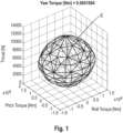
- An advantageous embodiment of the invention now provides for this 4D polytope to be approximated by a 4D hyperellipsoid with the best possible fit (e.g. according to the method of least squares). For illustration, reference is made to the description of the figures below, in particular Figure 1 .
- One possible aspect of the present invention now consists in calculating the current control limitations mentioned, e.g. on the basis of the hyperellipsoid representation explained above, and using them for the display.
- the aim is to dynamically display to the pilot the current remaining control margin for each of the four available degrees of freedom (here corresponding to roll, pitch, yaw and lift/total thrust).
- the control limitations for all axes can be calculated epoch by epoch.
- the two individual control limits (upper and lower control limitations) for each of the axes are obtained by determining the two intersection points of the line along the control axis through ⁇ Cmd with the hyperellipsoid in the 4-dimensional torque-thrust space.
- the assistance system according to the invention realizes the same inventive idea as one of the aforementioned methods.
- the assistance system according to the invention is configured to carry out one of the aforementioned methods.
- all of the aforementioned features, combinations of features and advantages can also be combined with the assistance system or apply to the assistance system.
- the assistance system is configured in particular to support a pilot in controlling an aircraft.
- the assistance system comprises at least one calculation device and one display device.
- the calculation device and the display device are preferably connected to each other in a signal-communicating manner. Independently of the aforementioned, the calculation device and the display device can be spatially spaced apart from each other or can be formed within a common apparatus.
- the calculation device is configured to calculate the momentary control limitations for controlling the aircraft about its roll axis, for controlling the aircraft about its pitch axis, for controlling the aircraft about its yaw axis and for controlling the total thrust of all propulsion devices.
- the calculation device can be, for example, a processor and/or a computer.
- the display device is configured to display the calculated control limitations, in particular the control limitations calculated by the calculation device.
- the display device can, for example, be a display, in particular a head-up display (HUD) and/or a touchpad with display functionality.
- HUD head-up display
- the assistance system comprises an input device.
- the input device is configured as a pilot control stick (PCS).
- PCS pilot control stick
- the input device can be directly or indirectly, connected and/or connectable to the calculation device in a signal-communicating manner.
- the input device can be indirectly connected to the calculation device via one or more other devices.
- the input device can be directly or indirectly connected and/or connectable to the display device in a signal-communicating manner.
- the input device can be indirectly connected to the display device via one or more other devices.
- the input device is connected and/or can be connected to the calculation device in a signaling-communicating manner.
- the calculation device can be connected and/or connectable to the display device in a signal-communicating manner.
- the input device can, for example, be configured to receive the pilot's control commands.
- the pilot's control commands received by the input device are then provided to the calculation device as control input, in particular as signals that correspond to the control input.
- the pilot's control commands can be measured from various sensors, for example a force sensor or position sensor or any other type, associated with the pilot control stick (PCS) where these sensor signals are then processed to generate the control input by the calculation device.
- PCS pilot control stick
- the calculation device can transmit the control input to the display device in modified and/or unmodified form.
- the calculation device can modify, in particular edit and/or process the control input as part of a control method.
- the control method can have a pseudo-control, so that the control method represents a type of mapping specification from control inputs and state towards pseudo-control.
- the aircraft according to the invention realises the same inventive idea as one of the aforementioned methods and/or one of the aforementioned assistance systems.
- the aircraft according to the invention preferably comprises one of the aforementioned assistance systems.
- all of the aforementioned features, combinations of features and advantages can also be realised/combined with or by the aircraft.
- the aircraft in addition to one of the aforementioned assistance systems, the aircraft comprises a plurality of lift-generating propulsion devices. At least one of the plurality of lift-generating propulsion devices comprises a rotor and an electric motor for driving the rotor. Preferably, each of the plurality of lift-generating propulsion devices comprises a rotor and an electric motor for driving the corresponding rotor.
- the propulsion devices are arranged and/or configured on the aircraft in such a way that the propulsion devices generate the lift necessary to maintain the aircraft in a substantially stationary hovering position.
- the propulsion devices are arranged and/or configured on the aircraft in such a way that the propulsion devices can generate a vertical lift force.
- Aspect 1 Method of assisting a pilot in controlling an aircraft having a plurality of lift-generating propulsion devices, the method comprising the following method steps, calculation of momentary control limitations for each: a control of the aircraft around its roll axis, a control of the aircraft around its pitch axis, a control of the aircraft around its yaw axis and a control of the total thrust T of all propulsion devices, and display of the calculated control limitations by a display device.
- Aspect 6 Method according to one of the preceding aspects, wherein at least one of the control limitations is displayed relative to a neutral control value.
- Aspect 7 Method according to one of the preceding aspects, wherein for at least one control limitation, preferably for all control limitations, an area within the corresponding control limitation is visually displayed differently than an area outside the corresponding control limitation.
- Aspect 8 Method according to one of the preceding aspects, wherein at least one of the control limitations, preferably all of the control limitations, has an upper control limit and a lower control limit.
- Aspect 10 Method according to one of the aspects 8 or 9, wherein the upper control limit and the lower control limit are shown as parallel lines within a display field.
- Aspect 11 Method according to one of the preceding aspects, wherein a momentary control value is displayed for the control of the aircraft about its roll axis, for the control of the aircraft about its pitch axis, for the control of the aircraft about its yaw axis and/or for the control of the total thrust T of all propulsion devices.
- Aspect 12 Method according to aspect 11, wherein the graphical representation of the momentary control value changes as soon as the momentary control value reaches the respective control limitation.
- Aspect 13 Method according to one of the preceding aspects, wherein the control of the aircraft is described by a vector comprising four components, namely the three components of a torque about the respective aircraft axes and the total thrust, wherein the three components of torque being dependent on the arrangement and the momentary thrust of the individual propulsion devices, and the momentary limitations of the vector with respect to each of the four components are determined to calculate the control limitations.
- Aspect 14 Assistance system for assisting a pilot in controlling an aircraft, the assistance system comprising: a calculation device for the calculation of momentary control limitations for each: a control of the aircraft around its roll axis, a control of the aircraft around its pitch axis, a control of the aircraft around its yaw axis and a control of the total thrust T of all propulsion devices, and a display device for displaying the calculated control limitations.
- Aspect 17 Assistance system according to one of the aspects 14 to 16, wherein the assistance system comprises an input device, preferably a joystick, wherein the input device is connected to the calculation device in a signaling-communicating manner and wherein the input device is configured to receive control commands from the pilot in order to provide the pilot's control commands to the calculation device as a control input.
- Aspect 18 Aircraft comprising an assistance system according to one of aspects 14 to 17, wherein the aircraft comprises a plurality of lift-generating propulsion devices.
- Aspect 19 Aircraft according to aspect 18, wherein each of the plurality of propulsion devices comprises a rotor and an electric motor for driving the corresponding rotor.
- Aspect 20 Aircraft according to one of the aspects 18 or 19, wherein the propulsion devices are arranged such that the propulsion devices generate a vertical lift force.
- Figure 1 shows the ellipsoid E as described above for an aircraft in a pseudo-3D representation in a torque-thrust space, in which one dimension, in this case the yaw torque, is specified in a fixed manner. Accordingly, the ellipsoid E symbolizes the currently available control volume in the remaining three spatial directions thrust, pitch torque and roll torque.
- the ellipsoid E describes the momentary control limitations of a flight state vector ⁇ (not shown in Figure 1 ), which - starting from a center point of the ellipsoid E - can only lie on its surface or in its interior.
- the vector ⁇ representing the state of the aircraft in terms of its pitch, roll, yaw and total thrust at a particular point of flight time and the vector ⁇ lying within the boundary or limits of the ellipsoid is desirable for a stable flight state.
- the control parameters lying within the ellipsoid will indicate the operable control volume of the aircraft for achieving stable flight conditions. Outside the interior of the ellipsoid defines the unstable and undesirable aircraft region.
- the interior of the ellipsoid E indicates the physically accessible control range of the aircraft, i.e. those flight states that the pilot can currently realize with the aircraft.
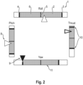
- Figure 2 shows a corresponding representation as can be generated, for example, by means of the method according to the invention and/or the assistance system 1, in particular the display device 29 (see Figure 5 ).
- the current control limitations of the control volume for each component of the flight condition vector ⁇ are dynamically displayed to the pilot.
- a fixed rectangular display area 2 is provided on a display 1 of the assistance system for each component, i.e. for each control parameter of the aircraft 20 in relation to the roll axis x, the pitch axis y and the yaw axis z (see Figure 5 ), which is only explicitly referred to for the roll moment.
- the displays respectively the display areas 2 for the individual components are arranged around a central display area 2a, in which central display area 2a further control-relevant displays may be presented (not shown).
- the dynamically calculated control value limitations for the relevant component are displayed in red (at 3 and 4), with one of these limitations indicating the possible lower limit for the relevant component and the other limit indicating the associated upper limit.
- Reference sign 5 shows the average value (mean value of lower limit 4 and upper limit 3).
- the area 6 between the limitations 3 and 4 is colored green and represents the physically achievable control range for the aircraft (in relation to the component in question).
- Reference sign 8 denotes a momentary control value which indicates the currently controlled value of the component of the relevant control limitation 3, 4, in particular with respect to the upper control limit 3 and the lower control limit 4.
- the momentary control value 8 is white, but changes color (limited momentary control value 9) when it approaches one of the control limitations 3, 4. This is shown symbolically in Figure 2 for the control in relation to the pitch axis ("pitch") and for the control in relation to the yaw axis ("yaw").
- the momentary control value 8 in relation to the pitch axis is still a long way away from the control limitations 3, 4.
- the limited momentary control value 9 in relation to the yaw axis (“yaw”) has already reached the left-hand control limit and is shown in a different color accordingly.
- the relevant limited momentary control value 9 is colored differently, preferably red, and is located at or on the relevant control limitation.
- the thrust is almost at or near its maximum possible value. Accordingly, the momentary control value of the thrust is positioned and also displayed differently.
- the frame of the momentary control value is somewhat thicker and the coloring can also be selected differently.
- the momentary control value can be colored yellow.
- control limitations 3 and 4 as well as the area 6 within the control limitations 3, 4 and the neutral control value 5 are movable dynamically within the (fixed) display fields 2, depending on the current flight status or pilot control command.
- the display within the display fields 2 does not have to be symmetrical with respect to the field boundaries (rectangular outline), especially for the thrust.
- the momentary control value 8 denotes a current commanded pitch torque (element of the 4x1 vector ⁇ ; not shown) on the aircraft fuselage or its display, which - like all other components - is provided at a preferably constant update rate, in particular by the aforementioned calculation device (see Figure 5 ), e.g. by a flight control law implemented there.
- the commanded roll, yaw and thrust value (also elements of the vector ⁇ ) is shown in the other three displays or display fields 2, as already described.
- the thick, preferably red, bars or lines indicate the current control limitation for the thrust according to reference sign 10. These bars (corresponding to the aforementioned limitations 3, 4) are continuously moving depending on the state of the aircraft and the pilot's inputs, thus increasing and decreasing the control volume on the respective axis. This also applies analogously to the displays for roll, pitch and yaw.
- the available control volume is preferably displayed in green (see hatched area described by the reference sign 11 in Figure 2 ).
- the corresponding area in relation to the control around the roll axis of the aircraft changes its size dynamically depending on the position of the limitation bars (control limitations 3, 4).
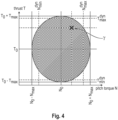
- Figure 4 shows a 2D representation illustrating the calculation of the dynamic limitations, as described mathematically in detail above.
- the scalar values N 0 and T 0 indicate the centre of the hyperellipsoid, which is located at the intersection of the two associated lines.
- the scalar values N max and T max describe the corresponding half-axis length of the hyperellipsoid E. The same applies to the other axes not shown here (roll and pitch).
- N max dyn N min dyn
- T max dyn T min dyn
- the momentary control limitation T max dyn and T min dyn for the thrust results by running from ⁇ parallel to the ordinate to the points of intersection with the ellipsoid E.
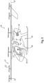
- FIG 5 schematically shows an example of an aircraft 20 in the form of an eVTOL.
- the aircraft 20 has a plurality of propulsion devices 21.
- Each of the propulsion devices 21 comprises a propeller or rotor 22 with a fixed pitch and an electric motor 23 for driving the rotor 22.
- the rotors 22 are all arranged in or parallel to a common level 24, with the rotor blades inclined relative to the level 24 or relative to a support structure (fixed pitch angle).
- the aircraft fuselage 25 including a cockpit is located below the level 24.
- a pilot 26 flies or controls the aircraft 20 by using an input device 27 in the form of a control stick 27.
- the aircraft 20 further comprises a calculation device 28.
- the calculation device 28 is connected to the input device 27 in a signal-communicating manner.
- Reference sign 29 denotes a display device, which in the embodiment example shown in Figure 5 is configured as a display (screen) 29.
- the display device 29 is in turn connected to the calculation device 28 in a signal-communicating manner.
- the calculation device 28, the input device 27 and the display device 29 together commonly form an assistance system 1.
- the calculation device 28 receives the corresponding control signals and can perform the calculations as part of the method described above.
- the dynamically calculated momentary control limitations can then be shown to the pilot 26 via the display 29.
Landscapes
- Engineering & Computer Science (AREA)
- Aviation & Aerospace Engineering (AREA)
- Radar, Positioning & Navigation (AREA)
- Remote Sensing (AREA)
- Physics & Mathematics (AREA)
- General Physics & Mathematics (AREA)
- Automation & Control Theory (AREA)
- Traffic Control Systems (AREA)
Applications Claiming Priority (1)
| Application Number | Priority Date | Filing Date | Title |
|---|---|---|---|
| DE102023130995.1A DE102023130995B3 (de) | 2023-11-08 | 2023-11-08 | Verfahren zur Unterstützung eines Piloten bei der Steuerung eines Luftfahrzeugs, Assistenzsystem für einen Luftfahrzeugpiloten, und Luftfahrzeug |
Publications (1)
| Publication Number | Publication Date |
|---|---|
| EP4553603A1 true EP4553603A1 (fr) | 2025-05-14 |
Family
ID=92895540
Family Applications (1)
| Application Number | Title | Priority Date | Filing Date |
|---|---|---|---|
| EP24202046.9A Pending EP4553603A1 (fr) | 2023-11-08 | 2024-09-23 | Procédé d'assistance d'un pilote pour commander un aéronef, système d'assistance pour un pilote d'aéronef et aéronef |
Country Status (4)
| Country | Link |
|---|---|
| US (1) | US20250146839A1 (fr) |
| EP (1) | EP4553603A1 (fr) |
| CN (1) | CN119960480A (fr) |
| DE (1) | DE102023130995B3 (fr) |
Families Citing this family (2)
| Publication number | Priority date | Publication date | Assignee | Title |
|---|---|---|---|---|
| US20250198799A1 (en) * | 2023-12-18 | 2025-06-19 | The Charles Stark Draper Laboratory, Inc. | Display technologies |
| CN120740378B (zh) * | 2025-08-20 | 2025-11-28 | 奥瑞思智能科技(天津)有限公司 | 一种靶机远程协同控制的人机交互指令生成方法 |
Citations (2)
| Publication number | Priority date | Publication date | Assignee | Title |
|---|---|---|---|---|
| US20130134255A1 (en) * | 2011-07-12 | 2013-05-30 | Bell Helicopter Textron Inc. | Pilot cyclic control margin display |
| CN114056554A (zh) * | 2020-08-04 | 2022-02-18 | 沃科波特有限公司 | 飞行器、飞行控制装置和确定飞行器中的机动储备的方法 |
Family Cites Families (6)
| Publication number | Priority date | Publication date | Assignee | Title |
|---|---|---|---|---|
| JPH062190B2 (ja) * | 1987-04-24 | 1994-01-12 | 双葉電子工業株式会社 | ラジコン送信機 |
| WO2013174751A2 (fr) * | 2012-05-21 | 2013-11-28 | E-Volo Gmbh | Procédé de commande d'un appareil volant sous forme d'un multicoptère et système de commande correspondant |
| EP3170746A1 (fr) * | 2015-11-19 | 2017-05-24 | HW Aviation AG | Procede de commande d'un multicoptere et dispositifs d'execution du procede |
| DE102018129211A1 (de) * | 2018-11-20 | 2020-05-20 | Volocopter Gmbh | Bus-System zur elektrischen Versorgung einer Mehrzahl von Lasten und hiermit ausgestattetes Fluggerät |
| DE102020200056B4 (de) * | 2020-01-07 | 2025-08-14 | Volkswagen Aktiengesellschaft | Kontrolleinheit zur kontinuierlichen Steuersignalüberprüfung bei Multirotorfluggeräten vor und während eines Flugbetriebs |
| DE102021111104B4 (de) * | 2021-04-29 | 2024-08-29 | Volocopter Gmbh | Verfahren und Steuereinheit zum Steuern eines überbestimmten Systems, System und Luftfahrzeug |
-
2023
- 2023-11-08 DE DE102023130995.1A patent/DE102023130995B3/de active Active
-
2024
- 2024-09-19 US US18/890,417 patent/US20250146839A1/en active Pending
- 2024-09-23 EP EP24202046.9A patent/EP4553603A1/fr active Pending
- 2024-11-08 CN CN202411593431.3A patent/CN119960480A/zh active Pending
Patent Citations (2)
| Publication number | Priority date | Publication date | Assignee | Title |
|---|---|---|---|---|
| US20130134255A1 (en) * | 2011-07-12 | 2013-05-30 | Bell Helicopter Textron Inc. | Pilot cyclic control margin display |
| CN114056554A (zh) * | 2020-08-04 | 2022-02-18 | 沃科波特有限公司 | 飞行器、飞行控制装置和确定飞行器中的机动储备的方法 |
Also Published As
| Publication number | Publication date |
|---|---|
| DE102023130995B3 (de) | 2025-02-06 |
| US20250146839A1 (en) | 2025-05-08 |
| CN119960480A (zh) | 2025-05-09 |
Similar Documents
| Publication | Publication Date | Title |
|---|---|---|
| EP4553603A1 (fr) | Procédé d'assistance d'un pilote pour commander un aéronef, système d'assistance pour un pilote d'aéronef et aéronef | |
| US20250019090A1 (en) | Dynamic flight envelope protection and degraded flight state operations in a vehicle control and interface system | |
| Lombaerts et al. | Control concepts for simplified vehicle operations of a quadrotor eVTOL vehicle | |
| EP3370129B1 (fr) | Lissage de la transition du mode de commande d'un giravion | |
| US9383756B2 (en) | Automatic flight control method for a rotorcraft enabling the rotorcraft to maintain a path by tracking manual flight controls | |
| US20050004721A1 (en) | Constant vertical state maintaining cueing system | |
| EP3357809B1 (fr) | Système et procédé de stabilisation d'une accélération longitudinale d'un giravion | |
| US20240053770A1 (en) | Vehicle control loops and interfaces | |
| CN121605070A (zh) | 用于evtol航空器的控制裕度显示的系统和方法 | |
| WO2025116984A2 (fr) | Gestion d'urgence automatisée et assistée par utilisateur pour véhicule aérien | |
| EP3805893B1 (fr) | Procédé de commande d'un système d'actionneur et aéronef l'utilisant | |
| CN106662870A (zh) | 用于生成飞行器的结果设定点轨迹的方法及设备、相关计算机程序产品及飞行器 | |
| EP0743244A1 (fr) | Système de protection contre survitesse pour autopilote/directeur de vol | |
| EP3599160B1 (fr) | Système et procédé de commande de vol de giravion | |
| US11983017B2 (en) | Method for determining a maneuvering reserve in an aircraft, flight control device in an aircraft and appropriately equipped aircraft | |
| EP3613671B1 (fr) | Lissage de transition de mode de commande de giravion | |
| US20200031490A1 (en) | System and Method for Tail Rotor Margin Awareness | |
| JPH09510933A (ja) | 対気速度を制御するヘリコプターの自動操縦装置 | |
| US11136136B2 (en) | System and method for flight mode annunciation | |
| EP3677505B1 (fr) | Système et procédé de commande d'hélicoptère | |
| EP2546141B1 (fr) | Système et procédé de limitation des entrées de contrôle cycliques | |
| CN116685527B (zh) | 用于能够悬停的飞行器的指示器和用于辅助执行所述飞行器的操作的方法 | |
| RU2716886C1 (ru) | Командно-пилотажный индикатор | |
| EP3575213A1 (fr) | Système et procédé de commande d'hélicoptère | |
| Kaneshige et al. | Simplified vehicle control concept for a lift plus cruise evtol vehicle |
Legal Events
| Date | Code | Title | Description |
|---|---|---|---|
| PUAI | Public reference made under article 153(3) epc to a published international application that has entered the european phase |
Free format text: ORIGINAL CODE: 0009012 |
|
| STAA | Information on the status of an ep patent application or granted ep patent |
Free format text: STATUS: THE APPLICATION HAS BEEN PUBLISHED |
|
| AK | Designated contracting states |
Kind code of ref document: A1 Designated state(s): AL AT BE BG CH CY CZ DE DK EE ES FI FR GB GR HR HU IE IS IT LI LT LU LV MC ME MK MT NL NO PL PT RO RS SE SI SK SM TR |
|
| 19U | Interruption of proceedings before grant |
Effective date: 20250301 |
|
| 19W | Proceedings resumed before grant after interruption of proceedings |
Effective date: 20250801 |
|
| RAP3 | Party data changed (applicant data changed or rights of an application transferred) |
Owner name: VOLOCOPTER TECHNOLOGIES GMBH |
|
| STAA | Information on the status of an ep patent application or granted ep patent |
Free format text: STATUS: REQUEST FOR EXAMINATION WAS MADE |
|
| 17P | Request for examination filed |
Effective date: 20251021 |
|
| GRAP | Despatch of communication of intention to grant a patent |
Free format text: ORIGINAL CODE: EPIDOSNIGR1 |
|
| STAA | Information on the status of an ep patent application or granted ep patent |
Free format text: STATUS: GRANT OF PATENT IS INTENDED |
|
| RIC1 | Information provided on ipc code assigned before grant |
Ipc: G05D 1/82 20240101AFI20260225BHEP Ipc: G01C 1/00 20060101ALI20260225BHEP Ipc: B64C 13/00 20060101ALI20260225BHEP Ipc: G01C 23/00 20060101ALI20260225BHEP Ipc: G05D 105/22 20240101ALI20260225BHEP Ipc: G05D 109/25 20240101ALI20260225BHEP |
|
| INTG | Intention to grant announced |
Effective date: 20260311 |