EP4553626A1 - Dispositif électronique pour améliorer la sensibilité d'entrée tactile et procédé de fonctionnement associé - Google Patents
Dispositif électronique pour améliorer la sensibilité d'entrée tactile et procédé de fonctionnement associé Download PDFInfo
- Publication number
- EP4553626A1 EP4553626A1 EP23868389.0A EP23868389A EP4553626A1 EP 4553626 A1 EP4553626 A1 EP 4553626A1 EP 23868389 A EP23868389 A EP 23868389A EP 4553626 A1 EP4553626 A1 EP 4553626A1
- Authority
- EP
- European Patent Office
- Prior art keywords
- electronic device
- capacitor
- switch
- frequencies
- khz
- Prior art date
- Legal status (The legal status is an assumption and is not a legal conclusion. Google has not performed a legal analysis and makes no representation as to the accuracy of the status listed.)
- Pending
Links
Images


Classifications
-
- G—PHYSICS
- G06—COMPUTING OR CALCULATING; COUNTING
- G06F—ELECTRIC DIGITAL DATA PROCESSING
- G06F3/00—Input arrangements for transferring data to be processed into a form capable of being handled by the computer; Output arrangements for transferring data from processing unit to output unit, e.g. interface arrangements
- G06F3/01—Input arrangements or combined input and output arrangements for interaction between user and computer
- G06F3/03—Arrangements for converting the position or the displacement of a member into a coded form
- G06F3/041—Digitisers, e.g. for touch screens or touch pads, characterised by the transducing means
- G06F3/0416—Control or interface arrangements specially adapted for digitisers
- G06F3/0418—Control or interface arrangements specially adapted for digitisers for error correction or compensation, e.g. based on parallax, calibration or alignment
- G06F3/04186—Touch location disambiguation
-
- G—PHYSICS
- G06—COMPUTING OR CALCULATING; COUNTING
- G06F—ELECTRIC DIGITAL DATA PROCESSING
- G06F3/00—Input arrangements for transferring data to be processed into a form capable of being handled by the computer; Output arrangements for transferring data from processing unit to output unit, e.g. interface arrangements
- G06F3/01—Input arrangements or combined input and output arrangements for interaction between user and computer
- G06F3/03—Arrangements for converting the position or the displacement of a member into a coded form
- G06F3/041—Digitisers, e.g. for touch screens or touch pads, characterised by the transducing means
- G06F3/0416—Control or interface arrangements specially adapted for digitisers
- G06F3/0418—Control or interface arrangements specially adapted for digitisers for error correction or compensation, e.g. based on parallax, calibration or alignment
- G06F3/04182—Filtering of noise external to the device and not generated by digitiser components
-
- G—PHYSICS
- G06—COMPUTING OR CALCULATING; COUNTING
- G06F—ELECTRIC DIGITAL DATA PROCESSING
- G06F3/00—Input arrangements for transferring data to be processed into a form capable of being handled by the computer; Output arrangements for transferring data from processing unit to output unit, e.g. interface arrangements
- G06F3/01—Input arrangements or combined input and output arrangements for interaction between user and computer
- G06F3/03—Arrangements for converting the position or the displacement of a member into a coded form
- G06F3/041—Digitisers, e.g. for touch screens or touch pads, characterised by the transducing means
- G06F3/0416—Control or interface arrangements specially adapted for digitisers
- G06F3/04166—Details of scanning methods, e.g. sampling time, grouping of sub areas or time sharing with display driving
-
- G—PHYSICS
- G06—COMPUTING OR CALCULATING; COUNTING
- G06F—ELECTRIC DIGITAL DATA PROCESSING
- G06F3/00—Input arrangements for transferring data to be processed into a form capable of being handled by the computer; Output arrangements for transferring data from processing unit to output unit, e.g. interface arrangements
- G06F3/01—Input arrangements or combined input and output arrangements for interaction between user and computer
- G06F3/03—Arrangements for converting the position or the displacement of a member into a coded form
- G06F3/041—Digitisers, e.g. for touch screens or touch pads, characterised by the transducing means
- G06F3/044—Digitisers, e.g. for touch screens or touch pads, characterised by the transducing means by capacitive means
-
- H—ELECTRICITY
- H03—ELECTRONIC CIRCUITRY
- H03K—PULSE TECHNIQUE
- H03K17/00—Electronic switching or gating, i.e. not by contact-making and –breaking
- H03K17/94—Electronic switching or gating, i.e. not by contact-making and –breaking characterised by the way in which the control signals are generated
- H03K17/96—Touch switches
- H03K17/962—Capacitive touch switches
- H03K17/9622—Capacitive touch switches using a plurality of detectors, e.g. keyboard
-
- H—ELECTRICITY
- H03—ELECTRONIC CIRCUITRY
- H03K—PULSE TECHNIQUE
- H03K2217/00—Indexing scheme related to electronic switching or gating, i.e. not by contact-making or -breaking covered by H03K17/00
- H03K2217/94—Indexing scheme related to electronic switching or gating, i.e. not by contact-making or -breaking covered by H03K17/00 characterised by the way in which the control signal is generated
- H03K2217/96—Touch switches
- H03K2217/9607—Capacitive touch switches
- H03K2217/960705—Safety of capacitive touch and proximity switches, e.g. increasing reliability, fail-safe
-
- H—ELECTRICITY
- H03—ELECTRONIC CIRCUITRY
- H03K—PULSE TECHNIQUE
- H03K2217/00—Indexing scheme related to electronic switching or gating, i.e. not by contact-making or -breaking covered by H03K17/00
- H03K2217/94—Indexing scheme related to electronic switching or gating, i.e. not by contact-making or -breaking covered by H03K17/00 characterised by the way in which the control signal is generated
- H03K2217/96—Touch switches
- H03K2217/9607—Capacitive touch switches
- H03K2217/96071—Capacitive touch switches characterised by the detection principle
- H03K2217/960715—Rc-timing; e.g. measurement of variation of charge time or discharge time of the sensor
Definitions
- An embodiment of the present disclosure relates to an electronic device for improving touch input sensitivity and a method of operating the same.
- User interfaces are included in various electronic devices to allow interactions between users and the electronic devices.
- the Ul may be included in electronic devices such as home appliances (e.g., ovens, inductions, microwaves, refrigerators, washing machines, air conditioners, dish washers, and garment care devices), vehicles, mobile phones, etc.
- An example of a user interface is a touch based Ul.
- the touch based Ul is configured to receive an input of the user through a touch button (or touch sensor).
- the touch based Ul may receive the input of the user by determining whether a touch input has occurred based on a change in a capacitance of a capacitor coupled with to the touch button. For example, when no touch input occurs (or no touch input is detected), the capacitance of the capacitor coupled with the touch button may be C1 (an intrinsic capacitance or an intrinsic parasitic capacitance). When a touch input occurs (or a touch input is detected), the capacitance of the capacitor coupled with the touch button may be C1 + Cf (capacitance of a finger or capacitance of a touch pen).
- the touch based UI uses a fixed operating frequency (or a clock frequency) to charge or discharge the capacitor coupled with the touch button. Consequently, when incoming noise from outside (e.g., a power line) has a frequency (e.g., 6 megahertz(MHz) on 220 volts(V) power supply with direct current (DC)+3V) almost similar to the operating frequency, the noise may be introduced to the capacitance of the capacitor coupled with the touch button within the corresponding frequency band (e.g., 6 MHz).
- the electronic device may erroneously determine a touch input to the touch button. For example, when the noise is introduced to the capacitance of the capacitor coupled with the touch button, the electronic device may erroneously determine that a touch input occurs even though there is no occurrence of the touch input on the touch button.
- an electronic device may include a user interface and at least one processor.
- the user interface may include at least one touch button, a capacitor coupled with the at least one touch button, and a switch, coupled between the at least one touch button and the capacitor, configured to charge or discharge the capacitor.
- the at least one processor may be configured to spread an operating frequency into a certain number of frequencies in a certain frequency range.
- the at least one processor may control the switch to be turned on or off to charge or discharge the capacitor based on the spread frequencies.
- the at least one processor may measure a charging time of the capacitor according to the turning on or off of the switch.
- the at least one processor may determine whether a touch input occurs on the touch button based on the measured charging time.
- a method of operating an electronic device including a user interface including at least one touch button, a capacitor coupled with the at least one touch button and a switch, coupled between the at least one touch button and the capacitor, configured to charge or discharge the capacitor, and at least one processor may include spreading an operating frequency into a certain number of frequencies in a certain frequency range.
- the method of operating the electronic device may include controlling the switch to be turned on or off to charge or discharge the capacitor based on the spread frequencies.
- the method of operating the electronic device may include measuring a charging time of the capacitor according to the turning on or off of the switch.
- the method of operating the electronic device may include determining whether a touch input on the touch button has occurred, based on the measured charging time.
- the expression "at least one of a, b or c" indicates only a, only b, only c, both a and b, both a and c, both b and c, all of a, b, and c, or variations thereof.
- the expression “and/or” may be interpreted to include a combination or any of multiple elements.
- terms like “first”, “second”, or the like may be simply used to distinguish an element from another, without limiting the elements in a certain sense (e.g., in terms of importance or order).
- unit may each represent a unit for handling at least one function or operation, and may be implemented in hardware such as, but not limited to, a field programming gate array (FPGA) or application specific integrated circuit (ASIC), software, or a combination thereof.
- the term “unit” as used herein may not exclusively refer to software or hardware.
- the unit may be configured to be in an addressable storage medium and to execute one or more processors.
- the unit may include components, such as software components, object-oriented software components, class components and task components, processes, functions, attributes, procedures, subroutines, segments of program codes, drivers, firmware, microcodes, circuits, data, databases, data structures, tables, arrays, and variables. Functions provided through certain components or certain units may be combined to reduce the number or divided into additional components.
- the unit may include one or more processors.
- respective blocks and combinations of the blocks in flowcharts may be performed by computer program instructions.
- the computer program instructions may be loaded onto a processor of a universal computer, a special computer or other programmable data processing equipment. Instructions performed by the processor of a computer or other programmable data processing equipment may generate means for performing functions as described in the block(s) of the flowchart.
- the computer program instructions may also be stored in a computer-usable or computer-readable memory that may be oriented to a computer or other programmable data processing equipment to implement a function in a certain manner.
- the instructions stored in the computer-usable or computer-readable memory may also produce a manufactured item that may include instruction means for performing the function as described in the block(s) of the flowchart.
- the computer program instructions may also be loaded onto a computer or other programmable data processing equipment.
- each block of the flowchart may represent a part of a module, segment, or codes including one or more executable instructions to perform particular logic function(s).
- the functions recited in the blocks occur out of the sequence. For example, two successive blocks may be performed at substantially the same time or in reverse order depending on the corresponding functions.
- an electronic device for improving sensitivity of a touch button and a method of operating the electronic device may be provided.
- an electronic device for improving sensitivity of a touch button by controlling charging or discharging of a capacitor coupled with the touch button, and a method of operating the electronic device may be provided.
- an electronic device that is able to prevent an erroneous decision of a touch input due to noise by spreading an operating frequency for charging or discharging the capacitor coupled with the touch button, and a method of operating the electronic device may be provided.
- the term “wrong decision” as used herein may also be interchangeably used with misrecognition or misidentification.
- the electronic device may correctly determine whether a touch input occurs on the touch button even when noise having almost a similar frequency to the operating frequency comes in from outside (e.g., a power line).
- the spreading of the operating frequency may refer to spreading n (e.g., 2 to 32) frequencies in a frequency range of the fixed operating frequency ⁇ X (e.g., 2 to 10%). This may refer to using frequencies into which the fixed operating frequency (or clock frequency) is spread by a spread spectrum clock (SSC) to determine whether a touch input occurs in the electronic device.
- SSC spread spectrum clock
- 'X' and 'n' may be determined based on, but not limited to, at least one of a specification of the electronic device (e.g., power consumption of the electronic device, operation speed of the processor, and a resource of the electronic device for carrying out an embodiment of the present disclosure) and an amount of noise (e.g., noise in a frequency band of 100 kHz to 200 MHz) likely to be introduced to the electronic device.
- the noise likely to be introduced may be harmonic noise in a certain band (e.g., 6 MHz), without being limited thereto.
- the amount of noise likely to be introduced to an electronic device may be measured based on a charging time of a capacitor C1.
- the amount of noise likely to be introduced may be measured according to a value by which a first difference value d1 exceeds a second difference value d2.
- the measuring of the amount of noise likely to be introduced to the electronic device is not limited to what are described above.
- the amount of noise likely to be introduced to the electronic device may be measured based on a time value by which the charging time t (or current charging time) of the capacitor C1 measured while a touch input occurs exceeds the normal charging time t2 of the capacitor C1 while a normal touch input occurs.
- the exceeding time value increases, the amount of noise likely to be introduced may increase, and when the exceeding time value decreases, the amount of noise likely to be introduced may be reduced.
- FIG. 1 is a diagram for describing an electronic device 100 according to an embodiment of the present disclosure.
- the electronic device 100 may be at least one of electronic devices such as a home appliance (e.g., an oven, an induction, a microwave, a refrigerator, a washing machine, an air conditioner, a dishwasher, or a garment care device), a vehicle or a cell phone, without being limited thereto.
- a home appliance e.g., an oven, an induction, a microwave, a refrigerator, a washing machine, an air conditioner, a dishwasher, or a garment care device
- vehicle or a cell phone without being limited thereto.
- the electronic device 100 shown in FIG. 1 may include a touch based user interface 110 and a processor 120, but is not limited thereto.
- the electronic device 100 may include such components as shown in FIG. 4 or 5 , which will be described later, and may also include an analog-to-digital converter (ADC) between the user interface 110 and the processor 120.
- ADC analog-to-digital converter
- the user interface 110 may include a touch panel 30.
- the touch panel 30 may also be referred to as a touch screen panel or a touch screen.
- the processor 120 may consist of multiple processors and may therefore be referred to as at least one processor.
- the touch panel 30 is configured in a capacitance method.
- the touch panel 30 may include a touch button 10, a capacitor C1 coupled with the touch button 10, and a switch 20 for charging or discharging the capacitor C1, but is not limited thereto.
- the charging or discharging of the capacitor C1 may refer to charging or discharging the capacitor C1.
- the touch panel 30 may include a plurality of touch buttons 10, a plurality of capacitors C1 coupled with the plurality of touch buttons 10, respectively, and a plurality of switches 20 for charging or discharging the plurality of capacitors C1, respectively.
- the plurality may be represented as X x Y, where X and Y are each in the range of 1 to n, and n is a natural number equal to or larger than 2, but is not limited thereto.
- the touch panel 30 may be described as including at least one touch button 10, at least one capacitor C1 corresponding to the at least one touch button 10, and at least one switch 20 corresponding to the at least one capacitor C1.
- the user interface 110 may receive a user input through the at least one touch button 10.
- the user input may be received when a finger 5 of the user approaches or touches the touch button 10.
- the user input may be referred to as a touch input that occurs when the finger 5 of the user approaches or touches the touch button 10.
- the receiving of the user input may also be expressed as a touch input occurring.
- what approaches or touches the touch button 10 is illustrated as the finger 5 of the user in an embodiment of the present disclosure, but is not limited thereto. For example, even when a capacitive touch pen approaches or touches the touch button 10, the user interface 110 may receive the user input.
- the user interface 110 may be described as including the at least one touch button 10. It may be described that the user interface 110 may include at least one touch button 10, at least one capacitor C1 corresponding to the at least one touch button 10, and the switch 20 for charging or discharging the at least one capacitor C1.
- the user interface 110 may be described as including the touch panel 30 including the at least one touch button 10. It may be described that the user interface 110 may include the touch panel 30 including at least one touch button 10, at least one capacitor C1 corresponding to the at least one touch button 10, and the switch 30 corresponding to the at least one capacitor C1.
- the switch 20 may be coupled between a power source Vcc and the capacitor C1 and turned on or off to charge or discharge the capacitor C1.
- the user interface 110 may include the at least one touch button 10, the capacitor C1 coupled with the at least one touch button 10, and the switch 20, coupled between the at least one touch button 10 and the capacitor C1, configured to charge or discharge the capacitor C1.
- the touch button 10 may detect approaching or touching of the finger 5 of the user.
- the touch button 10 may also be referred to as a touch sensor for detecting approaching or touching of the finger 5 of the user.
- the touch button 10 may have a structure of being mapped to a touch sensor.
- the finger 5 of the user may also be referred to as a body part of the user, but is not limited thereto.
- the touch button 10 may detect approximating or touching of a capacitive touch pen other than the finger 5 of the user.
- the touch button 10 may be configured by coating a special conductive metal material, tin antimony oxide (TAO), on both sides of a substrate to form a transparent electrode (indium tin oxide (IOT)), allowing a certain amount of current to flow on the glass surface.
- TAO tin antimony oxide
- IOT indium tin oxide
- the transparent electrode may be formed with a film or glass.
- the transparent electrode may be formed such that the X-axis and the Y-axis cross each other.
- the switch 20 may be coupled between the power source Vcc and the capacitor C1 and may be controlled by the processor 120 to be turned on or off.
- the switch 20 may be turned on or turned off according to a control signal sent from the processor 120.
- the capacitor C1 may be charged or discharged depending on whether the switch 20 is turned on or off.
- the control signal transmitted from the processor 120 may be based on a certain number of frequencies into which an operating frequency of the switch 20 may be spread within a certain frequency range.
- the switch 20 may be described as being turned on or off based on the certain number of frequencies into which the operating frequency is spread within the certain frequency range.
- the processor 120 may measure the charging time t of the capacitor C1 according to the switch 20 being turned on or off.
- the measuring of the charging time t of the capacitor C1 may be described as obtaining a charging time t1 of the capacitor C1.
- the measuring of the charging time t of the capacitor C1 may be described as measuring capacitance C of the capacitor C1. This is because the capacitance of the capacitor C1 may be proportional to the charging time t of the capacitor C1.
- the charging time t of the capacitor C1 may be represented by a value obtained by counting the time taken for a voltage corresponding to the capacitance of the capacitor C1 to reach a reference voltage, which may be referred to as the RC (Resistance-Capacitance) delay time.
- the reference voltage may be a voltage when the capacitance of the capacitor C1 is C1
- the reference voltage may be a voltage when the capacitance of the capacitor C1 is C1+Cf (or C1+Cf').
- the charging time (RC delay time) of the capacitor C1 may increase as well.
- the charging time of the capacitor C1 may also be represented by a raw count or real-time sensing value for the touch button 10.
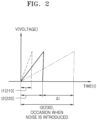
- FIG. 2 is a diagram for describing a charging time of the capacitor C1 included in the touch panel 30 in the electronic device 100, according to an embodiment of the present disclosure.
- the normal charging time t2 of the capacitor C1 when a normal touch input occurs through the touch button 10 may be measured as shown in 220 of FIG. 2 . As shown in 210 and 220 of FIG.
- a measured charging time t3 of the capacitor C1 is longer than the normal charging time t2 of the capacitor C1 by a first time ⁇ t based on a normal touch input occurring on the touch button 10 as shown in 230 of FIG. 2 .
- the first time ⁇ t may be determined depending on the amount of the introduced noise. For example, that the larger the amount of the introduced noise is, the longer the first time ⁇ t may be, and the smaller the amount of the introduced noise is, the shorter the first time ⁇ t may be.
- a certain frequency range and a certain number of frequencies may be determined depending on the amount of noise likely to be introduced to the electronic device 100.
- the certain frequency range may be equal to the operating frequency ⁇ 10%, and the certain number of frequencies may be 16.
- the certain frequency range may be the operating frequency ⁇ 12%, and the certain number of frequencies may be 18.
- the certain frequency range may be the operating frequency ⁇ 8%, and the certain number of frequencies may be 14.
- the amount of noise likely to be introduced to the electronic device 100, the certain frequency range and the certain number of frequencies are not limited thereto.
- FIG. 3 is a diagram illustrating an example of spreading the operating frequency in the electronic device 100, according to an embodiment of the present disclosure.
- FIG. 3 shows a case that the operating frequency at which to control the switch 20 to be turned on or off is 150 kHz.
- the operating frequency may be one fixed in the electronic device 100 at first.
- the processor 120 included in the electronic device 100 may spread the operating frequency into a certain number (e.g., 16) of frequencies within a certain frequency range (e.g., the operating frequency ⁇ 10%) to control the switch 20 to be turned on or off.
- Information regarding the certain frequency range and the certain number of spread frequencies may be stored in the memory 130 included in the electronic device 100 and may be read out and used by the processor 120, but the present disclosure is not limited thereto.
- the processor 120 may be configured to spread the operating frequency into a certain number of frequencies within a certain frequency range.
- the certain frequency range and the certain number may be dynamically set according to an amount of noise likely to be introduced to the electronic device 100.
- the electronic device 100 may store, in the memory 130, information about a frequency range and the number of frequencies, at least one of which may be increased more than the example shown in FIG. 3 .
- the electronic device 100 may use the information about the frequency range and the number of frequencies stored in the memory 130 to spread the operating frequency.
- the electronic device 100 may store information about the frequency range increased by ⁇ 2 KHz more than the example shown in FIG. 3 in the memory 130 and use the information to spread the operating frequency.
- the electronic device 100 may store information about the number of frequencies increased by two(2) more than the example shown in FIG. 3 in the memory 130 and use the information to spread the operating frequency.
- the electronic device 100 may store information about an increase by ⁇ 2 kHz more than the example shown in FIG. 3 and an increase of the number of frequencies by two(2) more than the example shown in FIG. 3 in the memory 130 and use the information to spread the operating frequency.
- the amount of noise likely to be introduced to the electronic device 100 is smaller than the amount of noise during the charging time t3 230 shown in FIG. 2 , so the electronic device 100 may store information about at least one of the frequency range or the number of frequencies reduced further than the example shown in FIG. 3 in the memory 130 and use the information to spread the operating frequency.
- the electronic device 100 may store information about a decrease by ⁇ 2 kHz further than the example shown in FIG. 3 in the memory 130 and use the information to spread the operating frequency.
- the electronic device 100 may store information about the number of frequencies reduced by two(2) less than the example shown in FIG. 3 in the memory 130 and use the information to spread the operating frequency. For example, information about a decrease by ⁇ 2 kHz further than the example shown in FIG. 3 and a decrease of the number of frequencies by two(2) less than the example shown in FIG. 3 may be stored in the memory 130 and used to spread the operating frequency.
- the processor 120 of the electronic device 100 may spread the operating frequency 150 kHz into eight(8) frequencies between 135 kHz to 150 kHz and eight(8) frequencies between 150 kHz to 165 kHz based on the operating frequency of 150 kHz.
- the processor 120 may spread the operating frequency into eight(8) frequencies (e.g., 135 kHz, 137 kHz, 139 kHz, 141 kHz, 143 kHz, 145 kHz, 147 kHz and 149 kHz), and another eight(8) frequencies (e.g., 151 kHz, 153 kHz, 155 kHz, 157 kHz, 159 kHz, 161 kHz, 163 kHz and 165 kHz) with gaps of 2 kHz.
- frequencies e.g., 135 kHz, 137 kHz, 139 kHz, 141 kHz, 143 kHz, 145 kHz, 147 kHz and 149 kHz
- another eight(8) frequencies e.g., 151 kHz, 153 kHz, 155 kHz, 157 kHz, 159 kHz, 161 kHz, 163 kHz and 165 kHz
- the electronic device 100 may control the switch 20 to be turned on or off by switching between the spread 16 frequencies.
- 16 frequencies include the eight (8) frequencies (e.g., 135 kHz, 137 kHz, 139 kHz, 141 kHz, 143 kHz, 145 kHz, 147 kHz and 149kHz), and the other eight (8) frequencies (e.g., 151 kHz, 153 kHz, 155 kHz, 157 kHz, 159 kHz, 161 kHz, 163 kHz and 165 kHz), the processor 120 may control the switch 20 to be turned on or off based on a frequency of 165 kHz.
- the processor 120 may control the switch 20 to be turned on or off based on a frequency of 165 kHz.
- the processor 120 may then control the switch 20 to be turned on or off based on a frequency of 163 kHz.
- the processor 120 may then control the switch 20 to be turned on or off based on a frequency of 161 kHz.
- the processor 120 may then control the switch 20 to be turned on or off based on a frequency of 159 kHz.
- the processor 120 may then control the switch 20 to be turned on or off based on a frequency of 157 kHz.
- the processor 120 may then control the switch 20 to be turned on or off based on a frequency of 155 kHz.
- the processor 120 may then control the switch 20 to be turned on or off based on a frequency of 153 kHz.
- the processor 120 may then control the switch 20 to be turned on or off based on a frequency of 151 kHz.
- the processor 120 may then control the switch 20 to be turned on or off based on a frequency of 149 kHz.
- the processor 120 may then control the switch 20 to be turned on or off based on a frequency of 147 kHz.
- the processor 120 may then control the switch 20 to be turned on or off based on a frequency of 145 kHz.
- the processor 120 may then control the switch 20 to be turned on or off based on a frequency of 143 kHz.
- the processor 120 may then control the switch 20 to be turned on or off based on a frequency of 141 kHz.
- the processor 120 may then control the switch 20 to be turned on or off based on a frequency of 139 kHz. The processor 120 may then control the switch 20 to be turned on or off based on a frequency of 137 kHz. The processor 120 may then control the switch 20 to be turned on or off based on a frequency of 135 kHz.
- the switching between the spread frequencies is not limited to the sequential switching as described above.
- the processor 120 may use one frequency multiple times to control the switch 20 to be turned on or off.
- the processor 120 may use a frequency of 165 kHz multiple times (e.g., three to eight times) to control the switch 20 to be turned on or off.
- the processor 120 may sequentially switch and use frequencies from 163 kHz to 135 kHz multiple times (e.g., three to eight times) to control the switch 20 to be turned on or off.
- the processor 120 may control the switch 20 to be turned on or off based on frequencies from 135 kHz to 165 kHz that are switched sequentially in a reverse order to what is described above.
- the processor 120 may control the switch 20 to be turned on or off based on the spread frequency (or a clock frequency), and measure the charging time t of the capacitor C1 according to the turning on or off of the switch 20.
- the processor 120 controlling the switch 20 to be turned on or off based on the spread frequency may be said that the processor 120 controls the switch 20 to be turned on or off by transmitting a control signal that is based on the spread frequency to the switch 20.
- the measured charging time t of the capacitor C1 may be an average value of a certain number of charging times of the capacitor C1, which may be measured according to turning on or off of the switch 20 based on a certain number of frequencies. For example, in a case of controlling the switch 20 to be turned on or off by using 16 frequencies, the processor 12 may obtain an average value of 16 measured charging times of the capacitor C1 as the measured charging time t (or a current charging time) of the capacitor C1.
- the processor 120 may compare the obtained first difference value d1 with a threshold value.
- the processor 120 may determine that a touch input occurs on the touch button 10.
- the processor 120 may determine that no touch input occurs on the touch button 10.
- the processor 120 may include at least one of a central processing unit (CPU), a graphics processing unit (GPU), an accelerated processing unit (APU), a many integrated core (MIC), a digital signal processor (DSP) or a neural processing unit (NPU).
- the processor 120 may be implemented in the form of a system on chip (SoC) with one or more electronic components integrated therein.
- SoC system on chip
- Each processor 1230 may be implemented in separate hardware (H/W).
- the processor 120 may also be referred to as a microprocessor controller (MICOM), a micro processor unit (MPU), or a micro controller unit (MCU).
- MICOM microprocessor controller
- MPU micro processor unit
- MCU micro controller unit
- the processor 120 may be implemented with a single core processor or a multi-core processor.
- the processor 120 may use the certain number of frequencies spread from the operating frequency within the certain frequency range to control the switch 20 to be turned on or off, measure the charging time t of the capacitor C1, and determine whether a touch input occurs on the touch button 10 based on the measured charging time t of the capacitor C1.
- the processor 120 may input the measured charging time t of the capacitor C1, a result value of the determining whether a touch input occurs on the touch button 10, and the operation result of the electronic device 100 to the Al model and train the Al model on a method for operating the electronic device 100 to determine the presence of a touch input.
- the Al model may be referred to as a pre-trained Al model (e.g., a support vector machine (SVM) algorithm).
- the pre-trained Al model may include, but not be limited to, at least one of an SVM model, a neural network model, a random forest model, or a graphical model.
- the SVM model may have a relatively high accuracy and a relatively fast response speed, enabling an operation of the electronic device 100 to be quickly switched to an optimal specification, so the Al model disclosed in an embodiment of the present disclosure may be the SVM model.
- the SVM model may be developed through supervised learning.
- the SVM model is a model that identifies which group newly input data belongs to from among groups learned after being trained with labeled training data.
- the SVM model may be trained by using a charging time and capacitance of the capacitor C1, an operating frequency fixed at first, information about a frequency range and the number of frequencies based on the configuration of the touch panel 30 included in the electronic device 100 as training data.
- FIG. 4 illustrates the electronic device 100, according to an embodiment of the present disclosure.
- the electronic device 100 shown in FIG. 4 may be represented as an electronic oven or an oven.
- the electronic device 100 shown in FIG. 4 may include the user interface 110, the processor 120, the memory 130, a camera 140, a lamp 150, a speaker 160, a driver 1300, a sensor unit 1400, and a communication interface 1500, but not all the components shown in FIG. 4 are essential for the electronic device 100.
- the user interface 110 may include the touch panel 30 and a display 70 as shown in FIG. 1 , but is not limited thereto.
- the user interface 110 may include, but not limited to, at least one of a key pad, a dome switch, a jog wheel, a jog switch and a micro phone.
- the microphone may be included even in the sensor unit 1400.
- the touch panel 30 may include, as described above with reference to FIG. 1 , the at least one touch button 10, the capacitor C1 coupled with the at least one touch button 10, and the switch 20 for charging or discharging the capacitor C1.
- the switch 20 may be turned on or turned off according to a control signal transmitted from the processor 120 to charge or discharge the capacitor C1.
- the processor 120 may measure the charging time t of the capacitor C1 according to the switch 20 being turned on or off.
- the switch 20 being turned on or off according to the control signal transmitted from the processor 120 may be described that the switch 20 is turned on or off based on the frequencies spread by the processor 120.
- the display 70 may be controlled by the processor 120 to display a monitored image of an inside space (e.g., a cooking chamber) of the electronic device 100, recipe information for food ingredients, cooking temperature information, or the like, but is not limited thereto.
- the display 70 may include at least one of a liquid crystal display (LCD), a thin film transistor-liquid crystal display (TFT-LCD), light emitting diodes (LEDs), organic LEDs (OLEDs), a flexible display, a three-dimensional (3D) display, or an electrophoretic display.
- LCD liquid crystal display
- TFT-LCD thin film transistor-liquid crystal display
- LEDs light emitting diodes
- OLEDs organic LEDs
- a flexible display e.g., a three-dimensional (3D) display
- electrophoretic display e.g., a three-dimensional (3D) display, or an electrophoretic display.
- the display 70 may also be referred to as an output interface in a case of being separated from the touch panel 30.
- the display 70 may display touch data (e.g., touch location information) corresponding to the touch input received through the touch button 10.
- touch data e.g., touch location information
- the touch data corresponding to the touch input on the touch button 10 may be displayed in real time.
- touch data e.g., information indicating a cooking time, menu check, or the like
- the displayed touch data may be referred to as a result data, response data or feedback data of the electronic device 100 corresponding to the touch input on the touch button 10.
- the processor 120 may control general operation of the electronic device 100.
- the processor 120 may execute a program stored in the memory 130 to control operations of the user interface 110, the camera 140, the lamp 150, the speaker 160, the driver 1300, the sensor unit 1400 and the communication interface 1500.
- the processor 120 may spread the operating frequency into a certain number of frequencies in a certain frequency range, control the switch 20 to be turned on or off based on the spread frequencies, measure the charging time t of the capacitor C1 according to the turning on or off of the switch 20, and determine whether a touch input occurs on the touch button 10 based on the measured charging time t.
- the controlling of the switch 20 to be turned on or off based on the spread frequency may be described as controlling the switch 20 to be turned on or off by transmitting a control signal that is based on the spread frequency to the switch 20.
- At least one instruction to be executed by the processor 120 may be stored in the memory 130.
- At least one program to be executed by the processor 120 may be stored in the memory 130.
- a program for performing a method of operating the electronic device 100 according to an embodiment of the present disclosure may be stored in the memory 130.
- Information about the certain frequency range and the certain number of frequencies may be stored in the memory 130.
- information for spreading the operating frequency e.g., information about a frequency range of the operating frequency ⁇ 10% and information about the number (i.e., 16) of frequencies
- information about a threshold value for determining whether there is a touch input e.g., the second difference value d2 between the charging time t2 of the capacitor C1 when there is a normal touch input occurring on the touch button 10 and the charging time t1 of the capacitor C1 based on no touch input occurring on the touch button 10
- the charging time t1 of the capacitor C1 based on no touch input occurring on the touch button 10 may be stored in the memory 130 as shown in FIG. 3 .
- An Al model may be stored in the memory 130.
- the memory 130 may store an Al model for determining whether there is a touch input occurring on the touch button 10, an Al model for object recognition, an Al model for recipe recommendation, or the like.
- the memory 130 may include at least one type of storage medium including a flash memory, a hard disk, a multimedia card micro type memory, a card type memory (e.g., SD or XD memory), a random access memory (RAM), a static random access memory (SRAM), a read-only memory (ROM), an electrically erasable programmable read-only memory (EEPROM), a programmable ROM (PROM), a magnetic memory, a magnetic disk, and an optical disk.
- the programs stored in the memory 130 may be classified into multiple modules on a function basis. The information stored in the memory 130 may be read out and used by the processor 120.
- the camera 140 may be controlled by the processor 120 to capture the inside space (e.g., a cooking chamber) of the electronic device 100.
- the camera 140 may be a subminiature camera or a pinhole camera.
- the camera 140 may be durable to withstand high heat and electromagnetic waves, and may also be water proof.
- the camera 140 may be wound with a coiled hot wire to prevent formation of frost.
- the camera 140 may be installed in the plural in the inside space (e.g., a cooking chamber) of the electronic device 100.
- An installation location of the camera 140 may be determined by taking into account an installation location of a heater 1310 included in the driver 1300.
- the inside space e.g., cooking chamber
- the inside space may be formed within a main body to have an open front.
- the camera 140 may also be installed in an upper portion of the inside space (e.g., cooking chamber) at which to capture the inside space (e.g., cooking chamber).
- the camera 140 may also be installed by taking into account a door that opens or closes the inside space (e.g., cooking chamber).
- the inside space (e.g., cooking chamber) of the electronic device 100 may refer to a cooking chamber of an oven.
- the lamp 150 may be arranged on one surface of the inside space (e.g., cooking chamber) of the electronic device 100 and may refer to an interior lamp.
- the lamp 150 may be arranged on the ceiling of the inside space (e.g., cooking chamber) or in an upper portion of the inside space (e.g., cooking chamber) of the electronic device 100.
- the lamp 150 may be arranged on a side surface of the inside space (e.g., cooking chamber) of the electronic device 100.
- the location at which the lamp 150 is arranged may not be limited to what are described above.
- the lamp 150 may be arranged at an upper corner of the inside space (e.g., cooking chamber) of the electronic device 100.
- the lamp 150 may be turned on when the door of the electronic device 100 is open or when the electronic device 100 operates. Operation of the lamp 150 may be controlled by the processor 120.
- the lamp 150 may be protected by a glass cover.
- the lamp 150 may be turned off after a certain time has passed since the lamp 150 was turned on.
- the lamp 150 may be turned off at the request to stop monitoring or to stop AI recognition on the inside space (e.g., cooking chamber).
- the lamp 150 may have multiple brightness levels.
- the lamp 150 may be controlled by the processor 120 to emit light from a dark level to bright level.
- the lamp 150 may be a halogen lamp.
- the lamp 150 may be an LED light.
- the lamp 150 is not limited to what are described above.
- the lamp 150 may be a lamp with various colors.
- the speaker 160 may be controlled by the processor 120 to output a notification sound related to an operation of the electronic device 100.
- the speaker 160 may be controlled by the processor 120 to output a guidance sound related to an operation of the electronic device 100.
- the speaker 160 may be configured to be included in the user interface 110.
- the speaker 160 may output a guidance sound corresponding to a touch input that occurs on the touch button 10, allowing the user to confirm the touch input from the user.
- the speaker 160 may also be referred to as a sound output unit.
- the driver 1300 may include the heater 1310, a circulation fan 1320, or a cooling fan 1330, but is not limited thereto.
- the heater 1310 may heat food in the inside space (e.g., cooking chamber) of the electronic device 100.
- the heater 1310 may be an electric heater including an electric resistor or a gas heater that produces heat by burning a gas.
- the circulation fan 1320 may be installed in the back of the inside space (e.g., cooking chamber) of the electronic device 100 to circulate air in the inside space for the food to be evenly heated.
- a circulation motor for driving the circulation fan 1320 may be arranged in the inside space (e.g., cooking chamber) of the electronic device 100.
- a fan cover may be arranged in front of the circulation fan 1320 to cover the circulation fan 1320, and may be formed in the fan cover to allow air to flow.
- the cooling fan 1330 may be a centrifugal fan that sucks in air from above and discharges the air in a radial direction.
- the cooling fan 1330 may be arranged in a cooling path.
- the cooling fan 1330 may include a rotation plate formed flatly, a hub formed in the middle of the rotation plate and coupled with a rotation shaft of a cooling motor, and a plurality of wings formed from the center to edges of the rotation plate.
- the hub may be shaped like a cone that has an increasing radius toward the bottom. Hence, the hub may diffuse the air sucked in from above to the radial direction.
- the sensor unit 1400 may include, but is not limited thereto, at least one of a depth sensor 1410, a weight detection sensor 1420, an infrared sensor 1430, a humidity sensor for sensing humidity of the inside space, a gas sensor 1450 for sensing an amount of gas in the inside space or a temperature sensor 1460.
- a depth sensor 1410 a depth sensor 1410
- a weight detection sensor 1420 an infrared sensor 1430
- a humidity sensor for sensing humidity of the inside space
- a gas sensor 1450 for sensing an amount of gas in the inside space
- a temperature sensor 1460 for sensing an amount of gas in the inside space.
- the communication interface 1500 may include one or more components for performing communication between the electronic device 100 and a server device 200 shown in FIG. 9 , which will be described later, or between the electronic device 100 and a user equipment 300 shown in FIG. 9 , which will be described later.
- the communication interface 1500 may include a short-range communication unit 1510, a long-range communication unit 1520, or the like.
- the short-range communication unit 1510 may include at least one of a Bluetooth TM communication unit, a Bluetooth TM low energy (BLE) communication unit, a near field communication unit (NFC), a wireless local area network (WLAN), e.g., Wi-Fi, communication unit, a Zigbee communication unit, an infrared data association (IrDA) communication unit, a Wi-Fi direct (WFD) communication unit, an ultra wideband (UWB) communication unit, or an Ant+ communication unit, but is not limited thereto.
- a Bluetooth TM communication unit e.g., Wi-Fi, communication unit, a Zigbee communication unit, an infrared data association (IrDA) communication unit, a Wi-Fi direct (WFD) communication unit, an ultra wideband (UWB) communication unit, or an Ant+ communication unit, but is not limited thereto.
- BLE Bluetooth TM low energy
- NFC near field communication unit
- WLAN wireless local area network
- IrDA infrared data association
- the long-range communication unit 1520 may be used to communicate with the server device 200 when the electronic device 100 is remotely controlled by the server device 200 in an Internet of things (IoT) environment.
- the long-range communication unit 1520 may include at least one of the Internet, a computer network (e.g., a local area network (LAN) or wide area network (WAN)), or a mobile communication unit.
- the mobile communication unit may include at least one of a third generation (3G) module, a fourth generation (4G) module, a fifth generation module (5G) module, a long term evolution (LTE) module, a narrowband Internet of things (NB-loT) module or a long term evolution for machines (LET-M) module, but is not limited thereto.
- 3G third generation
- 4G fourth generation
- 5G fifth generation module
- LTE long term evolution
- NB-loT narrowband Internet of things
- LET-M long term evolution for machines
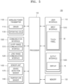
- FIG. 5 is a functional block diagram of the electronic device 100 according to an embodiment of the present disclosure.
- the electronic device 100 shown in FIG. 5 may be represented by an induction or a wireless power transmission device.
- the electronic device 100 may include the user interface 110, the processor 120, the memory 130, a wireless power transmitter 1100, the communication interface 1500 and the sensor unit 1400.
- the user interface 110 may include an input interface 1510 and an output interface 1520.
- the input interface 1510 may be configured for receiving inputs from the user.
- the input interface 1510 may include the touch panel 30 according to an embodiment of the present disclosure, but is not limited thereto.
- the input interface 1510 may be at least one of a key pad, a dome switch, a jog wheel, a jog switch or a microphone, but is not limited thereto.
- the microphone may be included even in the sensor unit 1400.
- the touch panel 30 may be configured in a capacitive method, as shown in FIG. 1 .
- the touch panel 30 may include at least one touch button 10, the capacitor C1 coupled with the touch button 10, and the switch 20 for charging or discharging the capacitor C1, but is not limited thereto.
- the switch 20 is turned on or off based on the frequencies spread by the processor 120 (a certain number of frequencies spread from the operating frequency in a certain range). Hence, the processor 120 may determine whether a touch input occurs on the touch button 10 by measuring the charging time t of the capacitor C1.
- the output interface 1520 is for outputting audio or video signals, and may include the display 70 and a sound output unit (e.g., a speaker).
- the output interface 1520 may display at least one piece of information indicating a power level, cooking time and/or menu check of the electronic device 100 on the display 70.
- the output interface 1520 may output at least one piece of information indicating a power level, cooking time and/or menu check of the electronic device 100 through the sound output unit (e.g., a speaker) in the form of notification sound or guidance sound.
- the display 70 may include at least one of a liquid crystal display (LCD), a thin film transistor-liquid crystal display (TFT-LCD), light emitting diodes (LEDs), organic LEDs (OLEDs), a flexible display, a three-dimensional (3D) display, or an electrophoretic display.
- the display 70 may display touch data (e.g., touch location information) corresponding to the touch input received through the touch button 10.
- touch data corresponding to the touch input on the touch button 10 may be displayed in real time.
- touch data e.g., information indicating a power level, a cooking time and/or menu check
- the displayed touch data may be mentioned as a result data, response data or feedback data of the electronic device 100 corresponding to the touch input on the touch button 10.
- the memory 130 may store a program (or instructions) for processing and controlling of the processor 120, and even store input/output data and data associated with the touch panel 30 (e.g., information about a certain frequency range and a certain number of frequencies, thresholds, the normal charging time t1 of the capacitor C1, or the like).
- An Al model (or a learning model) may be stored in the memory 130.
- the memory 130 may include at least one type of storage medium including a flash memory, a hard disk, a multimedia card micro type memory, a card type memory (e.g., SD or XD memory), a RAM, an SRAM, a ROM, an EEPROM, a PROM, a magnetic memory, a magnetic disk, and an optical disk. Furthermore, the electronic device 100 may operate a web storage or a cloud server that performs a storage function on the Internet.
- the wireless power transmitter 1100 may include a driver 1110 and an operating coil 1120, but is not limited thereto.
- the driver 1110 may receive power from an external power source and supply a current to the operating coil 1120 according to a driving control signal of the processor 120.
- the driver 1110 may include, but not limited to, an electromagnetic interference (EMI) filter, a rectifying circuit, an inverter circuit, a current detection circuit, and a driving processor.
- EMI electromagnetic interference
- the EMI filter may cut off high frequency noise contained in alternate current (AC) power supplied from the external source (ES), and pass an AC voltage and AC current with a preset frequency (e.g., 50 Hz or 60 Hz).
- the AC power from which high frequency noise is cut off by the EMI filter may be supplied to the rectifying circuit.
- the rectifying circuit may convert the supplied AC power to direct current (DC) power.
- the inverter circuit may include a switching circuit for supplying or blocking the driving current to the operating coil 1120.
- the switching circuit may be turned on or off by a driving control signal of the driving processor. By turning on or off the switching circuit, the magnitude and direction of the current flowing to the operating coil 1120 may be changed.
- a current detection circuit may include a current sensor for measuring a current output from the inverter circuit. An electric signal corresponding to the measured current value may be transmitted to the driving processor.
- the driving processor may generate a driving control signal to determine on or off of the switching circuit based on an output intensity (power level) of the electronic device 100.
- the operating coil 110 may produce a magnetic field for heating a cooking container (or cooking device). For example, when a driving current is supplied to the operating coil 1120, a magnetic field may be induced around the operating coil 1120. When a current that changes in magnitude and direction over time, i.e., an AC current, is supplied to the operating coil 1120, a magnetic field that changes in magnitude and direction over time may be induced around the operating coil 1120. The magnetic field around the operating coil 1120 may pass an upper plate formed of tempered glass, and reach the cooking container put on the upper plate. Due to the magnetic field changing in magnitude and direction over time, an eddy current that turns around the magnetic field may be generated to the cooking container. The eddy current may cause electrical resistance heat to the cooking container. The electrical resistance heat is produced to a resistor when a current flows in the resistor, and also referred to as Joule heat. The cooking container may be heated by the electrical resistance heat and contents in the cooking container may be heated.
- a current that changes in magnitude and direction over time i
- the processor 120 may control general operation of the electronic device 100.
- the processor 120 may execute programs stored in the memory 130 to control the wireless power transmitter 1100, the communication interface 1300, the sensor unit 1400, the user interface 110, and the memory 130.
- the processor 120 may be provided in the plural in some embodiments, and thus, may also referred to as at least one processor.
- the processor 120 may include a main processor and a subprocessor.
- the electronic device 100 may be equipped with an Al model based processor.
- the Al model based processor may be manufactured into the form of a dedicated hardware chip for Al, or manufactured as a portion of the existing universal processor (e.g., a CPU or an AP) or GPU and mounted in the electronic device 100.
- the communication interface 1500 may include one or more components that provide communication between the electronic device 100 and the cooking container or between the electronic device 100 and the server device 200 or communication between the electronic device 100 and the user equipment 300.
- the communication interface 1500 may include a short-range communication interface 1510 and/or a long-range communication interface 1520.
- the short-range communication interface 1510 may include at least one of a Bluetooth TM communication interface, a Bluetooth TM low energy (BLE) communication interface, a near field communication interface (NFC), a wireless local area network (WLAN), e.g., Wi-Fi, communication interface, a Zigbee communication interface, an infrared data association (IrDA) communication interface, a Wi-Fi direct (WFD) communication interface, an ultra wideband (UWB) communication interface, or an Ant+ communication interface, but is not limited thereto.
- a Bluetooth TM communication interface e.g., Wi-Fi, communication interface, a Zigbee communication interface, an infrared data association (IrDA) communication interface, a Wi-Fi direct (WFD) communication interface, an ultra wideband (UWB) communication interface, or an Ant+ communication interface, but is not limited thereto.
- BLE Bluetooth TM low energy
- NFC near field communication interface
- WLAN wireless local area network
- IrDA infrared data association
- the long-range communication interface 1520 may be used to communicate with the server device 200 or the user equipment 300 when the cooking container is controlled by the server device 200 or the user equipment 300 remotely in an loT environment.
- the long-range communication interface 1520 may include at least one of the Internet, a computer network (e.g., a local area network (LAN) or wide area network (WAN)), or a mobile communication unit.
- the mobile communication unit may transmit and receive wireless signals to and from at least one of a base station, an external terminal (e.g., the user equipment 300), or the server device 200 over a mobile communication network.
- the wireless signal may include a voice call signal, a video call signal or different types of data involved in transmission/reception of a text/multimedia message.
- the mobile communication unit may include at least one of a 3G module, a 4G module, an LTE module, a 5G module, a 6G module, an NB-loT module, or an LTE-M module, or the like, but is not limited thereto.
- the sensor unit 1400 may include at least one of a device detection sensor 1470 and a temperature sensor 1460, but is not limited thereto.
- the device detection sensor 1470 may be a sensor for detecting the cooking container being put on the upper plate.
- the device detection sensor 1470 may be implemented with a current sensor, but is not limited thereto.
- the device detection sensor 1470 may be implemented with at least one of a proximity sensor, a touch sensor, a weight sensor, a temperature sensor, a light sensor or a magnetic sensor.
- the temperature sensor 1460 may detect the temperature of the cooking container put on the upper plate or the temperature of the upper plate.
- the cooking container may be induction-heated by the operating coil, and may be overheated depending on the material.
- the electronic device 100 may detect the temperature of the cooking container put on the upper plate or the temperature of the upper plate, and terminate operation of the operating coil when the cooking container is overheated.
- the temperature sensor 1460 may include a thermistor whose electric resistance is changed according to the temperature.
- the temperature sensor 1460 may be a negative temperature coefficient (NTC) temperature sensor, but is not limited thereto.
- NTC negative temperature coefficient
- PTC positive temperature coefficient
- FIG. 6 is a flowchart of a method of operating the electronic device 100, according to an embodiment of the present disclosure.
- the electronic device 100 may spread an operating frequency into a certain number of frequencies within a certain frequency range.
- the electronic device 100 may spread the operating frequency (e.g., 150 kHz) into n (e.g., 16) frequencies within a frequency range of (the operating frequency ⁇ X (e.g., 10%) as shown in FIG. 3 .
- the electronic device 100 may spread a certain number of frequencies within a certain frequency range centered at the operating frequency of the switch 20. For example, the electronic device 100 may spread eight (8) frequencies between 135 kHz and 150 kHz and eight (8) frequencies between 150 kHz and 165 kHz centered at a fixed operating frequency 150 kHz, as shown in FIG. 3 .
- the electronic device 100 may spread the operating frequency into eight (8) frequencies (e.g., 135 kHz, 137 kHz, 139 kHz, 141 kHz, 143 kHz, 145 kHz, 147 kHz and 149 kHz), and another eight (8) frequencies (e.g., 151 kHz, 153 kHz, 155 kHz, 157 kHz, 159 kHz, 161 kHz, 163 kHz and 165 kHz), with gaps of 2 kHz.
- frequencies e.g., 135 kHz, 137 kHz, 139 kHz, 141 kHz, 143 kHz, 145 kHz, 147 kHz and 149 kHz
- another eight (8) frequencies e.g., 151 kHz, 153 kHz, 155 kHz, 157 kHz, 159 kHz, 161 kHz, 163 kHz and 165 kHz
- the electronic device 100 may control the switch 20 to be turned on or off based on the spread frequencies. For example, when the spread frequencies have 16 frequencies within a frequency range of the operating frequency (150 kHz) ⁇ 10%, the electronic device 100 may control the switch 20 to be turned on or off based on the spread 16 frequencies as shown in FIG. 3 .
- the controlling of the switch 20 to be turned on or off based on the spread frequencies may be described as controlling the switch 20 to be turned on or off by using a control signal based on the spread frequencies.
- the electronic device 100 may control the switch 20 to be turned on or off based on a frequency of 165 kHz. The electronic device 100 may then control the switch 20 to be turned on or off based on a frequency of 163 kHz.
- the eight (8) frequencies e.g., 135 kHz, 137 kHz, 139 kHz, 141 kHz, 143 kHz, 145 kHz, 147 kHz and 149kHz
- the electronic device 100 may control the switch 20 to be turned on or off based on a frequency of 165 kHz.
- the electronic device 100 may then control the switch 20 to be turned on or off based on a frequency of 163 kHz.
- the electronic device 100 may then control the switch 20 to be turned on or off based on a frequency of 161 kHz.
- the electronic device 100 may then control the switch 20 to be turned on or off based on a frequency of 159 kHz.
- the electronic device 100 may then control the switch 20 to be turned on or off based on a frequency of 157 kHz.
- the electronic device 100 may then control the switch 20 to be turned on or off based on a frequency of 155 kHz.
- the electronic device 100 may then control the switch 20 to be turned on or off based on a frequency of 153 kHz.
- the electronic device 100 may then control the switch 20 to be turned on or off based on a frequency of 151 kHz.
- the electronic device 100 may then control the switch 20 to be turned on or off based on a frequency of 149 kHz. The electronic device 100 may then control the switch 20 to be turned on or off based on a frequency of 147 kHz. The electronic device 100 may then control the switch 20 to be turned on or off based on a frequency of 145 kHz. The electronic device 100 may then control the switch 20 to be turned on or off based on a frequency of 143 kHz. The electronic device 100 may then control the switch 20 to be turned on or off based on a frequency of 141 kHz. The electronic device 100 may then control the switch 20 to be turned on or off based on a frequency of 139 kHz. The electronic device 100 may then control the switch 20 to be turned on or off based on a frequency of 137 kHz. The electronic device 100 may then control the switch 20 to be turned on or off based on a frequency of 135 kHz.
- the changing the spread frequencies is not limited to sequential changes in sequence as described above.
- the electronic device 100 may use one frequency multiple times to control the switch 20 to be turned on or off.
- the electronic device 100 may use a frequency of 165 kHz multiple times (e.g., three to eight times) to control the switch 20 to be turned on or off.
- the processor 120 may then use from 163 kHz to 135 kHz in sequence multiple times (e.g., three to eight times) to control the switch 20 to be turned on or off.
- the electronic device 100 may perform an operation to control the switch 20 to be turned on or off by switching frequencies from 135 kHz to 165 kHz in a reverse sequence to what is described above.
- the electronic device 100 may perform an operation to control the switch 20 to be turned on or off by sequentially switching frequencies from 135 kHz to 165 kHz in a reverse sequence to what is described above.
- the electronic device 100 may measure the charging time t of the capacitor C1.
- the measuring of the charging time t of the capacitor C1 may also be said as obtaining the charging time t of the capacitor C1.
- the electronic device 100 may measure the charging time t of the capacitor C1 each time to control the switch 20 to be turned on or off with the certain number of frequencies (e.g., 135 kHz, 137 kHz, 139 kHz, 141 kHz, 143 kHz, 145 kHz, 147 kHz, 149 kHz, 151 kHz, 153 kHz, 155 kHz, 157 kHz, 159 kHz, 161 kHz, 163 kHz and 165 kHz).
- frequencies e.g., 135 kHz, 137 kHz, 139 kHz, 141 kHz, 143 kHz, 145 kHz, 147 kHz, 149 kHz, 151 kHz, 153 k
- the number of charging times t of the capacitor C1 measured by the electronic device 100 may be 16.
- the electronic device 100 may measure 48 (16x3) charging times t of the capacitor C1, in operation S630.
- the electronic device 100 may determine whether a touch input occurs on the touch button 10 based on the measured charging time t of the capacitor C1. For example, the electronic device 100 may obtain an average value of the certain number of charging times t of the capacitor C1 measured by controlling the switch to be turned on or off based on the certain number of frequencies. For example, when the number of frequencies is 16, the charging time t of the capacitor C1 is measured 16 times, so the electronic device 100 may obtain an average value of the 16 measured charging times t of the capacitor C1.
- the electronic device 100 may use the obtained average value of the charging times (t) of the capacitor C1 to determine whether a touch input occurs on the touch button 10 as shown in FIG. 7 as will be described later.
- the electronic device 100 may determine whether a touch input occurs on the touch button 10 by using the charging time t of the capacitor C1 measured while controlling the switch 20 to be turned on or off for each of the spread frequencies. For example, the electronic device 100 may determine whether a touch input occurs on the touch button 10 by using on the charging time t of the capacitor C1 measured based on a frequency of 165 kHz. The electronic device 100 may use the charging time t of the capacitor C1 measured based on the next frequency (e.g., 163 kHz) to determine whether a touch input occurs on the touch button 10.
- the next frequency e.g. 163 kHz
- the electronic device 100 may make a final decision about whether a touch input occurs on the touch button 10 based on a result of determining based on the 16 frequencies (a result of determining whether a touch input occurs), an operation of determining whether a touch input occurs on the touch button 10 based on the charging time t of the capacitor C1 according to an embodiment of the present disclosure is not limited thereto.
- FIG. 7 is a flowchart of a procedure for determining whether a touch input occurs on the touch button 10 in a method of operating the electronic device 100, according to an embodiment of the present disclosure.
- the electronic device 100 compares the obtained first difference value d1 with a threshold value.
- the electronic device 100 may determine that a touch input occurs on the touch button 10 based on the obtained first difference value d1 exceeds the threshold value.
- the electronic device 100 may determine that no touch input occurs on the touch button 10.
- FIG. 8 is a flowchart of operation of the electronic device 100, according to an embodiment of the present disclosure.
- FIG. 8 is an example including an operation of reading information about a certain number of frequencies within a certain frequency range from the memory, in addition to the flowchart of FIG. 6 .
- the electronic device 100 may read information about a certain number of frequencies within a certain frequency range stored in the memory 130.
- the electronic device 100 may spread an operating frequency into a preset number of frequencies within a preset frequency range.
- the electronic device 100 may spread the operating frequency (e.g., 150 kHz) as shown in FIG. 3 into n (e.g., 16) frequencies within a frequency range of the operating frequency ⁇ X (e.g., 10)%.
- the electronic device 100 may spread an operating frequency of the switch 20 into a certain number of frequencies within a certain frequency range centered at the operating frequency. For example, the electronic device 100 may spread 8 frequencies between 135 kHz to 150 kHz and eight (8) frequencies between 150 kHz to 165 kHz based on a fixed operating frequency of 150 kHz, as shown in FIG. 3 .
- the electronic device 100 may spread the operating frequency into eight (8) frequencies (e.g., 135 kHz, 137 kHz, 139 kHz, 141 kHz, 143 kHz, 145 kHz, 147 kHz and 149 kHz), and another eight 8 frequencies (e.g., 151 kHz, 153 kHz, 155 kHz, 157 kHz, 159 kHz, 161 kHz, 163 kHz and 165 kHz), with gaps of 2 kHz.
- frequencies e.g., 135 kHz, 137 kHz, 139 kHz, 141 kHz, 143 kHz, 145 kHz, 147 kHz and 149 kHz
- another eight 8 frequencies e.g., 151 kHz, 153 kHz, 155 kHz, 157 kHz, 159 kHz, 161 kHz, 163 kHz and 165 kHz
- the electronic device 100 may control the switch 20 to be turned on or off based on the spread frequencies. For example, when the spread frequencies have 16 frequencies within a frequency range of the operating frequency (150 kHz) ⁇ 10%, the electronic device 100 may control the switch 20 to be turned on or off based on the spread 16 frequencies as shown in FIG. 3 .
- the electronic device 100 may control the switch 20 to be turned on or off based on a frequency of 165 kHz. The electronic device 100 may then control the switch 20 to be turned on or off based on a frequency of 163 kHz.
- the eight (8) frequencies e.g., 135 kHz, 137 kHz, 139 kHz, 141 kHz, 143 kHz, 145 kHz, 147 kHz and 149kHz
- the electronic device 100 may control the switch 20 to be turned on or off based on a frequency of 165 kHz.
- the electronic device 100 may then control the switch 20 to be turned on or off based on a frequency of 163 kHz.
- the electronic device 100 may then control the switch 20 to be turned on or off based on a frequency of 161 kHz.
- the electronic device 100 may then control the switch 20 to be turned on or off based on a frequency of 159 kHz.
- the electronic device 100 may then control the switch 20 to be turned on or off based on a frequency of 157 kHz.
- the electronic device 100 may then control the switch 20 to be turned on or off based on a frequency of 155 kHz.
- the electronic device 100 may then control the switch 20 to be turned on or off based on a frequency of 153 kHz.
- the electronic device 100 may then control the switch 20 to be turned on or off based on a frequency of 151 kHz.
- the electronic device 100 may then control the switch 20 to be turned on or off based on a frequency of 149 kHz. The electronic device 100 may then control the switch 20 to be turned on or off based on a frequency of 147 kHz. The electronic device 100 may then control the switch 20 to be turned on or off based on a frequency of 145 kHz. The electronic device 100 may then control the switch 20 to be turned on or off based on a frequency of 143 kHz. The electronic device 100 may then control the switch 20 to be turned on or off based on a frequency of 141 kHz. The electronic device 100 may then control the switch 20 to be turned on or off based on a frequency of 139 kHz. The electronic device 100 may then control the switch 20 to be turned on or off based on a frequency of 137 kHz. The electronic device 100 may then control the switch 20 to be turned on or off based on a frequency of 135 kHz.
- the switching between the spread frequencies is not limited to sequential switching as described above.
- the electronic device 100 may use one frequency multiple times to control the switch 20 to be turned on or off.
- the electronic device 100 may use the frequency of 165 kHz multiple times (e.g., three to eight times) to control the switch 20 to be turned on or off.
- the electronic device 100 may sequentially use the subsequent frequencies from 163 kHz to 135 kHz multiple times to control the switch 20 to be turned on or off.
- the electronic device 100 may control the switch 20 to be turned on or off by switching frequencies from 135 kHz to 165 kHz in a reverse sequence to what is described above.
- the electronic device 100 may control the switch 20 to be turned on or off by sequentially switching frequencies from 135 kHz to 165 kHz in a reverse sequence to what is described above.
- the electronic device 100 may measure the charging time t of the capacitor C1.
- the measuring of the charging time t of the capacitor C1 may also be said as obtaining the charging time t1 of the capacitor C1.
- the electronic device 100 may measure the charging time t of the capacitor C1 each time to control the switch 20 to be turned on or off with the certain number of frequencies (e.g., 135 kHz, 137 kHz, 139 kHz, 141 kHz, 143 kHz, 145 kHz, 147 kHz, 149 kHz, 151 kHz, 153 kHz, 155 kHz, 157 kHz, 159 kHz, 161 kHz, 163 kHz and 165 kHz).
- frequencies e.g., 135 kHz, 137 kHz, 139 kHz, 141 kHz, 143 kHz, 145 kHz, 147 kHz, 149 kHz, 151 kHz, 153
- the number of charging times t of the capacitor C1 measured by the electronic device 100 may be 16.
- the electronic device 100 may measure 48 (16x3) charging times t of the capacitor C1, in operation S630.
- the electronic device 100 may determine whether a touch input occurs on the touch button 10 based on the measured charging time t of the capacitor C1. For example, the electronic device 100 may obtain an average value of the certain number of charging times t of the capacitor C1 measured by controlling the switch to be turned on or off by using the certain number of frequencies. For example, when the number of frequencies is 16, the charging time t of the capacitor C1 is measured 16 times, so the electronic device 100 may obtain an average value of the 16 measured charging times t of the capacitor C1.
- the electronic device 100 may use the obtained average value of the charging times (t) of the capacitor C1 to determine whether a touch input occurs on the touch button 10 as shown in FIG. 7 .
- the electronic device 100 may determine whether a touch input occurs on the touch button 10 by using the charging time t of the capacitor C1 measured by controlling the switch 20 to be turned on or off for each of the spread frequencies. For example, the electronic device 100 may determine whether a touch input occurs on the touch button 10 by using the charging time t of the capacitor C1 measured based on a frequency of 165 kHz. The electronic device 100 may use the charging time t of the capacitor C1 measured based on the next frequency (e.g., 163 kHz) to determine whether a touch input occurs on the touch button 10.
- the next frequency e.g. 163 kHz
- the electronic device 100 may make a final decision on whether a touch input occurs on the touch button 10 based on a result of determining based on the 16 frequencies (a result of determining whether a touch input occurs), an operation of determining whether a touch input occurs on the touch button 10 based on the charging time t of the capacitor C1 according to an embodiment of the present disclosure is not limited thereto.
- FIGS. 6 to 8 as described above may be performed by the processor 120 of the electronic device 100.
- FIG. 9 is a diagram of operations associated with the electronic device 100, the server device 200 and the user equipment 300, according to an embodiment of the present disclosure.
- the electronic device 100 may communicate with the server device 200 and the user equipment 300.
- the electronic device 100 may transmit identity information of the electronic device 100 or identity information of the user (e.g., login information or account information) to the server device 200.
- the server device 200 may authenticate the electronic device 100 based on the received identity information of the electronic device 100 or the identity information of the user (e.g., login information or account information), transmit the authentication result to the electronic device 100, and then allow the server device 200 to access the electronic device 100.
- the electronic device 100 may request the server device 200 to update software related to the electronic device 100 as the access from the server device 200 is allowed.
- the software related to the electronic device 100 may include software for determining whether a touch input occurs on the touch button 10.
- the information about a certain frequency range and the certain number of frequencies for controlling the switch 20 to be turned on or off included in the software for determining whether a touch input occurs on the touch button 10 may be the same as or different from information about the certain frequency range and the certain number of frequencies for controlling the switch 20 to be turned on or off included in the software stored in the electronic device 100.
- the server device 200 may include a communication interface for communicating with an external device.
- the server device 200 may communicate with the electronic device 100 or the user equipment 300 through the communication interface.
- the server device 200 may update the software of the electronic device 100 based on the communicating with the electronic device 100 or transmit updated software related to the electronic device 100 based on the communicating with the user equipment 300.
- the server device 200 may include an Al processor.
- the Al processor may input information into an Al model for the touch button 10 of the electronic device 100 for training. This information may include an amount of noise likely to be introduced to the electronic device 100, the charging time t of the capacitor C1 measured according to the turning on or off of the switch 20 based on the certain number of frequencies within the certain operating frequency range, and speed of operation for determining whether a touch input occurs on the touch button 10 of the processor 120.
- the training of the Al model may refer to building a mathematical model that is able to make a best decision while changing weights properly based on the input data.
- the user equipment 300 may be connected to the server device 200 and may wirelessly (or remotely) control an operation of the electronic device 100 or update the software of the electronic device 100 based on a program provided from the server device 200.
- the user equipment 300 may transmit or receive information to or from the server device 200 through a certain application (a management application for the electronic device 100) installed in the user equipment 300.
- the user equipment 300 may be connected to the server device 200 by using the identity information of the user (e.g., the login information or account information) that is equal to the electronic device 100.
- the user equipment 300 may be directly connected to the electronic device 100 through a short-range wireless communication channel or indirectly connected to the electronic device 100 through the server device 200.
- the user equipment 300 may be implemented in various forms.
- the user equipment 300 as described herein may be a mobile terminal, a vehicle, a refrigerator with a display, a television (TV), a computer, or the like, but is not limited thereto.
- the mobile terminal may include a smart phone, a laptop computer, a tablet personal computer (tablet PC), a digital camera, an electronic book (e-book) reader, a digital broadcasting terminal, a personal digital assistant (PDA), a portable multimedia player (PMP), a navigation system, an MP3 player, or the like, but is not limited thereto.
- the mobile terminal may be a wearable device that may be worn by the user.
- the user equipment 300 or the electronic device 100 may receive an analog voice signal through a microphone, and convert a voice part into computer-readable text by using an automatic speech recognition (ASR) model.
- the user equipment 300 or the electronic device 100 may obtain the user's intention of talking by interpreting the converted text by using a natural language understanding (NLU) model.
- the ASR model or the NLU model may be an Al model.
- the Al model may be processed by an Al dedicated processor designed in a hardware structure specialized in processing the Al model.
- the Al model may be made by learning.
- the learning may be performed in a device itself where the Al according to the present disclosure is performed (e.g., the user equipment 300 or the electronic device 100) or performed through a separate server device 200 and/or a system. Examples of the learning algorithm may include supervised learning, unsupervised learning, semi-supervised learning, or reinforcement learning, but is not limited thereto.
- the user equipment 300 may run a certain application (e.g., a management application for the electronic device 100) provided by the server device 200, based on a user input.
- a management application for the electronic device 100 e.g., a management application for the electronic device 100
- the user may control an operation of the electronic device 100 through the application's running screen and check a monitoring image or a cooking process image in the inside space (e.g., a cooking chamber) of the electronic device 100.
- the electronic device 100 including the user interface 110 and the at least one processor 120, wherein the user interface 110 may include the at least one touch button 10, the capacitor C1 coupled with the at least one touch button 10, and the switch 20 coupled between the at least one touch button 10 and the capacitor C1 and configured to charge or discharge the capacitor C1, and the at least one processor 120 may spread an operating frequency into a certain number of frequencies within a certain frequency range, control the switch 20 to be turned on or off based on the spread frequencies, measure the charging time t of the capacitor C1 according to the turning on or off of the switch 20, and determine whether a touch input occurs on the touch button 10 based on the measured charging time t. Accordingly, the electronic device 100 may prevent wrong decision of a touch input due to noise.
- the electronic device 100 includes the user interface 110 for receiving a user input through the at least one touch button 10, and at least one processor 120, wherein the at least one processor 120 may spread an operating frequency into a certain number of frequencies within a certain frequency range, control the switch 20 to be turned on or off to charge or discharge the capacitor C1 coupled with the at least one touch button 10 based on the spread frequencies, measure the charging time t of the capacitor C1 according to the turning on or off of the switch 20, and determine whether a touch input occurs on the touch button 10 based on the measured charging time t.
- the at least one processor 120 may obtain the first difference value d1 between the measured charging time t of the capacitor C1 and the normal charging time t1 of the capacitor C1 based onthe touch input on the touch button 10 has not occurred, determine that the touch input on the touch button 10 has occurred based on the obtained first difference value d1 exceeding a threshold value, and determine that the touch input on the touch button 10 has occurred based on the obtained first difference value d1 being less than or equal to the threshold value.
- the threshold value may be the second difference value d2 between the charging time t2 of the capacitor C1 based on a normal touch input on the touch button 10 has occurred and the normal charging time t1 of the capacitor C1 while no touch input occurs on the touch button 10.
- the measured charging time t of the capacitor C1 may be an average value of a certain number of charging times of the capacitor C1, which are obtained according to turning on or off of the switch 20 based on a certain number of frequencies.
- the at least one processor 120 may control the switch 20 to be turned on or off by switching between the spread frequencies.
- the at least one processor 120 may control the switch 20 to be turned on or off by sequentially switching the spread frequencies.
- the at least one processor 120 may use the same frequency multiple times to control the switch 20 to be turned on or off based on the spread frequencies.
- the electronic device 100 may include the memory 130 for storing information about a certain number of spread frequencies within a certain frequency range, and the at least one processor 120 may be configured to read out the information about the certain number of spread frequencies within the certain frequency range stored in the memory 130 to spread an operating frequency.
- the certain number of spread frequencies within the certain frequency range may be based on specifications of the electronic device 100.
- the certain number of spread frequencies within the certain frequency range may be based on at least one of an amount of noise likely to be introduced to the electronic device 100 and a speed of operation of the at least one processor 120 determining whether a touch input occurs on the touch button 10.
- the at least one processor 120 may include spreading an operating frequency into a certain number of frequencies within a certain frequency range, controlling the switch 20 to be turned on or off to charge or discharge the capacitor C1 based on the spread frequencies, measuring the charging time t of the capacitor C1 according to the turning on or off of the switch 20, and determining whether a touch input occurs on the touch button 10 based on the measured charging time t.
- the determining of whether a touch input occurs on the touch button 10 may include obtaining the first difference value d1 between the measured charging time t of the capacitor C1 and the normal charging time t1 of the capacitor C1 based on the touch input occurs on the touch button 10 has occurred, determining that the touch input on the touch button 10 hae occurred based on the obtained first difference value d1 exceeding a threshold value, and determining that the touch input on the touch button 10 has not occurred based on the obtained first difference value d1 being less than or equal to the threshold value.
- the controlling of the switch 20 to be turned on or off may be performed by switching between the spread frequencies.
- the controlling of the switch 20 to be turned on or off may be performed by sequentially switching the spread frequencies.
- the controlling of the switch 20 to be turned on or off based on the spread frequencies may include controlling the switch 20 to be turned on or off by using the same frequency multiple times.
- the method may include reading information about a certain number of frequencies spread within a certain frequency range from the memory 130 included in the electronic device 100.
- the machine-readable storage medium may be provided in the form of a non-transitory storage medium.
- the term 'non-transitory storage medium' may mean a tangible device without including a signal (e.g., electromagnetic waves), and may not distinguish between storing data in the storage medium semi-permanently and temporarily.
- the non-transitory storage medium may include a buffer that temporarily stores data.
- the aforementioned method according to the various embodiments of the present disclosure may be provided in a computer program product.
- the computer program product may be a commercial product that may be traded between a seller and a buyer.
- the computer program product may be distributed in the form of a machine-readable storage medium (e.g., a CD-ROM) or distributed directly between two user devices (e.g., smart phones) or online (e.g., downloaded or uploaded).
- a machine-readable storage medium e.g., a CD-ROM
- two user devices e.g., smart phones
- online e.g., downloaded or uploaded
- at least part of the computer program product e.g., a downloadable app
Landscapes
- Engineering & Computer Science (AREA)
- General Engineering & Computer Science (AREA)
- Theoretical Computer Science (AREA)
- Human Computer Interaction (AREA)
- Physics & Mathematics (AREA)
- General Physics & Mathematics (AREA)
- Electronic Switches (AREA)
Applications Claiming Priority (3)
| Application Number | Priority Date | Filing Date | Title |
|---|---|---|---|
| KR20220118163 | 2022-09-19 | ||
| KR1020230013189A KR20240039576A (ko) | 2022-09-19 | 2023-01-31 | 터치 입력 오결정을 방지할 수 있는 전자 장치 및 그의 동작 방법 |
| PCT/KR2023/011609 WO2024063329A1 (fr) | 2022-09-19 | 2023-08-07 | Dispositif électronique pour améliorer la sensibilité d'entrée tactile et procédé de fonctionnement associé |
Publications (2)
| Publication Number | Publication Date |
|---|---|
| EP4553626A1 true EP4553626A1 (fr) | 2025-05-14 |
| EP4553626A4 EP4553626A4 (fr) | 2025-10-22 |
Family
ID=90454609
Family Applications (1)
| Application Number | Title | Priority Date | Filing Date |
|---|---|---|---|
| EP23868389.0A Pending EP4553626A4 (fr) | 2022-09-19 | 2023-08-07 | Dispositif électronique pour améliorer la sensibilité d'entrée tactile et procédé de fonctionnement associé |
Country Status (3)
| Country | Link |
|---|---|
| US (1) | US12510997B2 (fr) |
| EP (1) | EP4553626A4 (fr) |
| WO (1) | WO2024063329A1 (fr) |
Family Cites Families (33)
| Publication number | Priority date | Publication date | Assignee | Title |
|---|---|---|---|---|
| US6819011B2 (en) | 2002-11-14 | 2004-11-16 | Fyre Storm, Inc. | Switching power converter controller with watchdog timer |
| KR100469355B1 (ko) | 2002-11-14 | 2005-02-02 | 엘지.필립스 엘시디 주식회사 | 표시장치용 터치 패널 |
| KR101163602B1 (ko) | 2005-08-18 | 2012-07-06 | 엘지디스플레이 주식회사 | 디스플레이 장치 및 그의 구동 방법 |
| KR101106655B1 (ko) | 2009-01-12 | 2012-01-18 | (주)미래디피 | 정전용량 방식 터치 패널 |
| KR101031996B1 (ko) | 2009-03-03 | 2011-05-02 | 주식회사 켐트로닉스 | 선형으로 변화되는 주파수를 이용한 터치 감지 장치 및 방법 |
| KR101135358B1 (ko) | 2009-03-03 | 2012-04-16 | 주식회사 켐트로닉스 | 노이즈 제거가 가능한 터치 감지 장치 및 방법 |
| JP4727754B1 (ja) * | 2010-03-04 | 2011-07-20 | Smk株式会社 | 静電容量式タッチパネル |
| KR101108703B1 (ko) * | 2010-03-18 | 2012-01-30 | 주식회사 지니틱스 | 터치스크린 장치, 터치패널의 구동장치 및 구동방법 |
| CN101976147B (zh) | 2010-09-30 | 2013-03-27 | 江苏惠通集团有限责任公司 | 触摸识别方法、触摸键结构及触摸装置 |
| KR101808339B1 (ko) | 2010-11-19 | 2017-12-13 | 엘지디스플레이 주식회사 | 터치 스크린과 그 구동방법, 및 그 터치 스크린 패널을 포함한 표시장치 |
| KR101763939B1 (ko) | 2010-12-08 | 2017-08-01 | 엘지디스플레이 주식회사 | 터치스크린 패널 일체형 표시장치와 그의 노이즈 보상방법 |
| KR101773612B1 (ko) | 2011-01-13 | 2017-08-31 | 삼성전자주식회사 | 터치 영역 확인 장치 및 방법 |
| KR101771078B1 (ko) | 2011-01-17 | 2017-09-05 | 엘지디스플레이 주식회사 | 터치 감지 회로 및 이를 포함하는 디스플레이 장치 |
| KR101756668B1 (ko) * | 2011-06-01 | 2017-07-26 | 엘지디스플레이 주식회사 | 터치표시장치 및 터치판단방법 |
| KR101848274B1 (ko) | 2011-09-29 | 2018-04-13 | 주식회사 지2터치 | 드라이빙 백 현상을 이용한 터치 검출수단, 검출방법 및 터치스크린패널과, 그러한 터치스크린패널을 내장한 표시장치 |
| JP5919767B2 (ja) * | 2011-11-30 | 2016-05-18 | ぺんてる株式会社 | 静電容量結合方式静電センサー |
| KR101340026B1 (ko) | 2012-02-08 | 2013-12-10 | (주)이엔에이치 | 정전용량 방식의 터치스크린 패널 및 그 제조방법 |
| KR101871667B1 (ko) | 2012-03-16 | 2018-06-27 | 엘지디스플레이 주식회사 | 터치스크린 연결용 연성인쇄회로기판 및 이를 이용한 액정표시장치 |
| US9411928B2 (en) * | 2012-07-17 | 2016-08-09 | Parade Technologies, Ltd. | Discontinuous integration using half periods |
| KR101282915B1 (ko) * | 2013-04-25 | 2013-07-17 | 주식회사 아나패스 | 노이즈 영향 감소 방법 및 이를 이용한 터치 검출 장치 |
| KR101501126B1 (ko) * | 2013-05-29 | 2015-03-11 | 영남대학교 산학협력단 | 정전 용량 측정 방법 및 이를 이용한 정전용량센서 |
| KR101497405B1 (ko) | 2013-08-07 | 2015-03-04 | 주식회사 하이딥 | 터치패널 입력장치 및 그의 입력검출방법 |
| KR101606404B1 (ko) | 2014-03-05 | 2016-03-25 | 주식회사 동부하이텍 | 터치 센서 |
| KR20150134484A (ko) | 2014-05-21 | 2015-12-02 | 삼성디스플레이 주식회사 | 무선 통신 장치 및 무선 통신 장치에 포함되는 디스플레이 장치의 구동 방법 |
| KR102298488B1 (ko) | 2014-12-30 | 2021-09-08 | 엘지디스플레이 주식회사 | 터치 센서들을 가지는 표시장치와 그 게이트 구동 회로 |
| KR101566939B1 (ko) | 2015-03-05 | 2015-11-06 | 주식회사 지2터치 | 정전식 터치 신호 검출 장치 및 방법 |
| KR101602842B1 (ko) | 2015-03-05 | 2016-03-11 | 주식회사 지2터치 | 정전식 터치 신호 검출 장치 및 방법 |
| KR20170003041A (ko) * | 2015-06-30 | 2017-01-09 | 삼성전자주식회사 | 유효한 유저 입력을 판단하는 전자 장치 |
| KR102430780B1 (ko) | 2017-09-08 | 2022-08-09 | 엘지디스플레이 주식회사 | 터치 디스플레이 장치, 터치 회로 및 터치 센싱 방법 |
| CN109471566B (zh) | 2017-09-08 | 2022-03-29 | 乐金显示有限公司 | 触摸显示装置、触摸电路和触摸感测方法 |
| CN109039319B (zh) * | 2018-08-13 | 2022-05-31 | 中科芯集成电路有限公司 | 一种抗干扰的电容式触摸按键控制器及实现方法 |
| US11456740B2 (en) * | 2020-07-16 | 2022-09-27 | Pixart Imaging Inc. | Touch detection circuit with different charging and discharging currents and operating method thereof |
| TWI828392B (zh) * | 2022-10-27 | 2024-01-01 | 新唐科技股份有限公司 | 觸控感測電路及觸控判斷方法 |
-
2023
- 2023-08-07 EP EP23868389.0A patent/EP4553626A4/fr active Pending
- 2023-08-07 WO PCT/KR2023/011609 patent/WO2024063329A1/fr not_active Ceased
-
2025
- 2025-01-17 US US19/028,359 patent/US12510997B2/en active Active
Also Published As
| Publication number | Publication date |
|---|---|
| US12510997B2 (en) | 2025-12-30 |
| WO2024063329A1 (fr) | 2024-03-28 |
| US20250165103A1 (en) | 2025-05-22 |
| EP4553626A4 (fr) | 2025-10-22 |
Similar Documents
| Publication | Publication Date | Title |
|---|---|---|
| US11644198B2 (en) | Terminal, cooking appliance communicating therewith and method of controlling cooking appliance | |
| CN111770662B (zh) | 电子装置和用于控制电子装置的风扇的方法 | |
| EP3192182B1 (fr) | Dispositif électronique et procédé de détection de prise | |
| KR102625690B1 (ko) | 전력 전송 방법 및 이를 지원하는 전자 장치 | |
| US20180166922A1 (en) | Electronic device for receiving power wirelessly and method for controlling the electronic device | |
| KR102590943B1 (ko) | 전력 전송 장치 및 전력 전송 방법 | |
| CN112230611A (zh) | 智能家居设备的控制方法、装置、电子设备及存储介质 | |
| CN107407951B (zh) | 电子设备及其电池信息提供方法 | |
| CN107431389B (zh) | 驱动无动力传感器的电子设备和控制其的方法 | |
| US20220347862A1 (en) | Method and system for controlling cleaning robot | |
| JP6014568B2 (ja) | 制御装置、制御方法、制御システム、制御プログラム、および報知機器 | |
| KR20170030424A (ko) | 무선 전력 전송 방법 및 장치 | |
| US20180049293A1 (en) | Presence request via light adjustment | |
| CN109412913A (zh) | 智能家居设备的控制方法、装置、存储介质及终端 | |
| CN111245047B (zh) | 一种电磁装置的控制方法、电磁装置及存储介质 | |
| US11073944B2 (en) | Cooking apparatus and controlling method thereof | |
| EP3172638B1 (fr) | Procédé de commande de l'écran d'un dispositif électronique, et dispositif électronique correspondant | |
| EP4553626A1 (fr) | Dispositif électronique pour améliorer la sensibilité d'entrée tactile et procédé de fonctionnement associé | |
| CN106019958A (zh) | 手势识别控制方法、手势识别控制装置和设备 | |
| KR20220150131A (ko) | 청소 로봇을 제어하는 방법 및 시스템 | |
| KR20240039576A (ko) | 터치 입력 오결정을 방지할 수 있는 전자 장치 및 그의 동작 방법 | |
| KR102319981B1 (ko) | 다중 에너지 자원을 이용한 충전 방법 및 장치 | |
| CN103954020B (zh) | 空调器、空调器系统及空调器的控制方法 | |
| JP2016220257A (ja) | 制御装置、制御方法、制御システム、制御プログラム、および報知機器 | |
| US20250193505A1 (en) | Oven with adjustable brightness and oven operation method thereof |
Legal Events
| Date | Code | Title | Description |
|---|---|---|---|
| STAA | Information on the status of an ep patent application or granted ep patent |
Free format text: STATUS: THE INTERNATIONAL PUBLICATION HAS BEEN MADE |
|
| PUAI | Public reference made under article 153(3) epc to a published international application that has entered the european phase |
Free format text: ORIGINAL CODE: 0009012 |
|
| STAA | Information on the status of an ep patent application or granted ep patent |
Free format text: STATUS: REQUEST FOR EXAMINATION WAS MADE |
|
| 17P | Request for examination filed |
Effective date: 20250210 |
|
| AK | Designated contracting states |
Kind code of ref document: A1 Designated state(s): AL AT BE BG CH CY CZ DE DK EE ES FI FR GB GR HR HU IE IS IT LI LT LU LV MC ME MK MT NL NO PL PT RO RS SE SI SK SM TR |
|
| A4 | Supplementary search report drawn up and despatched |
Effective date: 20250919 |
|
| RIC1 | Information provided on ipc code assigned before grant |
Ipc: G06F 3/041 20060101AFI20250915BHEP Ipc: G06F 3/044 20060101ALI20250915BHEP Ipc: H03K 17/96 20060101ALI20250915BHEP |
|
| DAV | Request for validation of the european patent (deleted) | ||
| DAX | Request for extension of the european patent (deleted) |