EP4553776A1 - Bilddarstellungsverfahren, -vorrichtung und -einrichtung - Google Patents
Bilddarstellungsverfahren, -vorrichtung und -einrichtung Download PDFInfo
- Publication number
- EP4553776A1 EP4553776A1 EP23851213.1A EP23851213A EP4553776A1 EP 4553776 A1 EP4553776 A1 EP 4553776A1 EP 23851213 A EP23851213 A EP 23851213A EP 4553776 A1 EP4553776 A1 EP 4553776A1
- Authority
- EP
- European Patent Office
- Prior art keywords
- node
- view
- moment
- rendered
- field
- Prior art date
- Legal status (The legal status is an assumption and is not a legal conclusion. Google has not performed a legal analysis and makes no representation as to the accuracy of the status listed.)
- Pending
Links
Images



Classifications
-
- G—PHYSICS
- G06—COMPUTING OR CALCULATING; COUNTING
- G06T—IMAGE DATA PROCESSING OR GENERATION, IN GENERAL
- G06T15/00—Three-dimensional [3D] image rendering
- G06T15/10—Geometric effects
- G06T15/30—Clipping
-
- G—PHYSICS
- G06—COMPUTING OR CALCULATING; COUNTING
- G06V—IMAGE OR VIDEO RECOGNITION OR UNDERSTANDING
- G06V10/00—Arrangements for image or video recognition or understanding
- G06V10/70—Arrangements for image or video recognition or understanding using pattern recognition or machine learning
- G06V10/762—Arrangements for image or video recognition or understanding using pattern recognition or machine learning using clustering, e.g. of similar faces in social networks
- G06V10/7635—Arrangements for image or video recognition or understanding using pattern recognition or machine learning using clustering, e.g. of similar faces in social networks based on graphs, e.g. graph cuts or spectral clustering
-
- G—PHYSICS
- G06—COMPUTING OR CALCULATING; COUNTING
- G06T—IMAGE DATA PROCESSING OR GENERATION, IN GENERAL
- G06T15/00—Three-dimensional [3D] image rendering
-
- G—PHYSICS
- G06—COMPUTING OR CALCULATING; COUNTING
- G06T—IMAGE DATA PROCESSING OR GENERATION, IN GENERAL
- G06T15/00—Three-dimensional [3D] image rendering
- G06T15/005—General purpose rendering architectures
Definitions
- This application relates to the field of image processing technologies, and in particular, to an image rendering method, apparatus, and device.
- a rendering technology is one of important research topics in three-dimensional computer graphics.
- three-dimensional scene data and environment data are output, through calculation, as an image that simulates a real world.
- a rasterization rendering pipeline is one of mainstream rendering technologies.
- culling needs to be first performed at a granularity of an object, to exclude an object that is not displayed in a field of view; and in a rendering process, node clipping is performed at a granularity of a patch of the object, to remove a patch that is not displayed in the field of view.
- clipping in the rendering process is applicable to a single field of view, and in the rendering process, clipping of a to-be-rendered object in only one field of view at a granularity of a patch can be processed at one time.
- One clipping operation needs to be performed in each field of view, to obtain rendered images in a plurality of fields of view. Such a processing manner is inapplicable to a multi-field of view scenario in which there is a high latency requirement.
- This application provides an image rendering method, apparatus, and device, to implement image rendering in a plurality of fields of view.
- the DAG corresponding to the object describes an association relationship between clusters at the plurality of levels of the object, and one node in the DAG corresponding to the object represents one cluster at one level of the object.
- the rendering apparatus may perform node clipping on the node in the DAG corresponding to each object, to generate a to-be-rendered node list corresponding to the first moment, and render a cluster included in the to-be-rendered node list corresponding to the first moment, to obtain rendered images at the first moment in the plurality of fields of view.
- the rendering apparatus can synchronously process objects that need to be displayed in the plurality of fields of view at a same moment, to obtain rendered images at the same moment in the plurality of fields of view, implementing image rendering in the plurality of fields of view can be implemented, and effectively improving image rendering efficiency.
- the to-be-rendered node list corresponding to the first moment includes a plurality of nodes, and the plurality of nodes are grouped from a perspective of the field of view.
- the plurality of nodes may be divided into a plurality of groups, and each group corresponds to one field of view.
- a node in each group meets the following conditions:
- the to-be-rendered node list when the to-be-rendered node list is obtained, not only a relationship between the screen space error of the node at the first moment and the error threshold of the field of view is considered, but also a relationship between the screen space error of the parent node of the node at the first moment and the error threshold of the field of view is considered, so that the rendering apparatus can efficiently and flexibly implement node clipping.
- the to-be-rendered node list includes a cluster that needs to be rendered in each field of view, to ensure that the rendered images at the first moment in the plurality of fields of view can be obtained subsequently based on the cluster included in the to-be-rendered node list, and further ensure that image rendering in the plurality of fields of view can be implemented.
- the rendering apparatus may further generate a to-be-deleted node list corresponding to the first moment. Similar to the to-be-rendered node list corresponding to the first moment, the to-be-deleted node list corresponding to the first moment includes a plurality of nodes, and the plurality of nodes may be divided into a plurality of groups from a perspective of the field of view. Each group corresponds to one field of view.
- a node in each group meets the following conditions:
- the rendering apparatus when the to-be-deleted node list is obtained, not only a relationship between the screen space error of the node at the first moment and the error threshold of the field of view is considered, but also a relationship between the screen space error of the parent node of the node at the first moment and the error threshold of the field of view is considered, so that the rendering apparatus can efficiently and flexibly implement node clipping.
- the rendering apparatus may generate a to-be-rendered node list corresponding to a next moment based on a to-be-rendered node list and a to-be-deleted node list that correspond to an earlier moment, and render a cluster included in the to-be-rendered node list corresponding to the next moment, to obtain rendered images in the plurality of fields of view at a next moment.
- a next moment of the first moment is a second moment.
- the rendering apparatus may generate a to-be-rendered node list corresponding to the second moment based on the to-be-rendered node list and the to-be-deleted node list that correspond to the first moment.
- the rendering apparatus may render a cluster represented by a node in the to-be-rendered node list corresponding to the second moment, to obtain rendered images at the second moment in the plurality of fields of view.
- the rendering apparatus generates the to-be-rendered node list corresponding to the next moment based on the to-be-rendered node list and the to-be-deleted node list that correspond to the earlier moment, to further obtain the rendered images in the plurality of fields of view at the next moment efficiently and quickly.
- nodes included in the to-be-rendered node list corresponding to the second moment are divided into a plurality of groups, and each group corresponds to one field of view; and a node in each group meets the following conditions:
- the rendering apparatus may separately perform view frustum culling and occlusion culling on candidate objects in the plurality of fields of view, to obtain an object that needs to be displayed in each field of view.
- the rendering apparatus may obtain the to-be-rendered object set based on the object that needs to be displayed in each field of view. Operations of performing view frustum culling and occlusion culling on the candidate objects in the plurality of fields of view may be performed synchronously.
- the rendering apparatus may separately obtain objects that need to be displayed in all fields of view, and combine the objects into one to-be-rendered object set. Occurrence of repeated objects can be reduced, so that node clipping can be repeatedly performed on a same object subsequently, to improve image rendering efficiency.
- an embodiment of this application further provides a rendering apparatus.
- the rendering apparatus has a function of implementing a behavior of the rendering apparatus in the method instance in the first aspect.
- the function may be implemented by hardware, or may be implemented by executing corresponding software by hardware.
- the hardware or software includes one or more modules corresponding to the foregoing functions.
- a structure of the rendering apparatus includes an object culling module, a node clipping module, and a node rendering module. These modules may perform corresponding functions in the method example in the first aspect. For details, refer to the detailed descriptions in the method example. Details are not described herein again.
- an embodiment of this application further provides a computing device.
- the computing device has a function of implementing a behavior of the rendering apparatus in the method instance in the first aspect.
- a structure of the computing device includes a processor and a memory.
- the processor is configured to support the rendering apparatus to perform a corresponding function in the method in the first aspect.
- the memory is coupled to the processor, and stores program instructions and data that are necessary for a communication apparatus.
- a structure of the communication apparatus further includes a communication interface, configured to communicate with another device.
- an embodiment of this application further provides a computing device cluster.
- the computing device cluster has a function of implementing a behavior of the rendering apparatus in the method instance in the first aspect.
- the computing device cluster includes at least one computing device.
- a structure of any computing device includes a processor and a memory.
- the processor in the any computing device is configured to support the rendering apparatus to perform some or all functions in the first aspect and the possible implementations of the first aspect.
- the memory is coupled to the processor, and stores program instructions and data that are necessary for a communication apparatus.
- the structure of the communication apparatus further includes a communication interface, configured to communicate with another device.
- this application further provides a computer-readable storage medium.
- the computer-readable storage medium stores instructions, and when the instructions are run on a computer, the computer is enabled to perform the method according to the first aspect and the possible implementations of the first aspect.
- this application further provides a computer program product including instructions.
- the computer program product When the computer program product is run on a computer, the computer is enabled to perform the method according to the first aspect and the possible implementations of the first aspect.
- this application further provides a computer chip.
- the chip is connected to a memory, and the chip is configured to read and execute a software program stored in the memory, to perform the method according to the first aspect and the possible implementations of the first aspect.
- An object is a person or thing that needs to be displayed in an image. Rendering of the image may be considered as rendering of each object in the image. In a rendering process of the object, the object needs to be decomposed.
- the patch is a minimum granularity at which the object is decomposed.
- the object is rendered at a granularity of the patch. For some high-precision rendering, an area of the patch is small, and a rendered object can display more details. For some low-precision rendering, an area of the patch is large, and a rendered object can display fewer details.
- the clipping operation is mainly performed to remove some unnecessary patches.
- clipping may be performed at a granularity of the cluster, to remove some unnecessary patches.
- the cluster is a patch set including a plurality of patches.
- An object is considered as a set including one or more clusters. In this case, when the clipping operation is performed, node clipping may be performed at the granularity of the cluster, improving efficiency of the clipping operation.
- the level of detail is also referred to as a level of detail model.
- the level of detail may also be briefly referred to as a level.
- a working principle of the level of detail model is as follows: When a viewpoint is close to an object, abundant details of the object can be observed. When the viewpoint gets away from the object, the observed details are gradually blurred.
- the level may represent an abundant degree of the details of the object. A higher level indicates that more abundant details can be displayed at the level.
- different levels of the object may be generated in a form of clusters. In other words, for any level, it may be considered that the object includes one or more clusters. At different levels, the object includes different quantities of clusters, and the cluster may also include different quantities of patches. For example, compared with a low level, at a high level, the object may include more clusters, and each cluster also includes fewer patches.
- a directed acyclic graph is a loopless directed graph. To be specific, in the directed acyclic graph, it is impossible to return to a vertex after the vertex is used as a start point and several edges are passed through.
- a plurality of different levels of an object may be converted into one DAG, and one node in the DAG may represent one cluster at one level of the object.
- the DAG represents an association relationship between clusters of the object at different levels of the object.
- FIG. 1 shows a DAG of an object according to an embodiment of this application.
- One or more nodes at the layer are one or more clusters at the level. Clusters with an association relationship at different levels are connected.
- an image that can be seen by a human eye is limited by a field of view of the human eye.
- the field of view of the human eye is based on a field of view (field of view, FoV) of the human eye and a distance between the human eye and an object.
- the human eye is understood as a camera, and the field of view of the human eye is a view frustum of the camera. View frustum culling is to cull an object outside the view frustum of the camera.
- Occlusion culling is to cull an object that is located in the rear and that is occluded by an object in the front.
- the cluster may be retained as a cluster that needs to be rendered.
- the condition may be expressed as follows: d cos ⁇ + ⁇ ⁇ 1 tan ⁇ 2 x 2 1 ⁇ ⁇
- ⁇ is a simplified error (error) of the cluster, and the simplified error represents an error between the cluster and a spheroid or cuboid surrounding the cluster.
- ⁇ is a maximum acceptable screen space error, and can also be understood as an error threshold.
- the error threshold may be a default value, or may be set by a user.
- ⁇ is a field of view (field of view, FoV) of a camera
- x is a rendering screen width
- the rendering screen width may be a width of resolution of a rendered image.
- d is a shortest vertical distance from the camera to the cluster, and d may be determined based on a spatial location of the camera (which is also understood as a display apparatus in the following embodiments) and a location of the cluster.
- w is a width of a view frustum at the distance d.
- ⁇ + ⁇ is a maximum opening angle with d being an axis.
- a right part of the formula is 1 tan ⁇ 2 x 2 1 d cos ⁇ + ⁇ ⁇ , and a value of the formula may indicate a screen space error of the cluster.
- the cluster may be used as a cluster to be rendered subsequently only when the screen space error of the cluster is less than the error threshold.
- the cluster definitely does not need to be rendered, and is a cluster that may be discarded.
- the screen space error of the cluster may be understood as an error when the camera displays the cluster.
- the screen space error of the cluster is a value related to an attribute of the cluster (for example, a size of the cluster or the location of cluster) and a location of the camera (which may also be understood as field of view information of the camera).
- Any display apparatus 200 can upload field of view information to the rendering apparatus 100.
- the display apparatus 200 is understood as a camera.
- the field of view information represents a field of view of the camera, and the field of view may be understood as a frustum. Therefore, the field of view information can indicate a height and an angle of the frustum, and can further represent a relative relationship between the camera and each object.
- the field of view information may be a spatial location of the display apparatus 200 (the spatial location of the display apparatus 200 may be usually represented by using a three-dimensional vector) and a value of the field of view (field of view, FoV).
- the display apparatus 200 may periodically upload the field of view information to the rendering apparatus 100. For example, at a first moment, the display apparatus 200 may report field of view information at the first moment. Then, as time goes by and a second moment arrives after one time period, the display apparatus 200 reports field of view information at the second moment. For another example, after the display apparatus 200 initially reports the field of view information, the display apparatus 200 may report the field of view information again in subsequent time when the field of view information changes.
- the rendering apparatus 100 can obtain the one or more display apparatuses 200, generate the one or more rendered images based on field of view information reported by one or more display apparatuses 200, and send the generated one or more rendered images to the one or more display apparatuses 200.
- Each display apparatus 200 obtains one of the rendered images.
- the rendering apparatus 100 may generate different rendered images for different display apparatuses 200. That is, the field of view information is related to the rendered image.
- a same display apparatus 200 may also report different field of view information at different moments, and the rendering apparatus 100 also generates different rendered images for the display apparatus 200 based on the field of view information reported at different moments. That is, the rendered image is related to the field of view information and the moment.
- one display apparatus 200 when there are a plurality of display apparatuses 200, one display apparatus 200 can represent one field of view.
- the rendering apparatus 100 may obtain a to-be-rendered object set, the to-be-rendered object set includes a plurality of objects, and the plurality of objects include objects that need to be displayed in a plurality of fields of view, to generate a plurality of rendered images that need to be displayed by all display apparatuses 200 at a specific moment.
- One of the display apparatuses 200 needs to display only one of the rendered images at the moment.
- the rendering apparatus 100 generates a DAG corresponding to each object for the object, and performs node clipping based on DAGs corresponding to the plurality of objects, to generate a to-be-rendered node list corresponding to the moment.
- a node included in the to-be-rendered node list corresponding to the moment meets the following conditions: a screen space error of the node at the moment is not greater than an error threshold of a field of view, and a screen space error of a parent node of the node at the moment is greater than the error threshold of the field of view.
- the rendering apparatus 100 renders a cluster included in the to-be-rendered node list, to obtain the plurality of rendered images at the moment.
- the rendering apparatus 100 can synchronously perform processing (for example, clipping at a granularity of a node, or rendering on the cluster) on the objects in the plurality of fields of view, to obtain a plurality of rendered images that need to be displayed in the plurality of fields of view.
- processing for example, clipping at a granularity of a node, or rendering on the cluster
- image rendering efficiency can be effectively ensured, so that a rendered image can be displayed in a timely and synchronous manner in each field of view, and real-time performance of displaying the rendered image is ensured.
- the rendering apparatus 100 may further generate a to-be-deleted node list corresponding to the moment.
- a node included in the to-be-deleted node list corresponding to the moment meets the following conditions: a screen space error of the node at the moment is not greater than the error threshold of the field of view, and a screen space error of a parent node of the node at the moment is not greater than the error threshold of the field of view.
- the rendering apparatus 100 may perform node clipping on the node in the to-be-rendered node list and the node in the to-be-deleted node list that correspond to a prior moment, to generate a to-be-rendered node list at the next moment.
- a node included in the to-be-rendered node list corresponding to the next moment meets the following conditions: a screen space error of the node at the next moment is not greater than the error threshold of the field of view, and a screen space error of a parent node of the node at the next moment is greater than the error threshold of the field of view.
- the rendering apparatus 100 may further generate a to-be-deleted node list corresponding to the next moment.
- a node included in the to-be-deleted node list corresponding to the next moment meets the following conditions: a screen space error of the node at the next moment is not greater than the error threshold of the field of view, and a screen space error of a parent node of the node at the next moment is not greater than the error threshold of the field of view.
- the rendering apparatus 100 generates, in a similar manner based on the to-be-deleted node list and the to-be-rendered node list that correspond to the next moment, a plurality of rendered images that need to be displayed by all the display apparatuses 200 at a moment after the next moment.
- the rendering apparatus 100 generates the to-be-rendered node list corresponding to the next moment based on the to-be-rendered node list and the to-be-deleted node list that correspond to the earlier moment, and renders the cluster included in the to-be-rendered node list corresponding to the next moment, to obtain rendered images in all fields of view at the next moment, further improving image rendering efficiency, and improving real-time performance of displaying the rendered image.
- the rendering apparatus 100 may be implemented by software, or may be implemented by hardware.
- the rendering apparatus 100 is used as an example of a software functional unit.
- the rendering apparatus 100 may include code running on a computing instance.
- the computing instance may include at least one of a physical host (computing device), a virtual machine, or a container. Further, there may be one or more computing instances.
- the rendering apparatus 100 may include code running on a plurality of hosts/virtual machines/containers. It should be noted that the plurality of hosts/virtual machines/containers used to run the code may be distributed in a same region (region), or may be distributed in different regions.
- the plurality of hosts/virtual machines/containers used to run the code may be distributed in a same availability zone (availability zone, AZ), or may be distributed in different AZs.
- Each AZ includes one data center or a plurality of data centers that are geographically close to each other.
- one region may include a plurality of AZs.
- the plurality of hosts/virtual machines/containers used to run the code may be distributed in a same virtual private cloud (virtual private cloud, VPC), or may be distributed in a plurality of VPCs.
- VPC virtual private cloud
- one VPC is disposed in one region.
- a communication gateway needs to be disposed in each VPC for communication between two VPCs in a same region or cross-region communication between VPCs in different regions. Interconnection between VPCs is implemented through the communication gateway.
- the rendering apparatus 100 is used as an example of a hardware functional unit.
- the rendering apparatus 100 may include at least one computing device such as a server.
- the rendering apparatus 100 may be a device implemented by using an application-specific integrated circuit (application-specific integrated circuit, ASIC) or a programmable logic device (programmable logic device, PLD), or the like.
- the PLD may be a complex programmable logical device (complex programmable logical device, CPLD), a field-programmable gate array (field-programmable gate array, FPGA), a generic array logic (generic array logic, GAL), or any combination thereof.
- a plurality of computing devices included in the rendering apparatus 100 may be distributed in a same region, or may be distributed in different regions.
- a plurality of computing devices included in an object culling module 110 may be distributed in a same AZ, or may be distributed in different AZs.
- the plurality of computing devices included in the object culling module 110 may be distributed in a same VPC, or may be distributed in a plurality of VPCs.
- the plurality of computing devices may be any combination of computing devices such as a server, an ASIC, a PLD, a CPLD, an FPGA, and a GAL.
- the rendering apparatus 100 includes an object culling module 110, a node clipping module 120, and a node rendering module 130.
- the object culling module 110, the node clipping module 120, and the node rendering module 130 cooperate with each other, to render objects in one or more different fields of view, so as to obtain a rendered image in the one or more fields of view.
- the image is displayed frame by frame.
- corresponding rendered images are displayed at different moments in a time sequence.
- the object culling module 110, the node clipping module 120, and the node rendering module 130 cooperate with each other, to generate rendered images in the one or more fields of view at different moments.
- the object culling module 110 can perform culling on candidate objects at a granularity of an object, to obtain a to-be-rendered object set.
- the to-be-rendered object set includes one or more objects.
- the one or more objects are objects displayed in the one or more fields of view.
- the object culling module 110 can perform culling on objects in different fields of view at the granularity of an object, to obtain a to-be-rendered object set in the different fields of view.
- Culling performed by the object culling module 110 includes but is not limited to view frustum culling and occlusion culling. All culling performed at the granularity of an object may be performed by the object culling module 110.
- the node clipping module 120 is configured to perform node clipping on an object in the to-be-rendered object set at a granularity of a node.
- the node clipping module 120 can obtain the to-be-rendered object set from the object culling module 110.
- a DAG corresponding to each object included in the to-be-rendered object set is generated for the object.
- the node clipping module 120 performs, at a granularity of a node in the DAG, node clipping on each node included in the DAG corresponding to each object. In the clipping process, the node clipping module determines, comprehensively based on a value relationship between the error threshold of the field of view and each of a screen space error of each node and a screen space error of a parent node of the node, whether to retain the node in the to-be-rendered node list.
- the node clipping module 120 may obtain the to-be-rendered node list.
- the to-be-rendered node list includes a plurality of nodes, and the plurality of nodes represent clusters that need to be rendered in the objects in the one or more fields of view. Any one of the plurality of nodes meets the following conditions: a screen space error of the node is not greater than an error threshold of the field of view, and a screen space error of a parent node of the node is greater than the error threshold of the field of view.
- the nodes in the to-be-rendered node list may be divided into a plurality of groups, each group corresponds to one field of view, and a node in one group corresponding to one field of view meets the following conditions: a screen space error of the node is not greater than an error threshold of the field of view, and a screen space error of a parent node of the node is greater than the error threshold of the field of view.
- the screen space error of the node is related to parameters such as d (a shortest vertical distance of a camera from a cluster), w (a width of a view frustum at the distance d), and (a maximum opening angle whose axis is d). That is, the screen space error of the node is related to a relative location between the camera and the cluster.
- the screen space error of the node herein represents only a screen space error of the node at a moment. For ease of description, descriptions of the moment are omitted in a process of generating rendered images at the same moment in the one or more fields of view.
- the screen space error of the node herein corresponds to the screen space error of the node at the moment.
- the node clipping module 120 may further obtain a to-be-deleted node list.
- the to-be-deleted node list includes a plurality of nodes, and the plurality of nodes represent a cluster that does not need to be rendered in the objects in the one or more fields of view. Any one of the plurality of nodes meets the following conditions: a screen space error of the node is not greater than the error threshold of the field of view, and a screen space error of a parent node of the node is not greater than the error threshold of the field of view.
- the node clipping module 120 performs node clipping on the DAG corresponding to the object in the to-be-rendered object set in the one or more fields of view, to generate two node lists.
- the two node lists are the to-be-rendered node list and the to-be-deleted node list.
- the to-be-rendered node list and the to-be-deleted node list are two node lists corresponding to the moment.
- the node included in the to-be-rendered node list represents the cluster that needs to be rendered in the objects in the one or more fields of view.
- the node included in the to-be-deleted node list represents the cluster that does not need to be rendered in the objects in the one or more fields of view.
- the node clipping module 120 may send the to-be-rendered node list to the image rendering module, and locally store the to-be-rendered node list and the to-be-deleted node list.
- the image rendering module obtains the to-be-rendered node list from the node clipping module 120, and renders each cluster included in the to-be-rendered node list, to obtain rendered images at the same moment in the one or more fields of view.
- the image rendering module may load information about a patch in each cluster in the to-be-rendered node list, and render, based on loaded data, the cluster included in the to-be-rendered node list, to obtain the rendered images at the same moment in the one or more fields of view.
- each module in the rendering apparatus 100 in the process of generating the rendered images at the same moment in the one or more fields of view.
- all modules in the rendering apparatus 100 may have the foregoing functions in the process of generating the rendered images at a same moment in the one or more fields of view. at any moment in the one or more fields of view. However, it is considered that in an actual application, rendered images at two adjacent moments in a same field of view may be close.
- the node clipping module 120 generates a to-be-rendered node list corresponding to a next moment based on a to-be-rendered node list and a to-be-deleted node list that correspond to an earlier moment and that are locally stored, and optionally, may further generate the to-be-deleted node list.
- the node clipping module 120 may generate the to-be-rendered node list corresponding to the next moment based on the to-be-rendered node list and the to-be-deleted node list that correspond to the earlier moment, and optionally, may further generate a to-be-deleted node list corresponding to the next moment.
- the node clipping module 120 may perform node clipping on the to-be-rendered node list and the to-be-deleted node list that correspond to the prior moment, to generate the to-be-rendered node list and the to-be-deleted node list that correspond to the next moment.
- a node in the to-be-rendered node list corresponding to the latter moment meets the following conditions: a screen space error of the node at the next moment is not greater than the error threshold of the field of view, and a screen space error of a parent node of the node at the latter moment is greater than the error threshold of the field of view.
- a node in the to-be-deleted node list corresponding to the latter moment meets the following conditions: a screen space error of the node at the next moment is not greater than the error threshold of the field of view, and a screen space error of a parent node of the node at the latter moment is not greater than the error threshold of the field of view.
- the object culling module 110 no longer needs to perform culling on an object in the field of view at the granularity of an object, and the node clipping module 120 does not need to generate a DAG corresponding to the object, but may obtain the to-be-rendered node list corresponding to the next moment based on only the two node lists corresponding to the earlier moment. In this way, generation of the rendered images at the next moment in the one or more fields of view can be effectively accelerated, and image rendering efficiency can be improved.
- the object culling module 110, the node clipping module 120, and the image rendering module may all be implemented by using software.
- An implementation of any one of the object culling module 110, the node clipping module 120, and the image rendering module is similar to an implementation of the rendering apparatus 100 in the foregoing content. For details, refer to the foregoing content. Details are not described herein again.
- the object culling module 110 may be configured to perform any step in an image rendering method
- the node clipping module 120 may be configured to perform any step in the image rendering method
- the image rendering module may be configured to perform any step in the image rendering method. Steps for which the object culling module 110, the node clipping module 120, and the image rendering module are responsible for an implementation may be specified based on a requirement.
- the object culling module 110, the node clipping module 120, and the image rendering module respectively implement different steps in the image rendering method, to implement all functions of the rendering apparatus 100.
- a process of generating a plurality of rendered images at two adjacent moments is described as an example.
- an earlier (the earlier moment may be understood as the prior moment mentioned in the foregoing content) is referred to as a first moment
- a latter moment (the latter moment may be understood as the next moment) is referred to as a second moment.
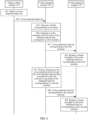
- a process of generating a plurality of rendered images at the first moment refer to step 401 to step 406.
- a process of generating a plurality of rendered images at the second moment refer to step 407 to step 410.
- Step 401 An object culling module 110 performs culling on a plurality of candidate objects based on field of view information of all fields of view at the first moment, to generate a to-be-rendered object set, where the to-be-rendered object set includes a plurality of objects. Each object is marked with a field of view to which the object belongs.
- the field of view information is a spatial location and an FoV that are of a display apparatus 200.
- the object culling module 110 may determine a location and a size of the view frustum based on the field of view information, and may further perform view frustum culling on the plurality of candidate objects, to remove the object outside the view frustum through culling.
- the object culling module 110 performs occlusion culling on the plurality of candidate objects based on the field of view information and a location relationship between the plurality of candidate objects, to cull an occluded candidate object, or cull a part of an occluded candidate object (which is applicable to a case in which only a part of the candidate object is occluded).
- a plurality of objects after the object culling module performs view frustum culling and occlusion culling are objects that need to be displayed in the field of view.
- the object culling module 110 may obtain, by performing a similar operation, a plurality of objects that need to be displayed in each field of view, and the object culling module 110 collects the plurality of objects that need to be displayed in each field of view, to obtain a to-be-rendered object set.
- the to-be-rendered object set includes a plurality of objects, and in the to-be-rendered object set, each object may be marked with a field of view to which the object belongs. For an object that needs to be displayed in a plurality of fields of view, the object is marked with the plurality of fields of view.
- a same object may exist in a plurality of objects that need to be displayed in any two fields of view. In other words, a same object needs to be displayed in a plurality of fields of view. For such an object that may be displayed in a plurality of fields of view, only one object needs to be retained in the to-be-rendered object set, and the object may be marked with the plurality of fields of view. In other words, the to-be-rendered object set does not need to retain a plurality of objects that are same.
- Step 402 The object culling module 110 transmits the to-be-rendered object set to a node clipping module 120.
- Step 403 After obtaining the to-be-rendered object set, the node clipping module 120 generates a DAG corresponding to each object in the to-be-rendered object set for the object.
- the node clipping module 120 may generate a plurality of levels of the object, and then generate a DAG corresponding to the object based on the plurality of levels of the object. Any node in the DAG corresponding to the object represents a cluster of the object at a level of the object.
- each node in the DAG corresponding to the object is also marked with the field of view to which the object belongs.
- the node clipping module 120 may generate a plurality of DAGs corresponding to the object. Each DAG corresponds to one field of view. In other words, a node of each DAG represents a cluster at a level in one field of view.
- Step 404 The node clipping module 120 performs node clipping on the node in the DAG corresponding to each object, to generate a to-be-rendered node list and a to-be-deleted node list that correspond to the first moment.
- the node clipping module 120 When performing node clipping on the node in the DAG corresponding to each object, the node clipping module 120 needs to distinguish a node that can be added to the to-be-rendered node list corresponding to the first moment, a node that can be added to the to-be-deleted node list corresponding to the first moment, and a to-be-discarded node.
- Nodes in the to-be-rendered node list corresponding to the first moment may be divided into a plurality of groups based on a field of view, and a node included in each group represents a cluster of an object that needs to be displayed in one field of view.
- a node in any group meets the following conditions: a screen space error of the node is not greater than an error threshold of the field of view, and a screen space error of a parent node of the node is greater than the error threshold of the field of view.
- the screen space error of the node and the screen space error of the parent node are values related to an attribute of a cluster represented by the node and field of view information of the field of view.
- the error threshold of the field of view may be understood as an allowable display error of an image in the field of view. Error thresholds of different fields of view may be the same or different.
- a specific value of the error threshold of the field of view and a manner of obtaining the error threshold of the field of view are not limited in this embodiment of this application.
- the error threshold of the field of view is default, or may be independently set by a user.
- nodes in the to-be-deleted node list corresponding to the first moment may be divided into a plurality of groups based on the field of view, and a node included in each group represents a cluster of an object that does not need to be displayed in one field of view.
- a node in any group meets the following conditions: a screen space error of the node is not greater than the error threshold of the field of view, and a screen space error of a parent node of the node is not greater than the error threshold of the field of view.
- the screen space error of the node, the screen space error of the parent node, and the error threshold of the field of view refer to the foregoing content. Details are not described herein again.
- a cluster represented by the node in the to-be-deleted node list corresponding to the first moment is a cluster that needs to be displayed in none of the fields of view at the first moment.
- the cluster represented by the node in the to-be-deleted node list corresponding to the first moment may be a cluster that may be displayed in all the fields of view at the second moment. Therefore, the to-be-deleted node list corresponding to the first moment may be retained, to obtain a to-be-rendered node list corresponding to the second moment.
- to-be-discarded nodes may be divided into a plurality of groups based on the field of view, and a node included in each group represents a cluster of an object that needs to be discarded in a field of view.
- a node in any group meets the following condition: a screen space error of the node is greater than an error threshold of the field of view. Such a node is directly discarded, that is, does not need to be added to any node list.
- the node clipping module 120 may first calculate a screen space error of the node and a screen space error of a parent node, and obtain an error threshold of a field of view to which the node belongs.
- the node clipping module 120 may perform the following determining: First, whether the screen space error of the node is not greater than the error threshold of the field of view to which the node belongs is determined (this is a first determining step).
- the screen space error of the node is not greater than the error threshold of the field of view to which the node belongs, whether the screen space error of the parent node of the node is not greater than the error threshold of the field of view to which the node belongs continues to be determined (this is a second determining step). If the screen space error of the parent node of the node is not greater than the error threshold of the field of view to which the node belongs, the node is added to the to-be-deleted node list corresponding to the first moment, and then the node clipping module 120 may continue to extract the parent node of the node to perform determining starting from the first step.
- the node is added to the to-be-rendered node list corresponding to the first moment. If the screen space error of the node is greater than the error threshold of the field of view to which the node belongs, the node is a node that needs to be discarded. For such a node that needs to be discarded, whether the node intersects with the view frustum may continue to be determined. If the node intersects with the view frustum, it indicates that the node is partially located inside the view frustum and may be displayed.
- the node clipping module 120 discards the node, and continues to extract a child node of the node to perform determining starting from the first step. If the node does not intersect with the view frustum, it indicates that the node is located outside the view frustum and is not displayed. The node clipping module 120 may add the node to the to-be-deleted node list corresponding to the first moment.
- the node clipping module 120 may invoke one or more threads to perform step 404.
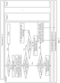
- FIG. 5 is a diagram in which a node clipping module 120 invokes a plurality of threads to perform node clipping. Operations performed by all the threads are similar.
- a thread 0 is used as an example for description.
- the plurality of threads may maintain one node queue.
- the node queue carries a node in a DAG corresponding to an object, the node is identified by N, and different nodes are represented by different subscripts ofN.
- a field of view to which a node belongs is identified by V, and different fields of view are represented by different subscripts of V. Therefore, a node in any DAG may be represented by an array (N i , V i ).
- a node in the DAG corresponding to each object may be randomly added to the node queue.
- the thread 0 may perform the following steps when performing clipping:
- Calculation of the screen error threshold of the node is used as an example.
- field of view information of one field of view is the spatial location and the FoV that are of the display apparatus 200
- the thread 0 may obtain d based on the spatial location of the display apparatus 200 and a cluster represented by the node.
- the FoV is used as ⁇ and is substituted into a calculation formula of the screen error threshold, to obtain the screen error threshold of the node.
- Step 5 The thread 0 determines whether the screen error threshold of the node is not greater than an error threshold of a field of view to which the node belongs, and performs step 6 if the screen error threshold of the node is not greater than the error threshold of the field of view to which the node belongs, or performs step 9 if the screen error threshold of the node is greater than the error threshold of the field of view to which the node belongs.
- Step 6 If the screen error threshold of the node is not greater than the error threshold of the field of view to which the node belongs, the thread 0 determines whether the screen error threshold of the parent node of the node is greater than the error threshold of the field of view to which the node belongs, and performs step 7 if the screen error threshold of the parent node of the node is greater than the error threshold of the field of view to which the node belongs, or performs step 8 if the screen error threshold of the parent node of the node is not greater than the error threshold of the field of view to which the node belongs.
- Step 7 When the screen error threshold of the node is greater than the error threshold of the field of view to which the node belongs, the thread 0 adds the node to the to-be-rendered node list.
- Step 8 If the screen error threshold of the node is not greater than the error threshold of the field of view to which the node belongs, the thread 0 adds all parent nodes of the node to the node queue, and adds the node to the to-be-deleted node list.
- Step 9 When the screen error threshold of the node is greater than the error threshold of the field of view to which the node belongs, the thread 0 determines whether the node intersects with a view frustum of the field of view to which the node belongs, and performs step 10 if the node intersects with the view frustum of the field of view to which the node belongs; or performs step 11 if the node does not intersect with the view frustum of the field of view to which the node belongs.
- Step 10 The thread 0 adds all child nodes of the node to the node queue, and discards the node.
- Step 11 The thread 0 adds the node to the to-be-deleted node list.
- Step 405 The node clipping module 120 transmits the to-be-rendered node list corresponding to the first moment to the node rendering module 130.
- Step 406 The node rendering module 130 renders a cluster included in the to-be-rendered node list corresponding to the first moment, to obtain rendered images at the first moment in the one or more fields of view.
- the node rendering module 130 mainly performs a rendering operation. Because each node in the to-be-rendered node list represents a cluster of an object, the cluster includes a plurality of patches. For any node, the node rendering module 130 may load data of each patch included in the cluster, and render the patch in each cluster based on the loaded data. In this embodiment of this application, a manner in which the patch is rendered is limited. Any manner in which the patch can be rendered is applicable to this embodiment of this application.
- the data of the patch includes a vertex location, a normal, UV coordinates (the UV coordinates indicate a location on a plane represented by an image) that are of a triangle, corresponding texture data, and the like.
- the node rendering module 130 may render each patch by using rasterization rendering.
- a rasterization rendering pipeline is a conceptual model on which rasterization rendering is based.
- the rasterization rendering pipeline describes steps that need to be performed when a rasterized graphics system renders a three-dimensional (3D) scene to a two-dimensional (2D) screen.
- the node rendering module 130 may output the rendered images at the first moment in the one or more fields of view.
- the node rendering module 130 may send a corresponding rendered image to each display apparatus 200, and the display module may display the rendered image at the first moment after obtaining the corresponding rendered image.
- the rendered image at the first moment is generated.
- a rendered image at a next moment of the first moment is generated below.
- the rendered image at the second moment is generated.
- Step 407 The node clipping module 120 performs node clipping on the node in the to-be-rendered node list and the node in the to-be-deleted node list that correspond to the first moment, to generate a to-be-rendered node list and a to-be-deleted node list that correspond to the second moment.
- a node in the to-be-rendered node list corresponding to the second moment meets the following conditions: a screen space error of the node at the second moment is not greater than the error threshold of the field of view, and a screen space error of a parent node of the node at the second moment is greater than the error threshold of the field of view.
- a node in the to-be-deleted node list corresponding to the second moment meets the following conditions: a screen space error of the node at the second moment is not greater than the error threshold of the field of view, and a screen space error of a parent node of the node at the first moment is not greater than the error threshold of the field of view.
- the node clipping module 120 does not need to directly perform node clipping on a DAD of each object, but performs node clipping on the node in the to-be-rendered node list and the node in the to-be-deleted node list that correspond to the first moment.
- the node clipping module 120 When performing node clipping on the node in the to-be-rendered node list and the node in the to-be-deleted node list that correspond to the first moment, the node clipping module 120 needs to distinguish a node that can be added to the to-be-rendered node list corresponding to the second moment, a node that can be added to the to-be-deleted node list corresponding to the second moment, and a to-be-discarded node.
- Nodes in the to-be-rendered node list corresponding to the second moment may be divided into a plurality of groups based on a field of view, and a node included in each group represents a cluster of an object that needs to be displayed in one field of view.
- a node in any group meets the following conditions: a screen space error (the screen space error is a screen space error of the node at the second moment) of the node is not greater than an error threshold of the field of view, and a screen space error (the screen space error is a screen space error of the parent node at the second moment) of a parent node of the node is greater than the error threshold of the field of view.
- nodes in the to-be-deleted node list corresponding to the second moment may be divided into a plurality of groups based on the field of view, and a node included in each group represents a cluster of an object that does not need to be displayed in one field of view.
- a node in any group meets the following conditions: a screen space error of the node is not greater than the error threshold of the field of view, and a screen space error of a parent node of the node is not greater than the error threshold of the field of view.
- to-be-discarded nodes may be divided into a plurality of groups based on the field of view, and a node included in each group represents a cluster of an object that needs to be discarded in a field of view.
- a node in any group meets the following condition: a screen space error of the node is greater than an error threshold of the view. Such a node is directly discarded, that is, does not need to be added to a node list.
- the node clipping module 120 may first calculate a screen space error of the node (the screen space error is a screen space error of the node at the second moment) and a screen space error of a parent node (the screen space error is a screen space error of the parent node at the second moment), and obtain an error threshold of a field of view to which the node belongs.
- the node clipping module 120 may perform the following determining: First, whether the screen space error of the node is not greater than the error threshold of the field of view to which the node belongs is determined (this is a first determining step). If the screen space error of the node is not greater than the error threshold of the field of view to which the node belongs, whether the screen space error of the parent node of the node is not greater than the error threshold of the field of view to which the node belongs continues to be determined (this is a second determining step).
- the node clipping module 120 may extract the parent node of the node to perform determining starting from the first step. If the screen space error of the parent node of the node is greater than the error threshold of the field of view to which the node belongs, the node is added to the to-be-rendered node list corresponding to the second moment. If the screen space error of the node is greater than the error threshold of the field of view to which the node belongs, the node is a node that needs to be discarded.
- whether the node intersects with the view frustum may continue to be determined. If the node intersects with the view frustum, it indicates that the node is partially located inside the view frustum and may be displayed.
- the node clipping module 120 discards the node, and extracts a child node of the node to perform determining starting from the first step. If the node does not intersect with the view frustum, it indicates that the node is located outside the view frustum and is not displayed.
- the node clipping module 120 may add the node to the to-be-deleted node list corresponding to the first moment.
- the node clipping module 120 may also perform, in the manner shown in FIG. 4 , node clipping on the node in the to-be-rendered node list or the to-be-deleted node list corresponding to the first moment.
- a difference lies in that when the node clipping module obtains the to-be-rendered node list or the to-be-deleted node list corresponding to the second moment, initially, the node in the to-be-rendered node list or the to-be-deleted node list corresponding to the first moment may be added to the node queue maintained by the plurality of threads.
- the node clipping module When obtaining the to-be-rendered node list or the to-be-deleted node list corresponding to the second moment, the node clipping module performs node clipping based on the node in the to-be-rendered node list or the to-be-deleted node list corresponding to the first moment.
- the node clipping module performs determining based on a node other than the node in the to-be-rendered node list or the to-be-deleted node list corresponding to the first moment, efficiency of generating the to-be-rendered node list or the to-be-deleted node list corresponding to the second moment can be accelerated, and an obtaining manner is also faster and more convenient.
- FIG. 6A shows a DAG that corresponds to an object and that is generated by the node clipping module 120.
- the DAG corresponding to the object includes 15 nodes, and the 15 nodes change to N0, N1, ..., and N14.
- a node at each level in the DAG represents an LOD of the object.
- the DAG displays four LODs, and the four LODs are an LOD 0, an LOD 1, an LOD 2, and an LOD 3.
- four fields of view namely, V0, V1, V2, and V3, are used as an example.
- FIG. 6A For a relationship between the object and each of the fields of view V0, V1, V2, and V3, refer to FIG. 6A .
- a view frustum of the field of view V1 does not intersect with the object. Therefore, the object in the field of view is discarded in an object culling phase, and a rendered image is not displayed at the first moment in the field of view V1. That is, the V1 field of view is not considered for node clipping.
- nodes retained in the fields of view V0, V2, and V3, namely, nodes in the to-be-rendered node list corresponding to the first moment are as follows:
- Clusters represented by these nodes may be transmitted to the node rendering module 130, and the node rendering module 130 renders the clusters represented by these nodes, to obtain images in the fields of view V0, V2, and V3 at the first moment.
- the fields of view V0, V1, V2, and V3 may move.
- the field of view V3 moves backward and arrives at a location of V3'
- the field of view V2 moves forward and arrives at a location of V2'
- other fields of view remain unchanged is used for description.
- the node clipping module 120 contacts the node in the to-be-rendered node list and the node in the to-be-deleted node list that correspond to the first moment, and nodes retained in the fields of view V0, V2, and V3, namely, nodes in the to-be-rendered node list corresponding to the second moment, are as follows:
- Step 408 The node clipping module 120 transmits the to-be-rendered node list corresponding to the second moment to the node rendering module 130.
- Step 409 The node rendering module 130 renders a cluster represented by each node in the to-be-rendered node list corresponding to the second moment, to generate rendered images at the second moment in the one or more fields of view. For details, refer to a manner of performing step 406. Details are not described herein again.
- the computing device 700 includes a bus 701, a processor 702, a memory 703, and a communication interface 704.
- the processor 702, the memory 703, and the communication interface 704 communicate with each other through the bus 701.
- the computing device 700 may be a server or a terminal device. It should be understood that quantities of processors and memories in the computing device 700 are not limited in this application.
- the bus 701 may be a peripheral component interconnect (peripheral component interconnect, PCI) bus, an extended industry standard architecture (extended industry standard architecture, EISA) bus, or the like. Buses may be classified into an address bus, a data bus, a control bus, and the like. For ease of representation, only one line is used for representation in FIG. 7 , but this does not mean that there is only one bus or only one type of bus.
- the bus 701 may include a path for transmitting information between components (for example, the memory 703, the processor 702, and the communication interface 704) of the computing device 700.
- the processor 702 may include any one or more of processors such as a central processing unit (central processing unit, CPU), a graphics processing unit (graphics processing unit, GPU), a microprocessor (microprocessor, MP), or a digital signal processor (digital signal processor, DSP).
- processors such as a central processing unit (central processing unit, CPU), a graphics processing unit (graphics processing unit, GPU), a microprocessor (microprocessor, MP), or a digital signal processor (digital signal processor, DSP).
- the memory 703 may include a volatile memory (volatile memory), for example, a random access memory (random access memory, RAM).
- the processor 702 may further include a nonvolatile memory (nonvolatile memory), for example, a read-only memory (read-only memory, ROM), a flash memory, a hard disk drive (hard disk drive, HDD), or a solid-state drive (solid-state drive, SSD).
- the memory 703 stores executable program code, and the processor 702 executes the executable program code, to separately implement functions of the object culling module 110, the node clipping module 120, and the node rendering module 130, so as to implement the image rendering method.
- the memory 703 stores instructions used to perform the image rendering method.
- the memory 703 stores executable code, and the processor 702 executes the executable code, to separately implement functions of the rendering apparatus 100, so as to implement the image rendering method.
- the memory 703 stores instructions used to perform the image rendering method.
- the communication interface 704 is a transceiver module, for example, but not limited to, a network interface card or a transceiver, to implement communication between the computing device 700 and another device or a communication network.
- An embodiment of this application further provides a computing device cluster.
- the computing device cluster includes at least one computing device.
- the computing device may be a server, for example, a central server, an edge server, or a local server in a local data center.
- the computing device may alternatively be a terminal device, for example, a desktop computer, a notebook computer, or a smartphone.
- the computing device cluster includes at least one computing device 700.
- the memory 703 in the one or more computing devices 700 in the computing device cluster may store same instructions used to perform the image rendering method.
- the memory 703 in the one or more computing devices in the computing device cluster may also separately store some instructions used to perform the image rendering method.
- a combination of the one or more computing devices 700 may jointly execute the instructions used to perform the image rendering method.
- memories 703 in different computing devices in the computing device cluster may store different instructions respectively used to perform some functions of the rendering apparatus 100.
- the instructions stored in the memory 703 in different computing devices 700 may implement functions of one or more of the object culling module 110, the node clipping module 120, and the node rendering module 130.
- the one or more computing devices in the computing device cluster may be connected through a network.
- the network may be a wide area network, a local area network, or the like.
- An embodiment of this application further provides a computer program product including instructions.
- the computer program product may be a software or program product that includes instructions and that can run on a computing device or be stored in any usable medium.
- the computer program product runs on at least one computing device, the at least one computing device is enabled to perform an application deployment method or an application deployment method.
- Embodiments of this application further provide a computer-readable storage medium.
- the computer-readable storage medium may be any usable medium that can be stored by a computing device, or a data storage device, such as a data center, including one or more usable media.
- the usable medium may be a magnetic medium (for example, a floppy disk, a hard disk, or a magnetic tape), an optical medium (for example, a DVD), a semiconductor medium (for example, a solid-state drive), or the like.
- the computer-readable storage medium includes instructions, and the instructions instruct the computing device to perform an application deployment method or instruct the computing device to perform an application deployment method.
Landscapes
- Engineering & Computer Science (AREA)
- Physics & Mathematics (AREA)
- Theoretical Computer Science (AREA)
- General Physics & Mathematics (AREA)
- Computer Graphics (AREA)
- Artificial Intelligence (AREA)
- Computing Systems (AREA)
- Databases & Information Systems (AREA)
- Evolutionary Computation (AREA)
- General Health & Medical Sciences (AREA)
- Medical Informatics (AREA)
- Software Systems (AREA)
- Computer Vision & Pattern Recognition (AREA)
- Health & Medical Sciences (AREA)
- Multimedia (AREA)
- Spectroscopy & Molecular Physics (AREA)
- Geometry (AREA)
- Image Generation (AREA)
Applications Claiming Priority (2)
| Application Number | Priority Date | Filing Date | Title |
|---|---|---|---|
| CN202210960503.8A CN117635787A (zh) | 2022-08-11 | 2022-08-11 | 一种图像渲染方法、装置及设备 |
| PCT/CN2023/080235 WO2024031977A1 (zh) | 2022-08-11 | 2023-03-08 | 一种图像渲染方法、装置及设备 |
Publications (2)
| Publication Number | Publication Date |
|---|---|
| EP4553776A1 true EP4553776A1 (de) | 2025-05-14 |
| EP4553776A4 EP4553776A4 (de) | 2025-10-22 |
Family
ID=89850539
Family Applications (1)
| Application Number | Title | Priority Date | Filing Date |
|---|---|---|---|
| EP23851213.1A Pending EP4553776A4 (de) | 2022-08-11 | 2023-03-08 | Bilddarstellungsverfahren, -vorrichtung und -einrichtung |
Country Status (4)
| Country | Link |
|---|---|
| US (1) | US20250166349A1 (de) |
| EP (1) | EP4553776A4 (de) |
| CN (1) | CN117635787A (de) |
| WO (1) | WO2024031977A1 (de) |
Families Citing this family (1)
| Publication number | Priority date | Publication date | Assignee | Title |
|---|---|---|---|---|
| CN121053274B (zh) * | 2025-11-03 | 2026-03-17 | 园测信息科技股份有限公司 | 多因子指数衰减的三维模型精度控制与加载方法及系统 |
Family Cites Families (5)
| Publication number | Priority date | Publication date | Assignee | Title |
|---|---|---|---|---|
| JP3724006B2 (ja) * | 1995-04-24 | 2005-12-07 | ダイキン工業株式会社 | 高速レンダリング方法およびその装置 |
| CN110163943B (zh) * | 2018-11-21 | 2024-09-10 | 深圳市腾讯信息技术有限公司 | 图像的渲染方法和装置、存储介质、电子装置 |
| CN112181530A (zh) * | 2020-03-10 | 2021-01-05 | 简吉波 | 基于云平台的虚拟现实场景加载方法及虚拟现实系统 |
| CN113628317A (zh) * | 2020-05-09 | 2021-11-09 | 华为技术有限公司 | 渲染方法、设备以及系统 |
| CN114627219A (zh) * | 2020-12-11 | 2022-06-14 | 中兴通讯股份有限公司 | 三维场景数据的渲染方法及装置、存储介质、电子装置 |
-
2022
- 2022-08-11 CN CN202210960503.8A patent/CN117635787A/zh active Pending
-
2023
- 2023-03-08 WO PCT/CN2023/080235 patent/WO2024031977A1/zh not_active Ceased
- 2023-03-08 EP EP23851213.1A patent/EP4553776A4/de active Pending
-
2025
- 2025-01-17 US US19/030,147 patent/US20250166349A1/en active Pending
Also Published As
| Publication number | Publication date |
|---|---|
| CN117635787A (zh) | 2024-03-01 |
| WO2024031977A1 (zh) | 2024-02-15 |
| US20250166349A1 (en) | 2025-05-22 |
| EP4553776A4 (de) | 2025-10-22 |
Similar Documents
| Publication | Publication Date | Title |
|---|---|---|
| US8773449B2 (en) | Rendering of stereoscopic images with multithreaded rendering software pipeline | |
| US11417060B2 (en) | Stereoscopic rendering of virtual 3D objects | |
| CN114529658B (zh) | 一种图形渲染方法及其相关设备 | |
| AU2020449562B2 (en) | Geometry-aware augmented reality effects with a real-time depth map | |
| US8248412B2 (en) | Physical rendering with textured bounding volume primitive mapping | |
| EP4172862A1 (de) | Neuronales netzwerk zur objekterkennung für amodale zentrale vorhersage | |
| CN113379886B (zh) | 地理信息系统的三维渲染方法、装置、设备及存储介质 | |
| CN114332250A (zh) | 使用时间累积来对动态光线追踪场景进行去噪的历史箝位 | |
| US20230230311A1 (en) | Rendering Method and Apparatus, and Device | |
| EP3959689A1 (de) | Effiziente wiedergabe hochdichter netze | |
| US12112533B2 (en) | Method and apparatus for data calculation in neural network model, and image processing method and apparatus | |
| US20250166349A1 (en) | Image rendering method, apparatus, and device | |
| Hahlbohm et al. | Efficient Perspective‐Correct 3D Gaussian Splatting Using Hybrid Transparency | |
| DE102023105068A1 (de) | Bewegungsvektoroptimierung für mehrfach refraktive und reflektierende Schnittstellen | |
| CN116664648A (zh) | 点云帧及深度图生成方法、装置、电子设备和存储介质 | |
| US12597198B2 (en) | Ray tracing method and apparatus based on attention for dynamic scenes | |
| CN115359170A (zh) | 场景数据的生成方法、装置、电子设备和存储介质 | |
| US9117254B2 (en) | System, method, and computer program product for performing ray tracing | |
| CN110838167B (zh) | 模型的渲染方法、装置和存储介质 | |
| US9639975B1 (en) | System and method for generating shadows | |
| JP2023539808A (ja) | 深度カリングを呼び出すためのシェーダコア命令 | |
| Schick et al. | Real-time GPU-based voxel carving with systematic occlusion handling | |
| CN118262313A (zh) | 道路区域检测方法、装置及电子设备 | |
| CN117496030A (zh) | 虚拟场景的渲染方法、装置、电子设备及存储介质 | |
| CN114882510A (zh) | 一种具有防攻功能的瓦楞纸箱商标鲁棒检测方法 |
Legal Events
| Date | Code | Title | Description |
|---|---|---|---|
| STAA | Information on the status of an ep patent application or granted ep patent |
Free format text: STATUS: THE INTERNATIONAL PUBLICATION HAS BEEN MADE |
|
| PUAI | Public reference made under article 153(3) epc to a published international application that has entered the european phase |
Free format text: ORIGINAL CODE: 0009012 |
|
| STAA | Information on the status of an ep patent application or granted ep patent |
Free format text: STATUS: REQUEST FOR EXAMINATION WAS MADE |
|
| 17P | Request for examination filed |
Effective date: 20250204 |
|
| AK | Designated contracting states |
Kind code of ref document: A1 Designated state(s): AL AT BE BG CH CY CZ DE DK EE ES FI FR GB GR HR HU IE IS IT LI LT LU LV MC ME MK MT NL NO PL PT RO RS SE SI SK SM TR |
|
| REG | Reference to a national code |
Ref country code: DE Ref legal event code: R079 Free format text: PREVIOUS MAIN CLASS: G06T0015000000 Ipc: G06T0015300000 |
|
| A4 | Supplementary search report drawn up and despatched |
Effective date: 20250919 |
|
| RIC1 | Information provided on ipc code assigned before grant |
Ipc: G06T 15/30 20110101AFI20250915BHEP |
|
| DAV | Request for validation of the european patent (deleted) | ||
| DAX | Request for extension of the european patent (deleted) |