EP4553780A2 - Appareil de vérification et/ou d'identification biométriques - Google Patents
Appareil de vérification et/ou d'identification biométriques Download PDFInfo
- Publication number
- EP4553780A2 EP4553780A2 EP24206345.1A EP24206345A EP4553780A2 EP 4553780 A2 EP4553780 A2 EP 4553780A2 EP 24206345 A EP24206345 A EP 24206345A EP 4553780 A2 EP4553780 A2 EP 4553780A2
- Authority
- EP
- European Patent Office
- Prior art keywords
- biometric
- processing unit
- camera
- unit
- camera unit
- Prior art date
- Legal status (The legal status is an assumption and is not a legal conclusion. Google has not performed a legal analysis and makes no representation as to the accuracy of the status listed.)
- Pending
Links
Images



Classifications
-
- G—PHYSICS
- G06—COMPUTING OR CALCULATING; COUNTING
- G06V—IMAGE OR VIDEO RECOGNITION OR UNDERSTANDING
- G06V10/00—Arrangements for image or video recognition or understanding
- G06V10/70—Arrangements for image or video recognition or understanding using pattern recognition or machine learning
- G06V10/77—Processing image or video features in feature spaces; using data integration or data reduction, e.g. principal component analysis [PCA] or independent component analysis [ICA] or self-organising maps [SOM]; Blind source separation
- G06V10/80—Fusion, i.e. combining data from various sources at the sensor level, preprocessing level, feature extraction level or classification level
- G06V10/809—Fusion, i.e. combining data from various sources at the sensor level, preprocessing level, feature extraction level or classification level of classification results, e.g. where the classifiers operate on the same input data
- G06V10/811—Fusion, i.e. combining data from various sources at the sensor level, preprocessing level, feature extraction level or classification level of classification results, e.g. where the classifiers operate on the same input data the classifiers operating on different input data, e.g. multi-modal recognition
-
- G—PHYSICS
- G02—OPTICS
- G02B—OPTICAL ELEMENTS, SYSTEMS OR APPARATUS
- G02B3/00—Simple or compound lenses
- G02B3/12—Fluid-filled or evacuated lenses
- G02B3/14—Fluid-filled or evacuated lenses of variable focal length
-
- G—PHYSICS
- G06—COMPUTING OR CALCULATING; COUNTING
- G06V—IMAGE OR VIDEO RECOGNITION OR UNDERSTANDING
- G06V10/00—Arrangements for image or video recognition or understanding
- G06V10/10—Image acquisition
- G06V10/12—Details of acquisition arrangements; Constructional details thereof
- G06V10/14—Optical characteristics of the device performing the acquisition or on the illumination arrangements
- G06V10/147—Details of sensors, e.g. sensor lenses
-
- G—PHYSICS
- G06—COMPUTING OR CALCULATING; COUNTING
- G06V—IMAGE OR VIDEO RECOGNITION OR UNDERSTANDING
- G06V40/00—Recognition of biometric, human-related or animal-related patterns in image or video data
- G06V40/10—Human or animal bodies, e.g. vehicle occupants or pedestrians; Body parts, e.g. hands
- G06V40/12—Fingerprints or palmprints
- G06V40/13—Sensors therefor
- G06V40/1312—Sensors therefor direct reading, e.g. contactless acquisition
-
- G—PHYSICS
- G06—COMPUTING OR CALCULATING; COUNTING
- G06V—IMAGE OR VIDEO RECOGNITION OR UNDERSTANDING
- G06V40/00—Recognition of biometric, human-related or animal-related patterns in image or video data
- G06V40/10—Human or animal bodies, e.g. vehicle occupants or pedestrians; Body parts, e.g. hands
- G06V40/16—Human faces, e.g. facial parts, sketches or expressions
- G06V40/161—Detection; Localisation; Normalisation
- G06V40/166—Detection; Localisation; Normalisation using acquisition arrangements
-
- G—PHYSICS
- G06—COMPUTING OR CALCULATING; COUNTING
- G06V—IMAGE OR VIDEO RECOGNITION OR UNDERSTANDING
- G06V40/00—Recognition of biometric, human-related or animal-related patterns in image or video data
- G06V40/10—Human or animal bodies, e.g. vehicle occupants or pedestrians; Body parts, e.g. hands
- G06V40/18—Eye characteristics, e.g. of the iris
- G06V40/19—Sensors therefor
Definitions
- the invention relates to a device for biometric verification and/or identification using fingerprint features and/or facial features.
- the device comprises a camera with one or more liquid lenses or solid-state lenses, one or more illumination units, one or more proximity sensors, a display unit, a main circuit board for evaluation, optionally a 3D camera, and optionally a contactless reader for biometric identity documents.
- a biometric identity document is understood to be, for example, a biometric passport or a biometric identity card.
- This device is intended for access control, border control, and identification and/or verification of a person, for example, in a mobile version for police officers.
- Biometric identification and/or verification using fingerprints and/or facial features is a fundamentally well-known method that is based on the very low probability that two people have the same fingerprints and/or facial features.
- biometric samples from fingerprints is possible either by (i) contact (i.e., the person places a finger or the whole hand on a specific scanning surface of a scanning device, which takes an image of the finger and/or hand) or (ii) non-contact (i.e., the recording device takes an image of the finger and/or hand over a distance, i.e., without the person having to touch the parts of the
- contact-based methods and devices is the risk of incorrect identification (or verification) due to contamination of the contact surface of the recording device.
- the skin on the fingertip can change elasticity, which is closely related to the pressure exerted on the finger.
- the second major disadvantage is the possibility of bacteria and viruses being transmitted from the surface of the device to other users. This makes it an unhygienic solution. Therefore, contactless methods and devices for biometric identification and/or verification based on fingerprints have recently been developed. Devices for facial identification and/or verification are, of course, contactless due to the nature of the scanning process.
- the captured fingerprint(s) and facial images are then processed to compare them with the biometric patterns of registered persons stored in the database or with the pattern stored in the biometric identity document.
- the object of the present invention is to provide a novel device for the biometric verification and/or biometric identification of a person and a novel method for its operation.
- the object is achieved according to the invention by a device for the biometric verification and/or biometric identification of a person with the Features of claim 1 and by a method having the features of claim 11.
- the contactless, multimodal biometric device further comprises a first illumination unit, in particular in the form of an array of lights, which are arranged in particular at a uniform angular distance around the first lens.
- the contactless multimodal biometric device further comprises a second camera unit having a second camera sensor and a second lens connected to the processing unit.
- the first lens and/or the second lens is/are a liquid lens or a lens with a motorized focusing mechanism.
- the contactless, multimodal biometric device comprises a front face (e.g., on a housing) on which the second camera unit is arranged and, below the front face, an entrance to the open cavity in which a mirror is arranged to reflect the space scanned by the first camera unit in the open cavity.
- the contactless, multimodal biometric device further comprises a reader connected to the processing unit for reading biometric identity documents, in particular chips arranged therein.
- the reader may have an antenna for this purpose.
- the contactless multimodal biometric device further comprises a display unit for displaying the identification results and/or verification results, connected to the processing unit.
- the contactless, multimodal biometric device further comprises a 3D camera arranged to capture the area outside the biometric device and connected to the processing unit.
- a method for operating the multimodal biometric device described above wherein, by means of the first camera unit, multiple images of the palm of a hand with multiple focal planes, in which the palm and/or fingertips of the fingers of the hand are located, are captured and transmitted to the processing unit, which performs biometric identification.
- Biometric verification can be referred to as a comparison in which an assumed or alleged identity of a person is to be verified. This involves comparing currently read biometric data with a stored biometric pattern (if available) of the specific person.
- Biometric identification refers to the determination of the person's identity. If necessary, all biometric patterns stored in a database must be reviewed in order to declare the biometric pattern with the best comparison score as the found identity. If the comparison score does not exceed a predetermined minimum threshold, then the identity has not been found. In the case of biometric ID documents, this always involves verification.
- a plurality of sets, for example three sets, of images of the palm of the hand are acquired with a plurality of focal planes in which the palm of the hand and/or fingertips are located, wherein a first set is acquired when the palm of the hand is in a first position in the at right angles to an optical axis of the first camera unit, with a second set being recorded when the hand has been rotated to the left from this position about a proximal-distal axis, and a third set being recorded when the hand has been rotated to the right from the first position about the proximal-distal axis.
- the proximal-distal axis can, for example, be an axis passing through an extended middle finger of the user.
- the user can be prompted to move his hand into the different positions by outputs on the display unit.
- a machine-readable area of a page of a biometric identity document is captured by means of the first or second camera unit, wherein characters present in the machine-readable area are recognized by the processing unit and a key contained therein is extracted, wherein data is read from a chip present in the biometric identity document by means of the reading device using the key.
- At least one image of a user's face is captured by the second camera unit, triggered by the proximity sensor, using the lighting unit and transmitted to the processing unit by which the biometric identification is carried out.
- At least one image of a right iris and/or a left iris of a user is captured by the second camera unit, triggered by the proximity sensor, using the illumination unit and transmitted to the processing unit by which the biometric identification is carried out.
- fingerprints and/or a palm print are/are determined from the recorded images of the palm of the hand, wherein the determined fingerprints and/or the determined palm print are/are compared with a biometric pattern from the data read from the chip.
- This process is called biometric verification of the user's claimed identity and is based on fingerprints and/or palm prints, using the biometric identity document as a reference.
- the captured image of the face and/or the image of the right iris and/or the left iris is/are compared with a biometric pattern from the data read from the chip.
- This process is called biometric verification of the user's claimed identity and is based on images of the face and/or the right iris and/or a left iris, using the biometric identity document as a reference.
- biometric modalities can be provided in a single device.
- Groups of all biometric modalities i.e., at least one fingerprint, one palm print, one facial image, and/or at least one iris image—comprising two, three, or four of the modalities can be combined in any order.
- the 3D camera is used to check a position and an orientation of the user's hand and/or head and to provide feedback to the user requesting that the position and/or orientation be corrected.
- Data acquired by the 3D camera can also be used for biometric recognition of the three-dimensional structure of the head and/or the three-dimensional geometry of the hand.
- the device described in the present application requires little space, can be mounted, for example, on a wall, is contactless and enables the recording of at least one significant biometric feature (for example, two significant biometric features) and supports the use of biometric identity documents.
- the device is modular and allows the capture and recognition of fingerprints or faces, or at least combines these two biometric features in a single biometric recognition process.
- This basic configuration can be expanded through the optional use of biometric identity documents and/or the optional use of a 3D camera.
- the 3D camera can be used to ensure the precise position and orientation of the captured biometric features and can also enable the capture and recognition of a 3D facial geometry and/or a 3D hand geometry, including subsequent biometric recognition.
- the approaching hand is detected by a proximity sensor.
- the proximity sensor triggers the start of the hand recording with different focal planes to ensure the sharpness of the images of individual fingers, which may be differently oriented in space (it is difficult to position all fingertips in the same plane).
- These fingerprints are then processed and the Identification or verification is performed.
- the illumination unit can be adjusted according to the shape (circular or rectangular), location, wavelength(s) used, particularly infrared or green, and the required illumination intensity to ensure a high-quality image of the upper part of the hand (i.e., the fingers or fingertips).
- the illumination unit can be adjusted with regard to the shape (circular or rectangular) and/or location of the area to be illuminated, the wavelength(s) used, and the required illuminance.
- the settings should be selected to avoid eye damage or user discomfort.
- the combination of fingerprints and facial recognition is an interesting advantage enabled by the use of a multimodal biometric device.
- the lighting unit should be adjusted according to the intended use and with user safety in mind.
- PAD Presentation Attack Detection
- multispectral detection using selected wavelengths
- a neural network can be trained to recognize various patterns in the image that may indicate a forgery (e.g., bubbles in the material, curvature of the fingerprint lines, sharp edges of the forgery, and the like).
- biometric data stored in the biometric pattern of a biometric identity document Another option is verification using biometric data stored in the biometric pattern of a biometric identity document.
- the front of the biometric identity document is scanned by a camera to detect the MRZ (Machine Readable Zone) using optical character recognition (OCR).
- OCR optical character recognition
- the MRZ contains the key to access publicly available data contained in a chip of the identity document (e.g., the user's personal data and/or a facial image). Access to protected data contained in the chip requires a special certificate, which can be provided by authorized authorities.
- a radio unit RFID/NFC
- Reading the data from the identity document can take ten seconds or more; the document can be placed against the device to securely read the data.
- the biometric data just recorded is then compared with the data of the biometric pattern stored in the biometric identity document.
- All variants of the device can be equipped with a 3D camera, which enables the precise determination of the position of the hand and/or face in front of the device. This allows the user to correct the position of their hand and/or face. Furthermore, it can enable the recognition of 3D data of the face and/or hand, i.e., additional information for multimodal biometric recognition. Likewise, the 3D camera can serve as an additional module for the PAD (protection against tools for presentation attacks, which can be particularly two-dimensional or three-dimensional with low quality).
- the Figure 1C The variant shown can be set up for left-handed or right-handed people.
- a display unit of the device can be designed to be touch-sensitive (touch display) and/or an arrangement of position sensors (for example proximity sensors) can be arranged around the display unit, whereby a touch-free control of the device is possible without a touch-sensitive display unit, for example with a working distance of approximately 5 cm from the device.
- position sensors for example proximity sensors
- FIGS. 1A to 1D show schematic illustrations of different embodiments of a device 1 for biometric verification and/or identification, in particular respective views of a front side.
- FIG. 1A One in Figure 1A The variant of device 1 shown supports the recording of fingerprints, faces and identity documents using a camera located on the front.
- FIG. 1C The variant shown essentially corresponds to the one in Figure 1B shown variant, wherein the camera and the lighting units 9 for recording the fingerprints (optionally also the camera unit 3 and the proximity sensor 10) are arranged on a right side in a beveled edge of the device 1.
- the camera and the lighting units 9 for recording the fingerprints can also be arranged on a left side in a beveled edge of the device 1.
- FIG. 1D The variant shown is similar to the one in Figure 1C shown variant, but wherein the camera and the lighting units 9 for recording the fingerprints (if applicable also the camera unit 3 and the proximity sensor 10) are arranged on an underside of the device 1 and are directed downwards, for example in the direction of a floor or substrate.
- the camera and the lighting units 9 for recording the fingerprints are arranged on an underside of the device 1 and are directed downwards, for example in the direction of a floor or substrate.
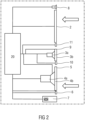
- Figure 2 is a schematic view of the device 1 for biometric verification and/or identification without a mirror 12 with a plurality of possible components or with all possible components, some of which may be optional.
- the invention is described below with reference to embodiments of a device 1 for biometric verification and/or identification based on fingerprints and/or a face and with reference to a method for operating the device 1.
- Figure 4 is a schematic view of an exemplary design of the device 1 for biometric verification and/or identification.
- Example 1 is based on the Figure 1A shown variant.
- the device 1 has a display unit 2, a camera unit 4 (for example, a camera 4a with lens 4b), a lighting unit 5, and a proximity sensor 6.
- This configuration is suitable for recording fingerprints and subsequent identification.
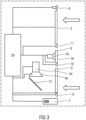
- a user's hand approaches the device 1, the proximity sensor 6 detects the hand, and transmits a distance from the hand to the proximity sensor 6 to a Figures 2 and 3 processing unit 20 shown.
- the camera unit 4 comprises a camera 4a and an objective 4b or a lens 4b, for example a liquid lens or a motorized lens (see Figures 2 and 3 ).
- the lens 4b is set to the distance provided by the proximity sensor 6 and the lens 4b of the camera unit 4 is automatically focused on the hand and the fingers are recorded by the camera 4a (see Figures 2 and 3 ).
- This captured image is transmitted to the processing unit 20, where finger regions of interest are extracted and fingerprints are compared with all stored patterns in a database of registered users or with a provided biometric pattern from a biometric document.
- the result of the comparison is displayed on the display unit 2. For example, the identity is displayed if the comparison was positive; otherwise, information about unsuccessful identification is displayed.
- Device 1 can also send this result to an API (Application Programming Interface), for example to open a gate.
- API Application Programming Interface
- Example 2 is based on Example 1, but additionally uses facial recognition.
- the face with an open hand on the right or left side of the head with the palm facing towards the device 1 is approached by the proximity sensor 6 in the device 1, which starts the recording similarly to the description in Example 1.
- two biometric images are taken – one is fingerprints (from the fingertips of the open hand) and the other is a face image.
- the recognition of these two biometric images takes place in the processing unit 20 (see Figures 2 and 3 ), where a decision fusion is also performed.
- a decision fusion both results from the comparisons (face and fingerprint) are combined. In reality, the fingerprint has higher reliability and is therefore often more important for the decision.
- the rest of the process (displaying the result and/or communicating with an API) is similar to Example 1.
- Example 3 is based on Example 1, but additionally provides a reader 7 for personal identity cards. Operation corresponds to the description for Example 1, but with a further option - the user can use their BID (biometric identity document) and present it to the camera unit 4, whereupon the proximity sensor 6 detects the object approaching the device 1 and sends the distance information to the processing unit 20, which controls the lens 4b (in particular, a liquid lens). The camera 4a records the front of a biometric identity document. Subsequently, the processing unit 20 recognizes the characters in a machine-readable zone (MRZ) of the biometric identity document.
- MMRZ machine-readable zone
- the user can then be prompted (for example, via an output on the display unit 2) to bring the biometric identity document closer to a corner of the device 1, behind which the object marked with a symbol of a A reader 7 identified by the biometric identity document is arranged, so that the radio-based reader 7 can receive information from a chip of the biometric identity document using a key determined from the characters of the machine-readable zone and subsequently transmit it to the processing unit 20.
- the user can then be asked to present their hand for fingerprint capture (similar to the description for example 1). This involves a comparison of the captured biometric data and the sample data of biometric characteristics read from the chip of the biometric identity document. If a match is found, the identity of the holder of the biometric identity document is confirmed.
- the rest of the process (display of the result and/or communication with an API) is similar to example 1.
- Example 4 is a combination of examples 2 and 3.
- Example 5 is based on Example 2. The only difference from Example 2 is that an additional camera unit 3 is provided, which is used separately for facial recognition, while camera unit 4 is used for fingerprint recognition. Two differently designed lenses 4b, 3b and/or two differently designed cameras 4a, 3a (for example, with regard to resolution and/or frame rate) can be used, for example, with differently designed illumination units 5, 9. Fingerprints, for example, are captured closer to device 1, while the face is captured from a greater distance.
- Example 6 is based on Example 4. The only difference from Example 4 is that an additional camera unit 4 is provided, which is used separately for facial recognition, while camera unit 3 is used for capturing fingerprints and recording the biometric identity document.
- Two differently designed lenses 4b, 3b and/or two differently designed cameras 4a, 3a (for example in terms of resolution and/or refresh rate), for example with differently designed lighting units 5, 9. Fingerprints and the biometric identity document, for example, are captured closer to the device 1, whereas the face is captured from a greater distance.
- Example 7 is based on Example 5.
- the only difference from Example 5 is that the camera unit 3 with the lighting unit 9 and a proximity sensor 10 is oriented laterally (left or right), particularly in relation to the orientation of the camera unit 4.
- the reason for this configuration may be a possible use of visible light (for lighting and/or for PAD - Presentation Attack Detection), which could dazzle the user if used frontally. Invisible light could also be used here.
- the lateral orientation of the camera unit 3 with the lighting unit 9 and the proximity sensor 10 at an angle ensures that the light does not fall directly onto the user's eyes.
- the lateral camera unit 3 with the lighting unit 9 and the proximity sensor 10 can, for example, only be used for capturing fingerprints and/or the biometric identity document.
- the forward-facing camera unit 4 with the lighting unit 5 and the proximity sensor 6 can, for example, only be used for capturing the face and/or the biometric identity document.
- Example 8 is based on Example 6.
- the only difference from Example 6 is that the camera unit 3 with the lighting unit 9 and the proximity sensor 10 is aligned laterally (left or right), particularly in relation to the orientation of the camera unit 4.
- the reason for this configuration may be a possible use of visible light (for lighting and/or for PAD - Presentation Attack Detection), which could dazzle the user when used frontally.
- the lateral alignment of the camera unit 3 with the lighting unit 9 and the proximity sensor 10 at an angle ensures that the light does not fall directly onto the user's eyes.
- the lateral camera unit 3 with the The illumination unit 9 and the proximity sensor 10 can, for example, be used only for capturing fingerprints and/or the biometric identity document.
- the front-facing camera unit 4 with the illumination unit 5 and the proximity sensor 6 can, for example, be used only for capturing the face and/or the biometric identity document.
- Example 9 is based on Example 5.
- the only difference from Example 5 is that the camera unit 3 with the lighting unit 9 and the proximity sensor 10 is oriented downwards, particularly in relation to the orientation of the camera unit 4.
- the reason for this configuration may be the possible use of visible light (for lighting and/or for PAD - Presentation Attack Detection), which could dazzle the user if used frontally.
- the orientation of the camera unit 3 with the lighting unit 9 and the proximity sensor 10 at a downward angle ensures that the light does not fall directly onto the user's eyes.
- the downward-facing camera unit 3 with the lighting unit 9 and the proximity sensor 10 can, for example, only be used for capturing fingerprints and/or the biometric identity document.
- the forward-facing camera unit 4 with the lighting unit 5 and the proximity sensor 6 can, for example, only be used for capturing the face and/or the biometric identity document.
- Example 10 is based on Example 6.
- the only difference from Example 6 is that the camera unit 3 with the illumination unit 9 and the proximity sensor 10 is oriented downwards, particularly in relation to the orientation of the camera unit 4.
- the reason for this configuration may be a possible use of visible light (for illumination and/or for PAD - Presentation Attack Detection), which could dazzle the user when used frontally.
- the downward-facing camera unit 3 with the illumination unit 9 and the proximity sensor 10 can, for example, only be used for capturing fingerprints and/or the biometric identity document.
- the forward-facing camera unit 4 with the illumination unit 5 and the proximity sensor 6 can, for example, only be used for capturing the face and/or the biometric identity document.
- FIG. 1A to 1D The embodiments shown can be adapted Figure 2 and/or Figure 3 with or without a mirror 12 and have a touch-sensitive display unit 2 (touch display), in particular when there is no need to use an array of proximity sensors 11, but the display unit 2 is to be touched with the user's fingers, in particular for operating the device 1.
- a contactless display unit 2 can be used.
- an array of proximity sensors 11 can be provided, which serves to detect a finger at a distance of a few centimeters from the device 1 for controlling the display unit 2.
- All of the examples described above can further be equipped with a 3D camera 8, which can be used for precise positioning of the hand for recording fingerprints and/or facial recognition, for example, including detecting the correct position and distance of these biometric features and the biometric identity document.
- the 3D camera 8 can also be used for three-dimensional biometric recognition, in particular of the face and/or head, and the spatial geometry of the hand.
- Figure 2 differs from Figure 3 in that in Figure 3 a mirror 12 (for example, a front surface mirror) is provided. If the focal plane of the camera unit 4 (camera 4a with lens 4b) is too far away from the device 1 or a mirror 12 can be used to extend the optical path.
- a mirror 12 for example, a front surface mirror
- the reader 7 or the antenna 7 for reading the biometric identity document can be arranged in different positions, as shown in the Figures 1A to 1D is shown. Another option is to arrange the antenna 7 around the lighting unit 5 or 9. The advantage of this is that the user presents the biometric identity document to the camera unit 4 or 3, and as the biometric identity document approaches closer to the device 1, not only is optical information read from the biometric identity document, but the radio information can subsequently be read directly from the chip of the biometric identity document.
Landscapes
- Engineering & Computer Science (AREA)
- Physics & Mathematics (AREA)
- General Physics & Mathematics (AREA)
- Theoretical Computer Science (AREA)
- Multimedia (AREA)
- Health & Medical Sciences (AREA)
- General Health & Medical Sciences (AREA)
- Human Computer Interaction (AREA)
- Computer Vision & Pattern Recognition (AREA)
- Vascular Medicine (AREA)
- Ophthalmology & Optometry (AREA)
- Oral & Maxillofacial Surgery (AREA)
- Optics & Photonics (AREA)
- Artificial Intelligence (AREA)
- Computing Systems (AREA)
- Databases & Information Systems (AREA)
- Evolutionary Computation (AREA)
- Medical Informatics (AREA)
- Software Systems (AREA)
- Collating Specific Patterns (AREA)
- Image Input (AREA)
- Measurement Of The Respiration, Hearing Ability, Form, And Blood Characteristics Of Living Organisms (AREA)
Applications Claiming Priority (2)
| Application Number | Priority Date | Filing Date | Title |
|---|---|---|---|
| CZ2023-41396U CZ37555U1 (cs) | 2023-10-19 | 2023-10-19 | Bezkontaktní multimodální biometrické zařízení |
| DE102023136019.1A DE102023136019A1 (de) | 2023-10-19 | 2023-12-20 | Gerät zur biometrischen Verifizierung und/oder Identifizierung |
Publications (2)
| Publication Number | Publication Date |
|---|---|
| EP4553780A2 true EP4553780A2 (fr) | 2025-05-14 |
| EP4553780A3 EP4553780A3 (fr) | 2025-07-16 |
Family
ID=93119800
Family Applications (1)
| Application Number | Title | Priority Date | Filing Date |
|---|---|---|---|
| EP24206345.1A Pending EP4553780A3 (fr) | 2023-10-19 | 2024-10-14 | Appareil de vérification et/ou d'identification biométriques |
Country Status (1)
| Country | Link |
|---|---|
| EP (1) | EP4553780A3 (fr) |
Family Cites Families (3)
| Publication number | Priority date | Publication date | Assignee | Title |
|---|---|---|---|---|
| CN105320943A (zh) * | 2015-10-22 | 2016-02-10 | 北京天诚盛业科技有限公司 | 生物识别装置及其进行生物识别的方法 |
| CN108764093B (zh) * | 2018-05-21 | 2021-06-04 | 中国人民解放军战略支援部队信息工程大学 | 基于相机的非接触指纹图像采集装置及方法 |
| AT521935A1 (de) * | 2018-12-05 | 2020-06-15 | Ait Austrian Inst Tech Gmbh | Verfahren zur Erfassung von Fingerabdrücken |
-
2024
- 2024-10-14 EP EP24206345.1A patent/EP4553780A3/fr active Pending
Also Published As
| Publication number | Publication date |
|---|---|
| EP4553780A3 (fr) | 2025-07-16 |
Similar Documents
| Publication | Publication Date | Title |
|---|---|---|
| DE10362243B4 (de) | Personenerkennungsvorrichtung und -system | |
| EP3047424B1 (fr) | Dispositif, système et procédé d'identification d'un individu | |
| DE60220494T2 (de) | Verfahren zur Iriserkennung und System unter Verwendung desselben | |
| DE60209050T2 (de) | Gerät und Verfahren zur Anpassung der Fokusposition in einem Iriserkennungssystem | |
| EP2977925B1 (fr) | Terminal mobile destine a enregistrer des donnees biometriques | |
| WO2014131635A1 (fr) | Dispositif permettant d'acquérir des données personnelles | |
| WO1999056237A1 (fr) | Systeme pour la reconnaissance sans contact des lignes de la main et des doigts | |
| EP3425560B1 (fr) | Dispositif et procédé de détection des caractéristiques biométriques d'un visage d'une personne | |
| DE102014112494B4 (de) | Vorrichtung zur Erfassung biometrischer Merkmale eines Gesichts einer Person | |
| CN105320932A (zh) | 虹膜识别终端及方法 | |
| EP3889834A2 (fr) | Système d'authentification basé sur les signaux d'activité cérébrale | |
| DE102023136019A1 (de) | Gerät zur biometrischen Verifizierung und/oder Identifizierung | |
| EP1408441A2 (fr) | Dispositif de saisie optique sans contact de propriétés biométriques d'au moins une partie du corps | |
| DE102019135107A1 (de) | Vorrichtung und verfahren zum bestimmen eines biometrischen merkmals eines gesichts einer person | |
| EP3671543B1 (fr) | Appareil de détection des caractéristiques biométriques d'un visage d'une personne | |
| EP4341918B1 (fr) | Dispositif et procédé pour produire une image biométrique du visage d'une personne | |
| EP4553780A2 (fr) | Appareil de vérification et/ou d'identification biométriques | |
| KR102176882B1 (ko) | 특징점 변동을 이용한 위조 홍채 판별장치 및 그 방법 | |
| WO2019072672A1 (fr) | Système de contrôle d'une personne | |
| EP3789916B1 (fr) | Dispositif et procédé de détection des caractéristiques biométriques d'un visage d'une personne | |
| KR102594852B1 (ko) | 적외선을 이용하여 위조얼굴을 구별할 수 있는 얼굴인식장치 및 그 얼굴인식방법 | |
| EP3836015A1 (fr) | Système de capteur permettant de vérifier les motifs de veines de la main | |
| Singla et al. | Challenges at different stages of an iris based biometric system. | |
| WO2005013183A2 (fr) | Dispositif de determination, d'identification et de verification biometrique de personnes sur la base des traces des stries cutanees sur la face inferieure des phalanges | |
| EP3499865B1 (fr) | Dispositif et procédé de mesure des données d'image |
Legal Events
| Date | Code | Title | Description |
|---|---|---|---|
| PUAI | Public reference made under article 153(3) epc to a published international application that has entered the european phase |
Free format text: ORIGINAL CODE: 0009012 |
|
| STAA | Information on the status of an ep patent application or granted ep patent |
Free format text: STATUS: THE APPLICATION HAS BEEN PUBLISHED |
|
| AK | Designated contracting states |
Kind code of ref document: A2 Designated state(s): AL AT BE BG CH CY CZ DE DK EE ES FI FR GB GR HR HU IE IS IT LI LT LU LV MC ME MK MT NL NO PL PT RO RS SE SI SK SM TR |
|
| PUAL | Search report despatched |
Free format text: ORIGINAL CODE: 0009013 |
|
| AK | Designated contracting states |
Kind code of ref document: A3 Designated state(s): AL AT BE BG CH CY CZ DE DK EE ES FI FR GB GR HR HU IE IS IT LI LT LU LV MC ME MK MT NL NO PL PT RO RS SE SI SK SM TR |
|
| RIC1 | Information provided on ipc code assigned before grant |
Ipc: G06V 10/147 20220101AFI20250612BHEP Ipc: G02B 3/14 20060101ALI20250612BHEP Ipc: G02B 26/00 20060101ALI20250612BHEP Ipc: G06V 10/80 20220101ALI20250612BHEP Ipc: G06V 40/13 20220101ALI20250612BHEP Ipc: G06V 40/16 20220101ALI20250612BHEP Ipc: G06V 40/19 20220101ALI20250612BHEP |