EP4553794A1 - Verfahren, vorrichtung und vorrichtung zur überwachung eines fahrblindpunkts und lesbares speichermedium - Google Patents
Verfahren, vorrichtung und vorrichtung zur überwachung eines fahrblindpunkts und lesbares speichermedium Download PDFInfo
- Publication number
- EP4553794A1 EP4553794A1 EP24785958.0A EP24785958A EP4553794A1 EP 4553794 A1 EP4553794 A1 EP 4553794A1 EP 24785958 A EP24785958 A EP 24785958A EP 4553794 A1 EP4553794 A1 EP 4553794A1
- Authority
- EP
- European Patent Office
- Prior art keywords
- grayscale
- area
- images
- value
- frames
- Prior art date
- Legal status (The legal status is an assumption and is not a legal conclusion. Google has not performed a legal analysis and makes no representation as to the accuracy of the status listed.)
- Pending
Links
Images


Classifications
-
- G—PHYSICS
- G08—SIGNALLING
- G08G—TRAFFIC CONTROL SYSTEMS
- G08G1/00—Traffic control systems for road vehicles
- G08G1/16—Anti-collision systems
- G08G1/167—Driving aids for lane monitoring, lane changing, e.g. blind spot detection
-
- B—PERFORMING OPERATIONS; TRANSPORTING
- B60—VEHICLES IN GENERAL
- B60R—VEHICLES, VEHICLE FITTINGS, OR VEHICLE PARTS, NOT OTHERWISE PROVIDED FOR
- B60R1/00—Optical viewing arrangements; Real-time viewing arrangements for drivers or passengers using optical image capturing systems, e.g. cameras or video systems specially adapted for use in or on vehicles
- B60R1/20—Real-time viewing arrangements for drivers or passengers using optical image capturing systems, e.g. cameras or video systems specially adapted for use in or on vehicles
- B60R1/22—Real-time viewing arrangements for drivers or passengers using optical image capturing systems, e.g. cameras or video systems specially adapted for use in or on vehicles for viewing an area outside the vehicle, e.g. the exterior of the vehicle
- B60R1/23—Real-time viewing arrangements for drivers or passengers using optical image capturing systems, e.g. cameras or video systems specially adapted for use in or on vehicles for viewing an area outside the vehicle, e.g. the exterior of the vehicle with a predetermined field of view
- B60R1/25—Real-time viewing arrangements for drivers or passengers using optical image capturing systems, e.g. cameras or video systems specially adapted for use in or on vehicles for viewing an area outside the vehicle, e.g. the exterior of the vehicle with a predetermined field of view to the sides of the vehicle
-
- G—PHYSICS
- G06—COMPUTING OR CALCULATING; COUNTING
- G06T—IMAGE DATA PROCESSING OR GENERATION, IN GENERAL
- G06T7/00—Image analysis
- G06T7/20—Analysis of motion
- G06T7/254—Analysis of motion involving subtraction of images
-
- G—PHYSICS
- G06—COMPUTING OR CALCULATING; COUNTING
- G06T—IMAGE DATA PROCESSING OR GENERATION, IN GENERAL
- G06T7/00—Image analysis
- G06T7/70—Determining position or orientation of objects or cameras
- G06T7/73—Determining position or orientation of objects or cameras using feature-based methods
- G06T7/74—Determining position or orientation of objects or cameras using feature-based methods involving reference images or patches
-
- G—PHYSICS
- G06—COMPUTING OR CALCULATING; COUNTING
- G06V—IMAGE OR VIDEO RECOGNITION OR UNDERSTANDING
- G06V10/00—Arrangements for image or video recognition or understanding
- G06V10/70—Arrangements for image or video recognition or understanding using pattern recognition or machine learning
- G06V10/764—Arrangements for image or video recognition or understanding using pattern recognition or machine learning using classification, e.g. of video objects
-
- G—PHYSICS
- G06—COMPUTING OR CALCULATING; COUNTING
- G06V—IMAGE OR VIDEO RECOGNITION OR UNDERSTANDING
- G06V20/00—Scenes; Scene-specific elements
- G06V20/40—Scenes; Scene-specific elements in video content
- G06V20/41—Higher-level, semantic clustering, classification or understanding of video scenes, e.g. detection, labelling or Markovian modelling of sport events or news items
-
- G—PHYSICS
- G06—COMPUTING OR CALCULATING; COUNTING
- G06V—IMAGE OR VIDEO RECOGNITION OR UNDERSTANDING
- G06V20/00—Scenes; Scene-specific elements
- G06V20/40—Scenes; Scene-specific elements in video content
- G06V20/46—Extracting features or characteristics from the video content, e.g. video fingerprints, representative shots or key frames
-
- G—PHYSICS
- G06—COMPUTING OR CALCULATING; COUNTING
- G06V—IMAGE OR VIDEO RECOGNITION OR UNDERSTANDING
- G06V20/00—Scenes; Scene-specific elements
- G06V20/50—Context or environment of the image
- G06V20/52—Surveillance or monitoring of activities, e.g. for recognising suspicious objects
- G06V20/54—Surveillance or monitoring of activities, e.g. for recognising suspicious objects of traffic, e.g. cars on the road, trains or boats
-
- G—PHYSICS
- G06—COMPUTING OR CALCULATING; COUNTING
- G06V—IMAGE OR VIDEO RECOGNITION OR UNDERSTANDING
- G06V20/00—Scenes; Scene-specific elements
- G06V20/50—Context or environment of the image
- G06V20/56—Context or environment of the image exterior to a vehicle by using sensors mounted on the vehicle
- G06V20/58—Recognition of moving objects or obstacles, e.g. vehicles or pedestrians; Recognition of traffic objects, e.g. traffic signs, traffic lights or roads
-
- B—PERFORMING OPERATIONS; TRANSPORTING
- B60—VEHICLES IN GENERAL
- B60R—VEHICLES, VEHICLE FITTINGS, OR VEHICLE PARTS, NOT OTHERWISE PROVIDED FOR
- B60R2300/00—Details of viewing arrangements using cameras and displays, specially adapted for use in a vehicle
- B60R2300/80—Details of viewing arrangements using cameras and displays, specially adapted for use in a vehicle characterised by the intended use of the viewing arrangement
- B60R2300/802—Details of viewing arrangements using cameras and displays, specially adapted for use in a vehicle characterised by the intended use of the viewing arrangement for monitoring and displaying vehicle exterior blind spot views
-
- B—PERFORMING OPERATIONS; TRANSPORTING
- B60—VEHICLES IN GENERAL
- B60R—VEHICLES, VEHICLE FITTINGS, OR VEHICLE PARTS, NOT OTHERWISE PROVIDED FOR
- B60R2300/00—Details of viewing arrangements using cameras and displays, specially adapted for use in a vehicle
- B60R2300/80—Details of viewing arrangements using cameras and displays, specially adapted for use in a vehicle characterised by the intended use of the viewing arrangement
- B60R2300/8093—Details of viewing arrangements using cameras and displays, specially adapted for use in a vehicle characterised by the intended use of the viewing arrangement for obstacle warning
-
- G—PHYSICS
- G06—COMPUTING OR CALCULATING; COUNTING
- G06T—IMAGE DATA PROCESSING OR GENERATION, IN GENERAL
- G06T2207/00—Indexing scheme for image analysis or image enhancement
- G06T2207/10—Image acquisition modality
- G06T2207/10016—Video; Image sequence
-
- G—PHYSICS
- G06—COMPUTING OR CALCULATING; COUNTING
- G06T—IMAGE DATA PROCESSING OR GENERATION, IN GENERAL
- G06T2207/00—Indexing scheme for image analysis or image enhancement
- G06T2207/30—Subject of image; Context of image processing
- G06T2207/30248—Vehicle exterior or interior
- G06T2207/30252—Vehicle exterior; Vicinity of vehicle
- G06T2207/30261—Obstacle
Definitions
- the present application relates to the field of vehicle warning technology, and in particular to a driving blind area monitoring method, apparatus, and device, and a readable storage medium.
- Driving blind areas refer to areas that the driver cannot directly see or observe while driving. These areas are typically located on the sides and rear of the vehicle and are often prone to accidents. Driving blind area monitoring is an important part of the assisted driving function, which can help the driver monitor obstacles in the driving blind areas, thereby reducing the potential dangers caused by the obstacles.
- the current driving blind area monitoring method adopts a feature matching algorithm to identify the obstacles from the video data collected by the camera.
- the feature matching algorithm needs to be trained on a model to form a feature database before use, and during use, due to the limitations of the feature database, the types of obstacles that can be identified are limited, which makes the driving blind area monitoring method prone to missed detections.
- the present application provides a driving blind area monitoring method, apparatus, and device, and a readable storage medium, which can solve the technical problem in the prior art that the driving blind area monitoring method is prone to missed detections.
- the embodiment of the present application provides a driving blind area monitoring method, and the driving blind area monitoring method comprises the following steps:
- the step of determining a target image set from the target video data comprises:
- the step of outputting an obstacle recognition result in the obstacle monitoring area according to a difference between grayscale values of all the pixel points in the obstacle monitoring area in the subsequent images of the target image set and corresponding grayscale standard values comprises:
- the step of determining a target image set from the target video data it further comprises:
- the step of aiming at each pixel point of the obstacle monitoring area, taking a grayscale average value of the same pixel point in the target image set as a grayscale standard value of the pixel point it further comprises:
- the step of determining a background area and an obstacle monitoring area from an area shot by a target camera it further comprises:
- the background area comprises all drivable areas in the area shot by the target camera, and the obstacle monitoring area is located in the adjacent lane area corresponding to the target camera.
- the embodiment of the present application further provides a driving blind area monitoring apparatus, and the driving blind area monitoring apparatus comprises:
- the present application further provides a driving blind area monitoring device, and the driving blind area monitoring device comprises: a processor, a memory, and a driving blind area monitoring program that is stored on the memory and can be executed by the processor, wherein when the driving blind area monitoring program is executed by the processor, the steps of the above-mentioned driving blind area monitoring method are realized.
- the present application further provides a readable storage medium, and the readable storage medium comprises: a driving blind area monitoring program stored on the readable storage medium, wherein when the driving blind area monitoring program is executed by a processor, the steps of the above-mentioned driving blind area monitoring method are realized.
- the present application obtains the target image set through analyzing the inter-frame grayscale change in the background area of the target video data, calculates the grayscale standard value based on the target image set, and outputs the obstacle recognition result in the obstacle monitoring area according to the difference between the grayscale values of all the pixel points in the obstacle monitoring area in the subsequent images of the target image set and the corresponding grayscale standard values.
- the present application does not rely on feature matching and is not limited by the feature database, thereby reducing missed detections.
- the present application does not require model training before use, and has lower requirements for computing power and processing speed during use, which helps to reduce implementation costs.
- a plurality of operations or steps are comprised in a specific order, but it should be understood that these operations or steps can not be executed in the order in which they appear in the embodiments of the present application or can be executed in parallel.
- the serial numbers of the operations are only used to distinguish between different operations, and the serial numbers themselves do not represent any execution order. Additionally, these processes can comprise more or fewer operations, and these operations or steps can not only be performed sequentially or in parallel but also can be combined in various ways.
- the embodiment of the present application provides a driving blind area monitoring method.
- Fig. 1 shows a flow chart of a driving blind area monitoring method in one embodiment of the present application.
- the driving blind area monitoring method comprises the following steps: S11: A background area and an obstacle monitoring area are determined from an area shot by a target camera, wherein the background area comprises the obstacle monitoring area.
- the driving blind area detection system typically monitors the area around the vehicle by means of sensors, cameras or radar. When other vehicles or objects enter the driving blind area, the system will sound an alarm to alert the driver.
- the vision-based driving blind area warning system currently on the market comprises the following steps:
- a high-quality camera provides clear, stable images and works well in a variety of lighting conditions.
- the target camera in this embodiment belongs to the above-mentioned camera for blind area monitoring. It can be understood that the area shot by the target camera comprises more than just the obstacle monitoring area that needs to be paid attention to during driving. Therefore, it is necessary to determine the obstacle monitoring area from the area shot by the target camera, and its demarcation rules are determined based on vehicle characteristics and driving safety requirements.
- the background area is an area comprising the obstacle monitoring area, and also comprises other areas adjacent to the obstacle monitoring area, and is configured to represent the overall situation of the road surface where the obstacle monitoring area is located.
- the target camera refers to a camera that needs to monitor the video data.
- the step of determining a background area and an obstacle monitoring area from an area shot by a target camera it further comprises:
- the target camera is determined according to the lane condition where the vehicle is located. For example, when the vehicle is in the leftmost lane, there is no risk of obstacles on the left side and has no need to monitor the video data of the left camera. There is an adjacent lane on the right side and has obstacle risk, so it is necessary to monitor the video data of the right camera, and the right camera serves as the target camera.
- the background area comprises all drivable areas in the area shot by the target camera, and the obstacle monitoring area is located in the adjacent lane area corresponding to the target camera.
- the background area is the entire road area (excluding trees, guardrails, etc.) in the area shot by the target camera
- the obstacle monitoring area is a part of the adjacent lane area corresponding to the target camera.
- the drivable area involved in the background area can be determined based on high-precision map data, or based on visual segmentation algorithms for edge detection.
- the obstacle monitoring area is a rectangular area, the length of which is determined by the vehicle characteristics and driving safety requirements, and the width of which is determined by the width of the adjacent lane.
- S12 Video data collected by the target camera is preprocessed to obtain target video data.
- the preprocessing process mainly comprises time filtering and space filtering.
- the purpose of time filtering is to obtain continuous video frames
- the purpose of space filtering is to eliminate camera noise and environmental noise such as rain and snow.
- the preprocessing process can also convert the video data into a form that is easy to process by subsequent algorithms, such as a grayscale matrix form.
- a target image set is determined from the target video data, wherein a grayscale change reference value of the target image set is less than a grayscale change threshold value, the grayscale change reference value of the target image set is calculated based on grayscale change quantization values of all two adjacent frames of images comprised in the set, and the grayscale change quantization value of the two adjacent frames of images is determined based on inter-frame grayscale change of the background area, and the greater the grayscale change, the greater the corresponding grayscale change quantization value.
- the grayscale change quantization value is determined based on the inter-frame grayscale change of the background area of two adjacent frames of images, and the grayscale change reference value of a set of continuous images is determined based on the grayscale change quantization values of all the two adjacent frames of images of this set of images, and the image set whose grayscale change reference value is less than the grayscale change threshold value is taken as the target image set.
- the grayscale change reference value of this embodiment is configured to reflect the grayscale change of the background area of the continuous multiple-frames of images.
- the smaller the grayscale change reference value the smaller the grayscale change and the lower the possibility of the existence of an obstacle.
- the larger the grayscale change reference value the larger the grayscale change and the higher the possibility of the existence of an obstacle.
- the grayscale change threshold value is configured to determine whether there are obstacles in the background area.
- the target image set is a set of continuous multi-frame images that are considered to have no obstacles in the background area and are screened from the target video data based on the above judgment logic.
- the step of determining a target image set from the target video data comprises:
- the grayscale change reference value of the N frames of images is greater than or equal to the grayscale change threshold value
- the first frame of the N frames of images is discarded, the next frame of the Nth frame image is acquired, and the grayscale change reference value of the new N frames of images is calculated until the target image set is successfully acquired. That is, a sliding window with a sliding step of 1 frame and a size of N frames is created to continuously acquire N consecutive frames of images until the target image set is successfully acquired.
- the grayscale standard value is configured to represent the grayscale value when there is no obstacle in the obstacle monitoring area.
- the appropriate expansion of the background area relative to the obstacle monitoring area helps to improve the reliability of the grayscale standard value. Assuming that the target image set is determined and the grayscale standard value is calculated directly according to the grayscale change in the obstacle monitoring area, it is possible that an obstacle may be identified as a stable road surface.
- R ( i, j ) is the grayscale standard value of the pixel point ( i, j )
- f k ( i,j ) is the grayscale value of the pixel point (i,j)in the k-th frame image.
- the grayscale standard value cannot be calculated, and the subsequent obstacle recognition operation cannot be performed.
- obstacle identification can be performed with the help of other detection means, such as radar detection, or adopting a preset grayscale standard value.
- the update of the two will also be involved, which will be elaborated in detail later.
- An obstacle recognition result in the obstacle monitoring area is output according to a difference between grayscale values of all the pixel points in the obstacle monitoring area in the subsequent images of the target image set and corresponding grayscale standard values.
- the step of outputting an obstacle recognition result in the obstacle monitoring area according to a difference between grayscale values of all the pixel points in the obstacle monitoring area in the subsequent images of the target image set and corresponding grayscale standard values comprises:
- the first difference reference value is configured to reflect the overall average difference between the grayscale values of all the pixel points in the obstacle monitoring area of L consecutive frames of images and the corresponding grayscale standard values.
- the first difference threshold value is configured to determine whether there is an obstacle in the background area and has a lower missed detection rate than monitoring each image individually.
- this embodiment obtains the target image set through analyzing the inter-frame grayscale change in the background area of the target video data, calculates the grayscale standard value based on the target image set, and outputs the obstacle recognition result in the obstacle monitoring area according to the difference between the grayscale values of all the pixel points in the obstacle monitoring area in the subsequent images of the target image set and the corresponding grayscale standard values.
- This embodiment does not rely on feature matching and is not limited by the feature database, thereby reducing missed detections.
- this embodiment does not require to perform model training before use, and has lower requirements for computing power and processing speed during use, which helps to reduce implementation costs.
- the accuracy of the obstacle recognition algorithm in the present application depends on the stability of the road surface appearance. For scenes where the road surface appearance changes frequently, the accuracy thereof is difficult to guarantee.
- the highway area is a typical area with a stable road surface appearance, and the present application has a good effect on the highway area.
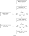
- Fig. 2 shows a flow chart of obstacle recognition and road surface fluctuation recognition in one embodiment of the present application.
- Fig. 3 shows a flow chart for attempting to update a grayscale standard value in one embodiment of the present application.
- the step of determining a target image set from the target video data it further comprises:
- This embodiment provides a method for updating a target image set and a grayscale standard value.
- the second difference reference value of the L frames of images is further calculated.
- the second difference reference value is configured to reflect the overall average difference between the grayscale of all the pixel points in the background area of the continuous L frames of images and the corresponding grayscale standard values.
- the second difference threshold value is configured to define whether there is road surface fluctuation in the background area. For example, the overall color of the road surface in the image changes due to factors such as road surface material or external lighting, or it is possible that there are obstacles in areas outside the obstacle monitoring area.
- the step of aiming at each pixel point of the obstacle monitoring area, taking a grayscale average value of the same pixel point in the target image set as a grayscale standard value of the pixel point it further comprises:
- This embodiment provides another method for updating the target image set and the grayscale standard value. As shown in Fig. 3 , when the update cycle is reached, a trial operation is performed, that is, N consecutive frames of images are obtained to calculate the grayscale change reference value. If the grayscale change reference value meets the requirements, the target image set and the grayscale standard value are updated, otherwise no update is performed. For example, the vehicle attempts to update every 30 minutes of driving.
- the first real-time fluctuation update strategy ensures that the grayscale standard value is updated in time when the road surface changes to a certain extent
- the second periodic update strategy ensures that a certain update frequency can be guaranteed even when the road surface changes slightly, thereby comprehensively improving the reliability of the grayscale standard value and ensuring the accuracy of the obstacle recognition algorithm.
- the embodiment of the present application further provides a driving blind area monitoring apparatus.
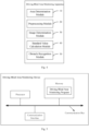
- Fig. 4 shows a functional module diagram of a driving blind area monitoring apparatus in one embodiment of the present application.
- the driving blind area monitoring apparatus comprises:
- the image determination module 30 is configured to:
- the obstacle recognition module 50 is configured to:
- the standard value calculation module 40 is further configured to:
- the driving blind area monitoring apparatus further comprises an update module, which is configured to:
- the driving blind area monitoring apparatus further comprises a camera determination module, which is configured to:
- the background area comprises all drivable areas in the area shot by the target camera, and the obstacle monitoring area is located in the adjacent lane area corresponding to the target camera.
- each module in the driving blind area monitoring apparatus corresponds to the steps in the driving blind area monitoring method in the above embodiment, and the function and implementation process thereof will not be repeated herein.
- the embodiment of the present application provides a driving blind area monitoring device
- the driving blind area monitoring device can be a personal computer (PC), a laptop computer, a server, or other device with data processing capabilities.
- Fig. 5 shows a hardware structure diagram of a driving blind area monitoring device involved in the embodiment of the present application.
- the driving blind area monitoring device can comprise a processor, a memory, a communication interface, and a communication bus.
- the communication bus can be of any type and is configured to interconnect the processor, the memory, and the communication interface.
- the communication interface comprises input/output (I/O) interfaces, physical interfaces, and logical interfaces, etc. These interfaces are configured to realize the interconnection of the components inside the driving blind area monitoring device, and the interconnection between the driving blind area monitoring device and other devices (such as other computing devices or user devices).
- the physical interface can be an Ethernet interface, an optical fiber interface, an ATM interface, etc.
- the user device can be a display, a keyboard, etc.
- the memory can be various types of storage media, such as random-access memory (RAM), read-only memory (ROM), non-volatile RAM (NVRAM), flash memory, optical storage, hard disk, programmable ROM (PROM), and electrically erasable PROM (EEPROM).
- RAM random-access memory
- ROM read-only memory
- NVRAM non-volatile RAM
- EEPROM electrically erasable PROM
- the processor can be a general-purpose processor, which can call the driving blind area monitoring program stored in the memory and execute the driving blind area monitoring method provided in the embodiment of the present application.
- the general-purpose processor can be a central processing unit (CPU).
- CPU central processing unit
- Fig. 5 does not constitute a limitation of the present application, and can comprise more or less components than those shown in Fig. 5 , or combine some components, or arrange different components.
- the embodiment of the present application further provides a storage medium.
- the readable storage medium of the present application stores the driving blind area monitoring program, wherein when the driving blind area monitoring program is executed by a processor, the steps of the above-mentioned driving blind area monitoring method are realized.
Landscapes
- Engineering & Computer Science (AREA)
- Physics & Mathematics (AREA)
- General Physics & Mathematics (AREA)
- Theoretical Computer Science (AREA)
- Multimedia (AREA)
- Computer Vision & Pattern Recognition (AREA)
- Software Systems (AREA)
- Computing Systems (AREA)
- Artificial Intelligence (AREA)
- Databases & Information Systems (AREA)
- Evolutionary Computation (AREA)
- General Health & Medical Sciences (AREA)
- Medical Informatics (AREA)
- Health & Medical Sciences (AREA)
- Computational Linguistics (AREA)
- Mechanical Engineering (AREA)
- Closed-Circuit Television Systems (AREA)
Applications Claiming Priority (2)
| Application Number | Priority Date | Filing Date | Title |
|---|---|---|---|
| CN202311233136.2A CN117315619B (zh) | 2023-09-22 | 2023-09-22 | 行车盲区监测方法、装置、设备及可读存储介质 |
| PCT/CN2024/088761 WO2025060413A1 (zh) | 2023-09-22 | 2024-04-19 | 行车盲区监测方法、装置、设备及可读存储介质 |
Publications (2)
| Publication Number | Publication Date |
|---|---|
| EP4553794A1 true EP4553794A1 (de) | 2025-05-14 |
| EP4553794A4 EP4553794A4 (de) | 2026-01-14 |
Family
ID=89249215
Family Applications (1)
| Application Number | Title | Priority Date | Filing Date |
|---|---|---|---|
| EP24785958.0A Pending EP4553794A4 (de) | 2023-09-22 | 2024-04-19 | Verfahren, vorrichtung und vorrichtung zur überwachung eines fahrblindpunkts und lesbares speichermedium |
Country Status (3)
| Country | Link |
|---|---|
| EP (1) | EP4553794A4 (de) |
| CN (1) | CN117315619B (de) |
| WO (1) | WO2025060413A1 (de) |
Families Citing this family (4)
| Publication number | Priority date | Publication date | Assignee | Title |
|---|---|---|---|---|
| CN117315619B (zh) * | 2023-09-22 | 2024-12-31 | 东风商用车有限公司 | 行车盲区监测方法、装置、设备及可读存储介质 |
| CN119445296B (zh) * | 2024-11-07 | 2025-08-29 | 深圳市小飞达电子有限公司 | 一种基于ai摄像技术的盲区精度评估方法及系统 |
| CN120431141B (zh) * | 2025-07-08 | 2025-09-16 | 龙岩学院 | 一种基于图像融合的半挂车危险源监控方法 |
| CN120740863B (zh) * | 2025-09-01 | 2025-11-21 | 延安大学 | 一种用于天然气泄漏的智能检测装置及方法 |
Family Cites Families (6)
| Publication number | Priority date | Publication date | Assignee | Title |
|---|---|---|---|---|
| KR101122260B1 (ko) * | 2009-12-29 | 2012-03-20 | 주식회사 바텍 | 파노라마 영상 획득 방법 및 장치 |
| JP7104916B2 (ja) * | 2018-08-24 | 2022-07-22 | 国立大学法人岩手大学 | 移動物体検出装置および移動物体検出方法 |
| CN111186432B (zh) * | 2018-11-13 | 2021-05-28 | 杭州海康威视数字技术股份有限公司 | 一种车辆盲区预警的方法及装置 |
| CN113642453A (zh) * | 2021-08-11 | 2021-11-12 | 北京京东乾石科技有限公司 | 障碍物的检测方法、装置和系统 |
| CN116092050B (zh) * | 2022-12-29 | 2025-10-21 | 深圳市豪恩汽车电子装备股份有限公司 | 机动车障碍物检测方法、装置及计算机可读存储介质 |
| CN117315619B (zh) * | 2023-09-22 | 2024-12-31 | 东风商用车有限公司 | 行车盲区监测方法、装置、设备及可读存储介质 |
-
2023
- 2023-09-22 CN CN202311233136.2A patent/CN117315619B/zh active Active
-
2024
- 2024-04-19 WO PCT/CN2024/088761 patent/WO2025060413A1/zh active Pending
- 2024-04-19 EP EP24785958.0A patent/EP4553794A4/de active Pending
Also Published As
| Publication number | Publication date |
|---|---|
| EP4553794A4 (de) | 2026-01-14 |
| CN117315619B (zh) | 2024-12-31 |
| CN117315619A (zh) | 2023-12-29 |
| WO2025060413A1 (zh) | 2025-03-27 |
Similar Documents
| Publication | Publication Date | Title |
|---|---|---|
| EP4553794A1 (de) | Verfahren, vorrichtung und vorrichtung zur überwachung eines fahrblindpunkts und lesbares speichermedium | |
| CN110889351B (zh) | 视频检测方法、装置、终端设备及可读存储介质 | |
| KR101163446B1 (ko) | 가상 차선을 이용하는 차선 이탈 경보 방법 및 그에 따른 시스템 | |
| CN113139482A (zh) | 交通异常检测的方法和装置 | |
| US8457408B2 (en) | Method and system of identifying one or more features represented in a plurality of sensor acquired data sets | |
| US20190251372A1 (en) | System and method for lane detection | |
| JP2001357484A (ja) | 道路異常検出装置 | |
| US20220148316A1 (en) | Method and device for determining road operation condition, and storage medium | |
| CN113076851B (zh) | 一种车辆违章数据的采集方法、装置以及计算机设备 | |
| CN111428644A (zh) | 基于深度神经网络的斑马线区域监测方法、系统及介质 | |
| CN107346547B (zh) | 基于单目平台的实时前景提取方法及装置 | |
| CN108162858A (zh) | 车载监控装置及其方法 | |
| CN114898325A (zh) | 一种车辆危险变道检测方法、装置及电子设备 | |
| CN113255612A (zh) | 前车起步提醒方法及系统、电子设备和存储介质 | |
| US12403936B2 (en) | Method for controlling a driver assistance system during operation of a vehicle | |
| RU2853014C1 (ru) | Способ, аппарат, устройство и считываемый носитель для хранения данных для отслеживания слепой зоны при вождении | |
| CN119785162A (zh) | 一种基于多模型融合提升事件检测正确率的方法 | |
| US20240212196A1 (en) | Methods and devices for setting a threshold in an object detection system | |
| KR100383538B1 (ko) | 차선이탈 경보 방법 및 시스템 | |
| CN110556024B (zh) | 一种防碰撞辅助驾驶方法、系统及计算机可读存储介质 | |
| CN106128105A (zh) | 一种交通路口行人行为监测系统 | |
| CN118991606A (zh) | 一种盲区碰撞预警方法和系统 | |
| JPH08320998A (ja) | レーンマーカ検出装置 | |
| CN111091096B (zh) | 车辆偏离决策方法、装置、存储介质及车辆 | |
| CN118506321A (zh) | Bsd摄像头偏移预警方法、装置及电子设备 |
Legal Events
| Date | Code | Title | Description |
|---|---|---|---|
| STAA | Information on the status of an ep patent application or granted ep patent |
Free format text: STATUS: UNKNOWN |
|
| STAA | Information on the status of an ep patent application or granted ep patent |
Free format text: STATUS: THE INTERNATIONAL PUBLICATION HAS BEEN MADE |
|
| PUAI | Public reference made under article 153(3) epc to a published international application that has entered the european phase |
Free format text: ORIGINAL CODE: 0009012 |
|
| STAA | Information on the status of an ep patent application or granted ep patent |
Free format text: STATUS: REQUEST FOR EXAMINATION WAS MADE |
|
| 17P | Request for examination filed |
Effective date: 20241014 |
|
| AK | Designated contracting states |
Kind code of ref document: A1 Designated state(s): AL AT BE BG CH CY CZ DE DK EE ES FI FR GB GR HR HU IE IS IT LI LT LU LV MC ME MK MT NL NO PL PT RO RS SE SI SK SM TR |
|
| A4 | Supplementary search report drawn up and despatched |
Effective date: 20251215 |
|
| RIC1 | Information provided on ipc code assigned before grant |
Ipc: G06V 20/58 20220101AFI20251209BHEP Ipc: G06V 20/40 20220101ALI20251209BHEP Ipc: G06V 10/764 20220101ALI20251209BHEP Ipc: G06T 7/254 20170101ALI20251209BHEP Ipc: G06T 7/73 20170101ALI20251209BHEP |