EP4553802A1 - Dispositifs de surveillance personnels portables et systèmes associés - Google Patents
Dispositifs de surveillance personnels portables et systèmes associés Download PDFInfo
- Publication number
- EP4553802A1 EP4553802A1 EP23383141.1A EP23383141A EP4553802A1 EP 4553802 A1 EP4553802 A1 EP 4553802A1 EP 23383141 A EP23383141 A EP 23383141A EP 4553802 A1 EP4553802 A1 EP 4553802A1
- Authority
- EP
- European Patent Office
- Prior art keywords
- sos
- home
- event
- remote monitoring
- transmitter
- Prior art date
- Legal status (The legal status is an assumption and is not a legal conclusion. Google has not performed a legal analysis and makes no representation as to the accuracy of the status listed.)
- Withdrawn
Links
Images



Classifications
-
- G—PHYSICS
- G08—SIGNALLING
- G08B—SIGNALLING SYSTEMS, e.g. PERSONAL CALLING SYSTEMS; ORDER TELEGRAPHS; ALARM SYSTEMS
- G08B21/00—Alarms responsive to a single specified undesired or abnormal condition and not otherwise provided for
- G08B21/02—Alarms for ensuring the safety of persons
- G08B21/04—Alarms for ensuring the safety of persons responsive to non-activity, e.g. of elderly persons
- G08B21/0438—Sensor means for detecting
- G08B21/0446—Sensor means for detecting worn on the body to detect changes of posture, e.g. a fall, inclination, acceleration, gait
-
- G—PHYSICS
- G08—SIGNALLING
- G08B—SIGNALLING SYSTEMS, e.g. PERSONAL CALLING SYSTEMS; ORDER TELEGRAPHS; ALARM SYSTEMS
- G08B21/00—Alarms responsive to a single specified undesired or abnormal condition and not otherwise provided for
- G08B21/02—Alarms for ensuring the safety of persons
- G08B21/04—Alarms for ensuring the safety of persons responsive to non-activity, e.g. of elderly persons
- G08B21/0407—Alarms for ensuring the safety of persons responsive to non-activity, e.g. of elderly persons based on behaviour analysis
- G08B21/043—Alarms for ensuring the safety of persons responsive to non-activity, e.g. of elderly persons based on behaviour analysis detecting an emergency event, e.g. a fall
-
- G—PHYSICS
- G08—SIGNALLING
- G08B—SIGNALLING SYSTEMS, e.g. PERSONAL CALLING SYSTEMS; ORDER TELEGRAPHS; ALARM SYSTEMS
- G08B25/00—Alarm systems in which the location of the alarm condition is signalled to a central station, e.g. fire or police telegraphic systems
- G08B25/01—Alarm systems in which the location of the alarm condition is signalled to a central station, e.g. fire or police telegraphic systems characterised by the transmission medium
- G08B25/016—Personal emergency signalling and security systems
-
- G—PHYSICS
- G08—SIGNALLING
- G08B—SIGNALLING SYSTEMS, e.g. PERSONAL CALLING SYSTEMS; ORDER TELEGRAPHS; ALARM SYSTEMS
- G08B21/00—Alarms responsive to a single specified undesired or abnormal condition and not otherwise provided for
- G08B21/02—Alarms for ensuring the safety of persons
- G08B21/04—Alarms for ensuring the safety of persons responsive to non-activity, e.g. of elderly persons
- G08B21/0438—Sensor means for detecting
- G08B21/0453—Sensor means for detecting worn on the body to detect health condition by physiological monitoring, e.g. electrocardiogram, temperature, breathing
-
- G—PHYSICS
- G08—SIGNALLING
- G08B—SIGNALLING SYSTEMS, e.g. PERSONAL CALLING SYSTEMS; ORDER TELEGRAPHS; ALARM SYSTEMS
- G08B25/00—Alarm systems in which the location of the alarm condition is signalled to a central station, e.g. fire or police telegraphic systems
- G08B25/007—Details of data content structure of message packets; data protocols
-
- G—PHYSICS
- G08—SIGNALLING
- G08B—SIGNALLING SYSTEMS, e.g. PERSONAL CALLING SYSTEMS; ORDER TELEGRAPHS; ALARM SYSTEMS
- G08B29/00—Checking or monitoring of signalling or alarm systems; Prevention or correction of operating errors, e.g. preventing unauthorised operation
- G08B29/18—Prevention or correction of operating errors
- G08B29/181—Prevention or correction of operating errors due to failing power supply
Definitions
- the present invention relates to wearable personal monitoring devices and to systems that work with or support such devices.
- WHO World Health Organization
- Such devices may also include, or be worn in combination with, a fall detector which may raise an alarm or summon assistance automatically in the event that someone wearing the device experiences a fall.
- Such devices often come in the form of a large pendant that hangs from a cord around the wearer's neck, although it is also known to provide a wrist-mounted device that may be worn in the manner of a wristwatch and that may, for convenience, also function as a watch.
- the device is in the form of a wristwatch with a strap-mounted body having a face and hands to display the time.
- the case carries an actuator (or pusher), in the form of a push button. Operation of the actuator, typically pushing it radially inwards, results in the device signalling an SOS or alarm condition.
- This may involve simply using an internal sounder that produces a loud audible alarm, but more typically results in the device transmitting wirelessly (typically over a relatively short range connection, such as a low power 868MHz ISM channel, to an in-home support unit that can then forward alarm messages to a remote monitoring centre, typically over a broadband connection) an alarm signal for reception at a remote monitoring device or service.
- the actuator for signalling an SOS only has a single function, to reduce the risk of inadvertently signalling an SOS or alarm event.
- a crown wheel may, as shown, be provided to enable the hands of the watch display to be adjusted, and optionally other adjustments and inputs made.
- Apple Corporation's Apple Watch has a battery life of up to 18 hours, meaning that it must be recharged every day if it is to keep functioning, and the watch must be removed from the wearer every day to enable charging.
- a wearable SOS device would preferably have a much longer battery life - preferably of several days or even as much as a week, so that occurrences of "down time" when the device cannot be worn - and hence cannot provide fall detection and SOS cover - can be minimised. There is also the risk that the wearer of the SOS device may neglect to charge the device, with consequent risk of loss of all functionality.
- a personal wearable monitoring device including an SOS button, a processor and, operatively coupled to the processor, an accelerometer, at least one RF transmitter, the processor being programmed to activate the at least one RF transmitter to transmit an alert message in the event that either an SOS event is signalled via the SOS button or signals received from the accelerometer indicate a fall, wherein the device is configured to determine whether it is in range of a dedicated home node, and if the device determines that it is out of range the device is configured periodically to report its position to a remote monitoring station using the at least one RF transmitter.
- the device may be configured periodically to report its presence to a dedicated home node (which may also be referred to as an in-home support unit) using the at least one RF transmitter, preferably using a different transmission mode (e.g. at least one of a different power, frequency, modulation type, etc.) to that used to communicate with the remote monitoring station to provide a short range communication mode that is receivable by the home node but not by the remote monitoring station
- a dedicated home node which may also be referred to as an in-home support unit
- a different transmission mode e.g. at least one of a different power, frequency, modulation type, etc.
- Use of a low power communication may significantly reduce drain of the device's battery and may also support compliance with power usage restrictions that apply to some ISM (or equivalent) bands in some jurisdictions. For example, using a transmitter transmitting using a permissible ISM band, such as an 868 MHz channel (or equivalent, as appropriate, outside Europe) with a low power transmission mode.
- a permissible ISM band such as an 868 MHz channel (or equivalent, as appropriate, outside Europe) with a low power transmission mode.
- the device may be configured to shut down its at least one RF transmitter (e.g. transceiver) between reporting instances, and may further be configured to wait before shutting down its (e.g. all or some of its) at least one RF transmitter, for a predetermined period after each reporting instance, to receive a communication from the remote monitoring station.
- a device may further be configured to continue to power its (or one or more of its) RF transmitter(s) upon receiving an appropriate request from the remote monitoring station.
- the device may be configured to provide a step count function, and optionally periodically to report a step count, and such a device may further be configured to adapt the periodicity of position reporting based on information from the step counting function. Such a device may further be configured to increase the frequency of position reporting after a threshold number of steps have been counted.
- a personal wearable monitoring device including an SOS button, a processor and, operatively coupled to the processor, an accelerometer, at least one RF transmitter, the processor being programmed to activate the at least one RF transmitter to transmit an alert message in the event that either an SOS event is signalled via the SOS button or signals received from the accelerometer indicate a fall, wherein: the device is configured to determine whether it is in range of a dedicated home node, and if the device determines that it is out of range the device is configured periodically to report its position to a remote monitoring station using the at least one RF transmitter; and the device being further configured to adapt the periodicity of position reporting based on information from a step counting function.
- the at least one RF transmitter may be a single transmitter that can be configured (e.g. tuned and adapted) on the one hand to provide short range communication (preferably with low power consumption) for communication with an in-home support unit, and on the other to provide long range communication (also preferably with low power consumption) for communication with a remote monitoring centre when out of range of the in-home support unit (e.g. when away from home).
- the at least one RF transmitter may be plural transmitters (e.g. plural transceivers) to provide at least the just-described functionality - for example one dedicated transmitter (e.g.
- the device may determine that it is "at home” by transmitting a short range signal (e.g. using a transceiver that it uses to communicate with the in-home support unit, e.g. a low power 868 MHz channel) to "ping" the central unit: if the device receives an answer from the in-home support unit the device determines that it is "at home”
- a short range signal e.g. using a transceiver that it uses to communicate with the in-home support unit, e.g. a low power 868 MHz channel
- the device may be arranged to capture, and optionally store, an audio clip in the event that the device detects a fall or in the event that an SOS event is reported via the SOS button.
- Such a device may further be configured to transmit the captured audio clip to the remote monitoring station either: along with reporting a fall or an SOS event to the remote monitoring station; or upon receiving a request to transmit the audio clip.
- Such a device may further be configured to capture a further sound clip upon a request so to do received from the remote monitoring station.
- the device may further comprise a GNSS receiver (for example in addition to the at least one transceivers previously mentioned), and the device may be configured to shut down the GNSS for extended periods between reporting instances.
- a GNSS receiver for example in addition to the at least one transceivers previously mentioned
- Such a device may further be configured to determine device velocity (in particular a lateral or non-vertical velocity) and to increase the rate of reporting position to the remote monitoring centre in the event that the determined device velocity exceeds a predetermined threshold.
- the device may be configured to apply a fall detection algorithm to identify fall events, and the device may have an operating mode in which sensitivity of detecting fall events is greater when the device is "at home” than when the device is "away from home”.
- the device may have an operating mode in which it is configured to detect Wi-Fi network identities and Wi-Fi network signal strengths, but in which it is not configured to transmit data in the form of Wi-Fi signals.
- Such a device may have an operating mode in which it is configured to determine that it is at a home location based on stored Wi-Fi network identities and Wi-Fi network signal strengths corresponding to the home location.
- the device may be a wrist-worn device, and optionally may comprise a timepiece.
- the device may further comprise a haptic transducer, the processor optionally being programmed to activate the haptic transducer to provide user feedback in the event that an SOS event is signalled.
- the at least one RF transmitter may include a transmitter configured to operate on a low power wide area cellular network such as LTE Cat M and NB IoT (e.g. for communication with the remote monitoring centre).
- a low power wide area cellular network such as LTE Cat M and NB IoT (e.g. for communication with the remote monitoring centre).
- the at least one RF transmitter may include a transmitter configured to operate on an unlicensed frequency band such as an ISM band (e.g. for communication with the in-home support unit).
- an ISM band e.g. for communication with the in-home support unit.
- the processor may be further programmed to transmit the device location when signalling an SOS event.
- the processor may be further programmed to provide feedback to the wearer (e.g. through the display in the face of the watch) in the event that signals received from the accelerometer indicate a fall, to enable the wearer to cancel the alert message in the event that no intervention or assistance is required.
- the processor may be further programmed to provide feedback to the wearer (e.g. through a display in the face of the watch, or through vibration or the like) on receiving confirmation of successful delivery of an alert message.
- the device may further comprise a microphone, the processor optionally being further programmed to: (i) record an audio clip from the microphone, optionally in response to an SOS event, and/or (ii) couple the microphone of the device to a remote entity for verification and monitoring (e.g. to enable an appropriate response to be provided).
- the processor optionally being further programmed to: (i) record an audio clip from the microphone, optionally in response to an SOS event, and/or (ii) couple the microphone of the device to a remote entity for verification and monitoring (e.g. to enable an appropriate response to be provided).
- the accelerometer may be a 3-axis accelerometer.
- the monitoring device may also be a safety device.
- a security monitoring system for premises the system being of the kind that, in an armed state, is operable to report security breaches, such as the opening of a door or window, detected by a door/window sensor, to a remote monitoring station, the system being configured to: receive alert messages from a device at the premises, the device being according to any variant of the first or second aspect; forward received alert messages to the remote monitoring station; action any request received from the remote monitoring station for access to a microphone on the device by transmitting an appropriate instruction to the device; and thereafter forwarding to the remote monitoring station signals received from the device.
- the device may be configured to function as a token to arm and to disarm the security monitoring system.
- a system comprising a device according to any variant of the first or second aspect and a base station/home hub/central unit with which the device is capable of communicating using a short range RF communication mode.
- the home hub may be a central unit for a security monitoring system for premises.
- the home hub may be configured to perform Wi-Fi sensing within the premises, and further configured to perform at least one of the following: use data from Wi-Fi sensing in conjunction with data from the device to confirm fall events reported by the device; supply Wi-Fi sensing data to a back end/monitoring station to enable the back end/monitoring station to confirm fall events reported by the device.
- the home hub may be configured, in response to receiving an alert sent by the device, to push notifications to an associated user device (carer's device).
- the home hub may be configured, in response to receiving an alert sent by the device, to instruct the device to keep open a communications channel (with the home hub).
- the home hub may be configured, in response to receiving an alert sent by the device, to instruct the device to send an audio capture to the home hub.
- any variant of the fourth aspect may further comprise a system backend or a remote monitoring station.
- the home hub may be arranged to forward to the device requests/commands received from the system backend or a remote monitoring station.
- the home hub may also be configured to send notifications to the remote monitoring centre/system back end.
- the system back end may be arranged to push notifications, based on notification received from the device, e.g. to a user WTRU device.
- a backend entity of a system that provides personal monitoring services by means of a wearable personal monitoring device comprising:
- the notification received from the monitoring device may signify an SOS event or a fall.
- the notification received from the monitoring device may include location information or information enabling the location of the device to be determined.
- the notification may include information indicating that the monitoring device is away from a home location of the device.
- the notification may include an audio clip captured by the device.
- the notification may include a report of a step count determined by the device
- Any method according to the fifth aspect may further comprise causing transmission of a carer/user notification to a user device, content of the carer/user notification depending upon the type or content of the notification received from the monitoring device, for example from the backend entity or from another entity upon request by the backend entity or by the system that provides personal monitoring services.
- the SOS button may include a visual indicator to indicate the extent to which the button needs to be depressed to signal an SOS event.
- first or second aspect may further comprise a push button crown element, the crown element having a configuration including at least one selected from:
- the front face of the device may be configured as a watch face to display the time using at least a pair of hands.
- devices may have a mechanical drive for watch hands, optionally including a stepper motor.
- the face of the device may further comprise an optoelectronic display arrangement.
- watch hands could be displayed on an optoelectronic display arrangement.
- the SOS button may be arranged to activate a mechanical switch or an electronic switch.
- An electronic switch may have a total travel of less than half a millimetre, yet it may improve the ergonomics of the device if the SOS button requires longer travel (perhaps twice the travel of the switch, for example 1 to 1.2mm) in order to enter an SOS alert.
- the user when the SOS button is activated, the user may be given an option to cancel - for example by holding on top of the "crystal" over the display.
- the device may be configured to activate the display to provide visual feedback/announcement of detected activation of the SOS switch, or the cancellation of an alert. Additionally or alternatively, the device may provide a haptic feedback signal (e.g. in the form of a vibration or buzz).
- a haptic feedback signal e.g. in the form of a vibration or buzz.
- a personal wearable monitoring device including an SOS button, a processor and, operatively coupled to the processor, an accelerometer, at least one RF transmitter, the processor being programmed to activate the at least one RF transmitter to transmit an alert message in the event that either an SOS event is signalled via the SOS button or signals received from the accelerometer indicate a fall, wherein the device is configured to determine whether it is in range of a dedicated home node, and to switch between (i) a first operating mode when the device is in range; and (ii) a second operating mode when the device is out of range.
- the first and second operating modes may include at least some functionality in common, but with different parameters.
- the first and second operating modes may both comprise detecting occurrence of falls, but with different sensitivities of fall detection.
- the sensitivity of fall detection may be higher than in the second operating mode. This may be especially useful when the home node is configured to directly or indirectly detect or infer fall detection by other means, such as by radio-signal based fall detection, or by processing one or more images from one or more cameras.
- the home node may verify falls detected by the wearable device, thereby reducing the risk of false positive alarms, even though the wearable device is more sensitive to falls in the first operating mode than in the second operating mode.
- At least the second operating mode may comprise the device periodically reporting its position to a remote monitoring station using the at least one RF transmitter, as explained earlier.
- the first operating mode may optionally comprise not reporting position, or reporting position less frequently than in the second operating mode.
- the first operating mode may comprise transmitting commands for controlling the activation state of an alarm and/or an electronically controlled lock at a premises.
- a seventh aspect there is provided a method of operating a personal wearable monitoring device that includes an SOS button, a processor and, operatively coupled to the processor, an accelerometer, and at least one RF transmitter, the method comprising: activating the at least one RF transmitter to transmit an alert message in the event that either an SOS event is signalled via the SOS button or signals received from the accelerometer indicate a fall; determining whether the device is in range of a dedicated home node; and switching between
- the first and second operating modes may include at least some functionality in common, but with different parameters.
- the first and second operating modes may both comprise detecting occurrence of falls, but with different sensitivities of fall detection.
- the sensitivity of fall detection may be higher than in the second operating mode. This may be especially useful when the home node is configured to directly or indirectly detect or infer fall detection by other means, such as by radio-signal based fall detection, or by processing one or more images from one or more cameras.
- the home node may verify falls detected by the wearable device, thereby reducing the risk of false positive alarms, even though the wearable device is more sensitive to falls in the first operating mode than in the second operating mode.
- At least the second operating mode may comprise the device periodically reporting its position to a remote monitoring station using the at least one RF transmitter, as explained earlier.
- the first operating mode may optionally comprise not reporting position, or reporting position less frequently than in the second operating mode.
- the first operating mode may comprise transmitting commands for controlling the activation state of an alarm and/or an electronically controlled lock at a premises.
- a security monitoring system for premises the system being of the kind that, in an armed state, is operable to report security breaches, such as the opening of a door or window, detected by a door/window sensor, to a remote monitoring station, the system being configured to:
- the first and second operating modes may include at least some functionality in common, but with different parameters.
- the first and second operating modes may both comprise detecting occurrence of falls, but with different sensitivities of fall detection.
- the sensitivity of fall detection may be higher than in the second operating mode. This may be especially useful when the home node is configured to directly or indirectly detect or infer fall detection by other means, such as by radio-signal based fall detection, or by processing one or more images from one or more cameras.
- the home node may verify falls detected by the wearable device, thereby reducing the risk of false positive alarms, even though the wearable device is more sensitive to falls in the first operating mode than in the second operating mode.
- At least the second operating mode may comprise the device periodically reporting its position to a remote monitoring station using the at least one RF transmitter, as explained earlier.
- the first operating mode may optionally comprise not reporting position, or reporting position less frequently than in the second operating mode.
- the first operating mode may comprise transmitting commands for controlling the activation state of an alarm and/or an electronically controlled lock at a premises.
- FIG 1 is a schematic plan view of a wrist-worn monitoring or SOS device 100 according to aspects of the invention.
- the device includes a case 102, typically of metal or of an engineering plastic, having a display 104, here in the form of a watch face including hands, although watch functionality is optional.
- the hands if present, are preferably physical elements coupled to a drive mechanism (for example one including a stepper motor), but in other embodiments the hands, if provided, may be "virtual" and provided instead by display technology such as AMOLED (active-matrix organic light emitting diode), liquid crystal (optionally TFT LCD, or transreflective).
- AMOLED active-matrix organic light emitting diode
- liquid crystal optionally TFT LCD, or transreflective
- the case 102 may also include features 103 and 103' by means of which the case can be secured to a strap, bracelet, or band.
- the strap, bracelet, or band may be demountable (as here), or may be formed integrally with the case 102.
- the strap, wrist band or bracelet may provide a convenient location for one or more antennas of the device 100, with the or each antenna being electrically coupled to a respective transmitter and/or receiver (optionally in the form of a transceiver). Different sizes of strap, wrist band, or bracelet may be provided to enable the device to be adapted to wearers having wrists of different circumferences (more generally, sizes). It may also be appropriate to provide more than one size of device to suit people of different builds.
- the display 104 may include hands 106 to indicate the time.
- a crown or crown wheel 108 may be provided, e.g. at the 3 o'clock position, to enable the hands 106 to be adjusted to reset the watch to display the correct time.
- the crown 108 may need to be pulled away from the rest position shown (e.g. in this case to the right), and thereafter the crown 108 may be rotated to adjust the setting of the hands.
- the crown 108 may have at least two withdrawn positions away from the rest position, one for each of the hour and minute hands 106.
- the hands are physical elements coupled to a drive mechanism.
- the crown element 108 could be configured as a means to perform adjustment of the position of the hands, e.g., to correct for any discrepancy in the time displayed, but in the example shown the crown acts simply as a push button and does not rotate.
- the position (setting) of the watch hands may be adjusted using an associated app, for example installed on a user device such as a smartphone.
- the crown element 108 which may be non-rotary, may be used to adjust device settings and/or to select between options.
- an SOS button 101 is provided on the opposite side, at the 9 o'clock position. This may be a push button that needs to be depressed (pushed radially inwards) to activate the device's SOS function.
- the face 104 of the device 100 may include an inset display portion 109 which may be used to provide user feedback (e.g., of the activation of the SOS button 110, the transmission of an SOS message, or of the option selected using the crown), incoming messages - such as from an alarm monitoring station, selectable options, etc.
- the case 102 includes a front face 102a (e.g. facing away from the user's skin surface), a rear face 102b (e.g. facing towards the skin surface of the user), and a peripheral wall 102c extending between the front and rear faces.
- the crown element 108 may have a configuration including at least one selected from: a push-button mushroom configuration; and a push button peripheral surface that is neither knurled nor ridged.
- a mushroom configuration is used herein to mean that the crown itself, or its mounting, includes a neck region between the watch case and the outer region of the crown.
- Devices may include a capacitive "touch” sensor, for example behind the face of the device, to enable user input by "touch”.
- the device may be configured (e.g. the processor suitably programmed) to accept a user putting a thumb, finger, or fingers over the "glass” over the face, as an input - such as an input to cancel an SOS alert or to indicate that no intervention is required following a fall.
- FIG. 2a is a corresponding schematic plan view of another wrist-worn monitoring or SOS device 200 according to aspects of the invention.
- the device 200 comprises a case 202, typically of metal or of an engineering plastic, having a display 204, here in the form of a watch face including hands (not shown explicitly), although watch functionality is optional.
- the hands if present, are preferably physical elements coupled to a drive mechanism (for example one including a stepper motor), but in other embodiments the hands, if provided, may be "virtual" and provided instead by display technology such as AMOLED (active-matrix organic light emitting diode), liquid crystal (optionally TFT LCD, or transreflective).
- the hands are physical elements coupled to a drive mechanism.
- a crown element 208 could be configured as a means to perform adjustment of the position of the hands, e.g., to correct for any discrepancy in the time displayed, but in the example shown the crown acts simply as a push button and does not rotate.
- the position (setting) of the watch hands (if provided) may be adjusted using an associated app, for example installed on a user device such as a smartphone.
- a crown element 208 which may be non-rotary, may be used to adjust device settings and/or to select between options.
- the face 204 of the device 200 may include an inset display portion 209 which may be used to provide user feedback (e.g., of the activation of the SOS button 210, the transmission of an SOS message, or of the option selected using the crown), incoming messages - such as from an alarm monitoring station, selectable options, etc.
- user feedback e.g., of the activation of the SOS button 210, the transmission of an SOS message, or of the option selected using the crown
- incoming messages - such as from an alarm monitoring station, selectable options, etc.
- the case 202 includes a front face 202a (e.g. facing away from the skin surface), a rear face 202b (e.g. facing towards the skin surface), and a peripheral wall 202c extending between the front and rear faces.
- device 200 may include features 203 and 203' by means of which the case 202 can be secured to a strap, wrist band, or bracelet.
- the strap, wrist band or bracelet may be demountable, or may be formed integrally with the case 202.
- the strap, wrist band or bracelet provides a convenient location for one or more antennas of the device 200, the or each antenna being electrically coupled to a respective transmitter and/or receiver (optionally in the form of a transceiver).
- Different sizes of strap, wrist band, or bracelet may be provided to enable the device to be adapted to wearers having wrists of different circumferences (more generally, sizes). It may also be appropriate to provide more than one size of device to suit people of different builds.
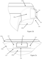
- a guard structure 214 may be provided for shielding, in a direction dependent manner, the SOS button 210 protruding from the peripheral wall. Details of the guard structure are shown in Figures 2b to 2e .
- the guard structure 214 may include the features labelled 212, one either side of the SOS button 210, to protect the SOS button. These features 212, which can be considered to be flanges or fairings, are intended to reduce the incidence of false alarms by making unintentional depression of the SOS button less likely, are arranged one on either side of the SOS button 210.
- the fairings may be configured with a height (depth into the figure in Figure 2 ) that is the same as, slightly more than or slightly less than the corresponding height of the SOS button 210.
- the sides of the SOS button that lie adjacent to the fairings 212 may be parallel or substantially parallel with one another. The inner faces of the pair of flanges 212 may abut against respective side faces of the SOS button 210.
- the opposed inner faces of the fairings, between which the SOS button is received may be separated by, for example, between 9 and 15 millimetres, for example between 10 and 13mm.
- the guard structure substantially conceals sides of the SOS button on at least first and second opposite sides with respect to the peripheral wall.
- the guard structure includes a pair of lateral flanges, one to either side of the SOS button for shielding side faces the SOS button that protrude from the peripheral wall, optionally substantially the entirety of the side faces of the SOS button that protrude from the peripheral wall.
- the guard structure may include a pair of lateral flanges 212, one to either side of the SOS button 210 for shielding side faces the SOS button 210 that protrude from the peripheral wall, optionally substantially the entirety of the side faces of the SOS button 210 that protrude from the peripheral wall.
- the guard structure can further comprise an element (floor) 216 that extends to the rear (e.g. beneath when viewed from above as in Figure 2 ) the SOS button 210.
- the flanges 212 and the floor 216 may cooperate to provide an enhanced guard structure 214 that largely protects the button from inadvertent activation.
- the guard structure 214 may include a floor 216 extending between the lateral flanges 212 to the rear of the SOS button, the guard structure shielding on three sides substantially the entire length of that part of the SOS button that protrudes from the peripheral wall.
- the lateral flanges 212 and the floor 216 may each extend outwards from the peripheral wall to substantially the same extent.
- the guard structure 214 may be fixed with respect to the peripheral wall.
- the pair of fairings 212 and the floor may be formed integrally to form a robust structure that largely surrounds three sides of the SOS button 210. Together, the fairings 212 and the floor cooperate to leave the SOS button 210 accessible but not exposed.
- the guard structure shields the SOS button 210 to the rear, without shielding, or shielding to a lesser extent, the SOS button 210 at the front.
- the guard structure substantially conceals the SOS button 210 at least to the rear.
- the guard structure 214 includes the floor 216 extending adjacent to the rear of the SOS button 210 for shielding a rear of the SOS button 210 that protrudes from the peripheral wall, optionally substantially the entirety of the rear of the SOS button 210 that protrudes from the peripheral wall.
- the guard structure is formed integrally with the peripheral wall.
- the SOS button includes a visual indicator (represented by black line 218 in Fig. 2 ) to indicate at least partly an extent to which the button needs to be depressed to signal an SOS event.
- the indicator is provided as a band that contrasts visibly with respect to the rest of the SOS button - the contrast may be in colour, for example a red band on a black, white, silver, or gold button. Or, the contrast may be in hue or brightness with respect to the rest of the button.
- the visual indicator may be provided at the root or base of the button - so that signalling of an SOS event involves depressing the SOS button sufficiently to conceal at least a portion, optionally a majority and optionally all, of the visual indicator.
- the crown element 208 may have a configuration including at least one selected from: a push-button mushroom configuration; and a push button peripheral surface that is neither knurled nor ridged.
- a mushroom configuration is used herein to mean that the crown itself, or its mounting, includes a neck region between the watch case and the outer region of the crown.
- SOS devices may include a capacitive "touch" sensor, for example behind the face of the device, to enable user input by "touch”.
- the device may be configured (e.g. the processor suitably programmed) to accept a user putting a thumb, finger, or fingers over the "glass” over the face, as an input - such as an input to cancel an SOS alert or to indicate that no intervention is required following a fall.
- FIG 3 is a schematic showing the main functional units that may constitute a device 300 (which may be in the form shown in Figure 1 or 2 , or in another form) according to aspects of the invention.
- a processor 302 which may for example be a micro-controller (MCU), to which the other functional units are operatively coupled.
- the processor is supported by a memory 303 (although if the processor is an MCU, the memory may be internal to the MCU).
- the processor 302 and other electronics of the device 300 are powered by a rechargeable battery arrangement 304.
- the device 300 may also include a charging arrangement 305, coupled to the battery 304, to enable the battery to be charged without removal from the device 300, e.g. via inductive charging or via suitable located electrical contacts by means of which the device may be coupled to an external charging arrangement.
- a display module 306 may comprise, as shown, an electronic display component 307 such as the unit 109/209 of Figure 1 / 2 , and a mechanical display arrangement 308 which may include a mechanical drive mechanism, such as a stepper motor, coupled to hands of a watch display. But in other embodiments the mechanical display arrangement 308 may be dispensed with, so that the display module 306 may comprise just an electronic display component (or more than one such component): for example, the whole of the face (e.g., 104/204) of a monitoring device may be in the form of a display based on appropriate display technology (e.g., AMOLED or liquid crystal).
- An RF module 310 includes one or more RF transmitters and receivers 312, 314, which may be in the form of transceivers, to cover one or more wavelength band and communication protocol - for example to cover SOS communication outdoors (where the in-home support unit may not be accessible) using a long-range protocol such a Sigfox or LoRaWAN (both low power, long range WANs).
- a long-range protocol such as a Sigfox or LoRaWAN (both low power, long range WANs).
- 3GPP 3GPP
- the RF module may optionally include a transceiver capable of supporting Wi-Fi, although in general the high power consumption of Wi-Fi makes it less attractive as a communication mode.
- Wi-Fi is the fact that base stations transmit the Wi-Fi network's SSID, and hence by providing the device with the capability to receive Wi-Fi signals and read SSIDs the device may be able to determine its location - or at least the fact that the Wi-Fi landscape corresponds to a known environment (e.g. when the device is "at home” it sees a particular combination of SSIDs from the home AP and from APs in neighbouring premises).
- the device may be able to determine that it is "at home” just by considering which SSIDs can be seen, and possibly by considering their (relative) signal strengths (RSSI).
- RSSI signal strengths
- the RF module 310 may be coupled to one or more appropriate RF antennas 316, and one or more of these antennas may be located in the strap or wrist band, rather than in the case of the device, in order to optimise antenna performance and hence range/transmission speed.
- An accelerometer 318 which may be a 3-axis device (although simpler devices, such as 2-axis accelerometers, may be used), may be provided for fall/shock detection. By using a 3-axis accelerometer, detection of falls (during which acceleration due to gravity may fall to near zero on an axis that was previously detecting an acceleration of 9.8 m/s 2 ).
- the device 300 may also include a gyroscope 319 to provide information on turns (changes of direction) and rotational movement.
- Such information may be used by the processor 302, in conjunction with information from the accelerometer (such as information on step count, and on ascents and/or descents) to determine whether the device is still at home (i.e. within the confines of a known home, residence, or premises- which may include a garden, or close to the periphery of the property - as the short range signals used by the central unit or base station are likely to propagate beyond the strict confines of the property or premises, for example into the street).
- the device may be configured to learn characteristics of the wearer's movements and also to deduce characteristics of movement that represent activity at home and that that represent leaving home (indicating that the device is no longer "at home").
- the device may learn that the dimensions of the home are such that journeys with more than a certain number of steps (e.g. 20, 25, 30) without a change of direction are not possible within the confines of the home, or that descending or ascending stairs is indicative of leaving the home.
- This approach can be used to trigger the activation of the navigation module, either when it is determined that the device is no longer "at home” or after a certain threshold number of steps or after a certain delay.
- the device may be configured to wake the RF transceiver used for communication with a home base station or central unit (support unit), and to "ping" the base station to see whether a reply is received from the base station.
- the absence of a reply may be taken as evidence that the device is no longer "at home” - and this determination may be used as a trigger for the device to activate a navigation module 328. Having activated the navigation module 328, the device may be configured to determine its location and to report this to a remote monitoring station, as will be described later.
- the processor preferably has at least one operating mode in which, in the event that signals from the accelerometer indicate a fall, the device transmits a "fall alert" signal to the remote monitoring function.
- the processor is preferably programmed to distinguish between "hard” falls (indicative of sudden impact, possibly against an unyielding surface) and “soft” falls (indicative of lesser impacts with less abrupt transitions, possibly through falling onto a yielding surface such as a bed or upholstered furniture, and/or a fall that is broken by interaction with something on the way down).
- the processor may operate according to an algorithm that only reacts to "hard” falls. In the case of soft falls, the wearer may use the SOS button to summon assistance if required.
- the remote monitoring function (or personnel therein, or a relative or carer if the alert is sent to a relevant smartphone or other WTRU user device) may send a signal to the device 300 to cause the processor 302 to open an audio channel to a microphone 320 in an audio module 322.
- the remote monitoring function may be able to verify what has happened ("audio verification") and therefore determine how best to respond. If intervention appears to be required, the remote monitoring function may contact emergency/support services, or relatives/friends of the device wearer - and optionally send a message for display on the device to indicate that help is on its way.
- the processor 302 may be further programmed to record an audio clip from the microphone 320, optionally in response to an SOS event or fall, and/or couple the microphone 320 of the device to a remote entity for verification and monitoring (e.g. to enable an appropriate response to be provided). Audio clips may be up to, for example 10 seconds, but may be only a few seconds, say 2 to 4 seconds. Captured audio clips may be stored on memory 303. Captured audio clips may be uploaded to a home node (e.g. central unit), using a short range communication mode, from where they may be reported to a remote monitoring station, or may be reported, for example using LTE, directly to the remote monitoring station.
- a home node e.g. central unit
- the audio module 322 includes at least the microphone 320, but may also include a loudspeaker 324 to enable bi-directional (duplex) audio communication - for example with the remote monitoring function.
- An SOS sensing module 326 may include a (mechanical) microswitch, or electronic sensor operated on by the SOS actuator, e.g. SOS button 110, for signalling an SOS condition.
- the accelerometer may also be used to provide a step counting function, and the processor may be arranged (programmed) to cause the current step count to be displayed on the face of the watch and/or reported to relatives/friends who have an appropriate app so that they may intervene (or at least enquire and offer encouragement) in the event that a daily or weekly step target is not reached, or in the event that a usually active wearer suddenly or gradually becomes inactive or markedly less active.
- the device 300 may include a navigation module 328, which may be a GNSS module with associated antenna(s), e.g. a GPS module.
- the navigation module may instead function based on tracking technology, that is emitting (when the tracking functionality is enabled) a low power signal (such as a Bluetooth 5.0 low energy signal, or similar) which may be tracked through communication via nearby Bluetooth enabled devices (or equivalent).
- a low power signal such as a Bluetooth 5.0 low energy signal, or similar
- the navigation module operates solely as a tracking device, the device 300 will not itself be aware of its own location (unless the location is reported back to it, as may happen during communication exchanges with the support unit (e.g. central unit) or with a system back end), but the location can be tracked by, for example, a system back end or a user device (such as a WTRU device, e.g. smartphone, of a relative or friend of the wearer of the device).
- a haptic transducer 330 may be provided, for example so that the wearer may be provided with haptic feedback in the event that the SOS button is activated or in the event that an SOS event has successfully been signalled to a remote monitoring entity.
- the device 300 may also include a pulse detection arrangement 332, for example one based on photoplethysmography, the device being provided for example with a source of green light that emits through the back face of the device, and an appropriate sensor, also in the back face of the device, to detect light reflected from blood cells in blood vessels of the wearer.
- Signal processing to determine a wearer's heartrate, and possibly to detect anomalous heart rhythms, may be performed by the main processor 302 of the device 300, or the pulse detection arrangement 332 may include a dedicated processor or MCU.
- the device 300 may also include an arrangement 334 to determine the oxygen saturation of the wearer of the device 300, for example using pulse oximetry.
- This arrangement 334 may use a pair of optical source that emit infrared and red (visible) light, and an appropriate sensing arrangement (all typically mounted in the back face of the device) to detect the amount of red and infrared light absorbed, the difference between the infrared and red light absorption providing a measure of the oxygen saturation of the blood of the wearer of the device 300.
- the control of the light sources and the relevant calculations may be performed by the main processor 302, or the arrangement 334 may include a dedicated processor or MCU.
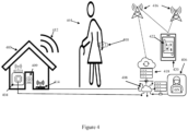
- FIG 4 shows a person 401 wearing an autonomously powered SOS device 400 (which may be in the form of device 100 of Figure 1 , or of device 200 of Figure 2 , or of some other form, and preferably includes all or most of the features and functionality described with reference to Figure 3 ) on a wrist.
- the SOS device 400 includes a transceiver arrangement that within the home 403 may communicate with a central unit or base station 404, for example using a relatively low power channel in an assigned ISM frequency band (such as an 868MHz band).
- an assigned ISM frequency band such as an 868MHz band
- the central unit 404 may store contact details for one or more people/organisations to be contacted in the event of a fall or SOS alert is triggered within the home, the central unit potentially using a cellular, wired telephony, or cabled broadband connection to signal an alert, possibly including a pre-recorded message, in respect of the particular SOS device (which is likely to be associated with a particular individual, so that that person's name or the ID of the SOS device are in effect synonymous), so that someone can be summoned to the premises to render aid/assistance to the person who has fallen or raised the SOS alert. Additionally or alternatively, the central unit 404 may be arranged to co-operate with a dedicated remote monitoring station 406 that potentially serves many SOS devices.
- Such a dedicated remote monitoring station 406 may also provide support for SOS devices that are arranged to report alerts (whether falls or SOS events) while out of range of the central unit 404.
- the SOS device preferably includes at least one RF transmitter configured to operate on a low power wide area cellular (e.g. 3GPP) network such as LTE Cat M and NB IoT, or equivalents, and/or at least one RF transmitter configured to operate on a low power wide area network (LPWAN) that uses unlicensed frequency spectrum - such as Sigfox or LoraWAN.
- a low power wide area cellular e.g. 3GPP
- LTE Cat M and NB IoT LTE Cat M and NB IoT
- LPWAN low power wide area network
- the central unit 404 may also serve as the central unit/controller of a security monitoring system of the kind that, in an armed state, is operable to report security breaches (such as the opening of a door or window, detected by a door/window sensor) to a remote monitoring station 406, typically over a broadband connection to the internet 408, or via a wireless connection 412.
- the security monitoring station 406 may support many such security monitoring installations.
- the same or a different monitoring centre may be used to monitor SOS alerts, fall alerts, etc., from the SOS device 400.
- the security monitoring installation may include not just one or more sensors for detecting the opening of doors or windows, but may also include one or cameras such as video camera 409 which the remote monitoring station 406 may be able to turn on, via the central unit, so that video or still images may be sent to the remote monitoring station for review after an incident alert.
- video camera 409 which the remote monitoring station 406 may be able to turn on, via the central unit, so that video or still images may be sent to the remote monitoring station for review after an incident alert.
- the figure illustrates a security monitoring system for premises, the system being of the kind that, in an armed state, is operable to report security breaches, such as the opening of a door or window, detected by a door/window sensor (such as a magnetic contact sensor), to a remote monitoring station, the system being configured to: receive alert messages from a device at the premises, the device being according to any variant of the first aspect;
- security breaches such as the opening of a door or window, detected by a door/window sensor (such as a magnetic contact sensor), to a remote monitoring station, the system being configured to: receive alert messages from a device at the premises, the device being according to any variant of the first aspect;
- the SOS device 400 may be configured to transmit its reports to the home node or central unit using a short-range communications protocol, such as Bluetooth, Bluetooth Low Energy, or Thread, if available, in preference to using Wi-Fi, through the use of an appropriate internal transmitter (which may be provided in the form of a transceiver).
- a short-range communications protocol such as Bluetooth, Bluetooth Low Energy, or Thread
- the SOS device 100 may be configured to use Wi-Fi, provided that a Wi-Fi network with a known SSID and sufficient signal strength (e.g. better than -67dBm) is available.
- the SOS device 400 may be configured to use a cellular network (e.g.
- the device 400 may have no capability to send or receive Wi-Fi signals, although as previously noted it may be useful to provide the capability to receive Wi-Fi signals and to detect SSIDs (so that the device can use these in determining its location) whether or not there is any capability to transmit Wi-Fi signals.
- embodiments of the SOS device 400 may further default to using a long-range communication protocol such as SigFox (RTM) in the event that the device finds itself out of range of the central unit or home node and also unable to connect to PLMNs (or unable to secure a reliable connection, possibly through being out of range).
- RTM long-range communication protocol
- SigFox supports long range communication (30-50km in rural areas, 3-10km in urban areas), low data rates (12 bytes per message, with a maximum of 140 messages a day per device), and uses a sub-GHz band (868MHz in Europe) and employs BPSK modulation with ultra-narrowband technology.
- End devices equipped with SigFox technology transmit data to SigFox base stations which then forward the data to SigFox servers. This is where the data are processed before the results are sent to the respective end devices for visualisation - in the present case for a user or service provider to determine the location of the SOS device and to receive any report of a fall or SOS event.
- the reports from the SOS device 400 may be directed towards a remote monitoring centre 406 and/or to a networked storage arrangement (e.g. one or more servers in the cloud) 418 which functions as a tracking system backend from where they are optionally pushed to a device, such as a smart phone 420, of a family member of the SOS device wearer.
- a device such as a smart phone 420, of a family member of the SOS device wearer.
- the smart phone 420 or other device has a software application (app) 422 installed for displaying reports received (directly or indirectly) from the SOS device, and optionally for tracking and displaying routes defined by reported locations, although the SOS device may itself track routes and supply these in its reports.
- the SOS device may be configured to report tracked routes only when the tracking device is away from a home location - which may be defined using geofencing, either using local network availability (e.g., particular Wi-Fi SSID availability, if the device has the capability to detect these) or using GNSS signals or some other technique to derive location.
- Location and presence data may also be transmitted from the SOS device to the relative's device 420 directly, e.g. using Bluetooth or Thread or the like, or simply over local Wi-Fi (if the device is Wi-Fi capable), when the two devices are sufficiently close to each other or sufficiently close to the same Wi-Fi network, rather than the reports and data having to traverse the Internet.
- reports may be transmitted to the relative's device 420 using a low power wide area cellular network such as LTE Cat M or NB IoT or the like.
- the SOS device 400 may be configured to exhibit a first behaviour when the determined location is one of one or more first locations and to exhibit a second behaviour when the determined location is a location other than one of the one or more first locations.
- the SOS device 400 may be configured to perform location read attempts, and report on the result of these, less frequently when the device knows that it is at "home" (a first location) than when it is away from "home".
- the first location may be narrowly defined - for example inside the home, so that the garden or grounds of the home constitute location(s) other than one of the one or more first locations, because of the potentially enhanced risk of falls outdoors.
- the designation of a location as a first location will typically be based on the perceived "safety" of the location, that is the level of risk. This may depend not only upon the perceived threat level at the relevant premises, but also on the proximity of possible threat actors and/or the safety provided by the presence of neighbours, law enforcement, security cameras, neighbourhood watch schemes, and the like.
- a convenient way for the device 400 to determine that the location of the device is one of the one or more first locations is to use a detected wireless network identity and a received signal strength corresponding to the detected wireless network identity.
- the device may be configured to recognise particular SSIDs as being associated with the one or more first locations and use signal strength data (e.g., RSSI) to determine whether the device 400 is within the relevant first location or outside it.
- signal strength data e.g., RSSI
- the device may be configured to define a first location as one within which the RSSI for a particular SSID is better than -65dBm or better than -64dBm.
- the device 400 determines that the location of the device is one of the one or more first locations is to do so based on the position of the device with respect to one or more geofences whose parameters are stored in the device.
- the geofences may be established based on data from a satellite navigation (GNSS) function such as GPS embodied in the device 400, and/or using received signal strengths from one or more wireless networks (e.g. one or more Wi-Fi networks, and/or signals from multiple PLMN base stations).
- GNSS satellite navigation
- the device may be configured to use the Skyhook (RTM) positioning service, and optionally the positioning service provided by Qualcomm (RTM) - notably if the device incorporates an LTE modem from Qualcomm - such as the MDM9205.
- RTM Skyhook
- Qualcomm Qualcomm
- the second behaviour includes causing the reader to perform location read attempts, and reporting, more frequently than according to the first behaviour.
- the device 400 may be configured to determine location and perform a read attempt every minute or every few minutes when the device is in one of the one or more first locations, and perhaps to report location as infrequently as once every 10 minutes ( to save battery life) while in the first location but to determine location and perform a read attempt at a frequency of more than once per minute, when the device is in a location other than one of the one or more first locations.
- the frequency of location reporting according to the second behaviour may depend upon the rate of change of location or upon, for example, the number of steps taken since the last location report. In this way, battery life is prolonged while still enabling track to be kept of the location of the wearer.
- the second behaviour includes transmitting a route based on locations determined since the determined location ceased to be one of the one or more first locations.
- the processor of the SOS device is configured to increase a rate at which location read attempts are made in the event that a speed of movement of the device is determined to exceed a first non-zero threshold speed.
- the threshold speed may be based on the average normal walking speed of the device wearer 401 - which may either be determined through measurement using the tracking app 422 on the relative's device 420, if necessary in conjunction with the SOS device 100 (when determining the wearer's average walking speed), or based on standard figures.
- the first non-zero threshold speed may for example be set at between 1.3 and 2.5 metres per second, for example at 2 metres per second.
- Additional non-zero threshold speeds may be set, with a further increase in sampling rate, for use in tracking a wearer in the event of the wearer being transported in a vehicle - for example a second threshold of 14 metres per second (50 KPH), and a third of 28 metres per second (100 KPH), with sampling (and optionally reporting) rates increasing for each higher threshold speed, e.g. to a rate as high as once per second or once every two seconds.
- the device 100 may be configured to power down its RF transceivers 312/314 for extended periods, to reduce power consumption and thereby extend battery life, only powering up an RF transceiver periodically (for example every 10, 15, or 30 minutes) unless a fall is detected or an SOS event is alerted by the activation of the SOS button 110/210.
- the accelerometer 318 and the processor 302 remain powered while the RF transceivers are in their powered down state, the processor also being responsive to operation of the SOS button 110/210.
- the device may be configured to determine (e.g. using GNSS) and report its location to the system back end (e.g.
- the device 100 may be configured periodically to activate a short-range RF transceiver, transmit a message (preferably containing a device identifier, and optionally a message identifier) to the central unit 404, and wait for a reply from the central unit 404.
- the reply from the central unit 404 preferably includes an identifier (possibly a message identifier that was used by the device when making the relevant call, and/or an identifier for the central unit). Communication between the device and the central unit may also be encrypted using encryption keys shared between the two devices.
- the reply from the central unit 404 may also include a request for the device to stay in listening mode (i.e. with the transceiver powered up) until instructed to power down the transceiver (or until the expiry of a predetermined wait time).
- a request for the device to stay in listening mode i.e. with the transceiver powered up
- the central unit 404, and thus the remote monitoring centre 406, are able to communicate with the device periodically (according to the device's scheduled contact events).
- the central unit 404 will not receive the short-range transmission from the device 400, and consequently the device 100 will not receive a reply from the central unit 404. In this way the device will determine (if it is not already aware) that it is no longer "at home".
- the device 400 may use this determination as a trigger to activate the navigation module 328 to determine the device's location. Having determined the device location, the device may report its current location to a remote monitoring entity (e.g. remote monitoring station 406 or carer's device 420, or both), although the device may be configured only to report its location if it is outside a (potentially, user-defined) safe zone.
- a remote monitoring entity e.g. remote monitoring station 406 or carer's device 420, or both
- the processor 302 may take account not just of determined location but also of velocity (which, with GNSS, can be determined based on differences of consecutive carrier phase measurements - TDCP time differenced carrier phase, as well as by using simple differences between two consecutive positions).
- the device may power down the GNSS module between position determination events.
- the frequency with which the device wakes up its RF transceiver to report to the system back end may increase, at least when the device is outside a predetermined safe zone (which may be based simply on distance, but which may take account of the perceived safety/danger of certain locations).
- the frequency of position determination events may increase in the event that the determined velocity of the device exceeds one or more thresholds (e.g. above walking speed, above 30km/h, above 50 km/h, above 100 km/h).
- the device may also be configured to capture an audio sample in the event that one or more of these velocity thresholds is breached, optionally transmitting the audio sample with the next position report to the system back end (or monitoring station) - or optionally only transmitting the audio clip upon receiving a request to transmit it.
- the device 400 may also determine that it is no longer "at home” by using the step counting function. As previously noted, the accelerometer 318 and the processor 302 remain powered even when the RF transceivers are powered down, so that the device is always ready to detect a fall. The device 400 is preferably also arranged to count steps (more generally detect user activity) even when the RF transceivers are powered down. Also, if the device 400 includes a gyroscope 319, signals from the gyroscope 319 may be used possibly in conjunction with signals from the accelerometer 318, to determine whether the device 400 is still "at home".
- devices according to aspects of the invention may be configured to be contactable all the time ("always on" reception), such an approach is likely to be expensive in terms of battery consumption.
- a preferred alternative is to configure the device to shut down its RF transceiver(s) and for the device to initiate contact with the back-end, e.g. periodically, or in an emergency, or internal watch alert.
- the back-end which may be the monitoring station 406 can instruct the device to keep open connection for a desired period, and/or reprogram (reschedule) a next communication window.
- a device whose RF transceivers are only periodically active can still support two-way communication - allowing message transmission to the device, or "pinging" from the back-end to the device (when connected), and not just communications from the device to the back-end.
- the device may be configured only to activate a transmitter (optionally transceiver) that supports communication over a low power wide area cellular network, such as LTE Cat M or NB IoT or the like LTE, when the device determines that it is out of range of the central unit or when it is otherwise aware that it is no longer "at home” (e.g. based on information from the navigation module).
- a transmitter optionally transceiver
- the device may be configured to capture an audio clip in the event that a fall is detected, or an SOS alert is raised.
- the audio clips may be transmitted to the remote monitoring station automatically, but the system may be configured only to transmit the audio clips on request from the remote monitoring station.
- the remote monitoring station can use the audio clip as context for the event report and can instruct the device to send further audio clips if further context is required. That is, when the device reports an event and provides an audio clip, the back end can keep the connection open with the device in order to monitor the situation via audio clips. The back end may also force the device to report its position, for example determined via GNSS, and velocity if appropriate.
- the device is preferably configured to count steps, based on data from the accelerometer 318. Step count can be used as an input to an adaptive control for controlling how frequently to check for the detected position and/or how frequently or when the device should contact the central unit 404 or the system back-end 418 or remote monitoring centre 406.
- the device may be given a step-count threshold to trigger check on position (e.g. step-count since last position check, or step count so far today).
- Devices according to embodiments of the invention may be configured so that when they are out of range of the base station 404 they report position after a certain number of steps, as well as reporting periodically.
- steps taken at home may be counted towards a daily activity target, they may not be counted as relevant to a step count influenced location report.
- steps taken at home may be counted towards a daily activity target, they may not be counted as relevant to a step count influenced location report.
- the device may only report in to the system back end according to its usual schedule, but if the wearer walks more than 450 steps the device may wake and report its position - because perhaps such long excursions may be a source of concern (for example if the wearer is suffering from dementia or is rather frail) - in this way, a carer (and or a monitoring station) may keep track on the wearer who needs such oversight.
- step counting will be performed using data from the accelerometer, but of course other technology of the type used in pedometers (ball and spring, pendulum, etc.) could be used in lieu of or in addition.
- the step counting function will be based on a MEMS sensing arrangement, such as the accelerometer 318.
- a carer's or relative's WTRU device 420 e.g. a smartphone, provided with an app 422 may be used to:
- step count could be shared with the carer's device, but if such a level of detail were considered invasive then relative levels of activity might be shared - perhaps with comparison to recent daily counts or step/activity targets, possibly broken down into parts of the day (e.g. an activity target for the morning, another for the afternoon, etc.), and possibly also considering the length of intervals between periods of activity. So, for example the carer's app may receive a message such as "user's activity has dropped by 25% in the last week compared to the average for the previous month (or longer period)"
- the device may be configured to act as a tag to arm and/or disarm the system, and if the system is linked to electronically controlled locks on access doors, the device may be configured to unlock and/or lock any such locks.
- Such control could be performed using BLE, or the short range communication protocol used for communication with the central unit, or the device may include an NFC antenna and related hardware to transmit instructions, using NFC, to a disarm node of the security monitoring system.
- the device may include a haptic transducer 330 to provide haptic feedback, for example when an SOS call is made, optionally also when a fall is reported, and optionally when a message is received confirming that the SOS call has been received by the remote monitoring centre 406.
- the device is configured to display, on face 104/204 or display 109/209, textual messages to the effect that an SOS call has been made, that the call has been received at the remote monitoring centre, and that help is on its way (as appropriate).
- the device may include a capability to determine the wearer's heart rate (and possibly also to detect arrhythmias and other irregularities). Such devices may be arranged to report average heart rate (and/or high or low values) whenever reporting in to the system back end, and/or they may report current heart rate in the event of reporting a fall or an SOS event. Optionally, the device may raise an alert and report an event to the system back end (without waiting for the next scheduled reporting event) in the event that a high or low heart rate threshold is breached and/or the data form the heart rate monitoring subsystem indicate some kind of cardiac event or emergency.
- the device may additionally or alternatively include a capability to determine the wearer's blood oxygen saturation, and be configured to report average oxygen saturation (and/or high or low values) whenever reporting in to the system back end, and/or they may report current oxygen saturation in the event of reporting a fall or an SOS event.
- the device may raise an alert and report an event to the system back end (without waiting for the next scheduled reporting event) in the event that a low blood oxygen saturation threshold is breached.
- Information from heart rate monitoring and/or oxygen saturation may be used to provide a "worn" signal to indicate whether the device is actually being worn or that it is no longer being worn.
- information from the accelerometer may be used to determine whether the device is being worn or not.
- Devices according to aspects of the invention may be arranged to co-operate with a Wi-Fi sensing arrangement in the home environment. That is, when the device is "at home” rather than away from home, a Wi-Fi sensing arrangement in the home may be arranged to provide information that is complementary to information provide by a device according to an aspect of the invention.
- the fall-detection function of the device may supplement information from a Wi-Fi sensing arrangement.
- Wi-Fi sensing may be able not only to determine the location of someone within the home but also determine whether that person is sitting, standing, or lying down - possibly even being able to detect a fall.
- the home hub or an associated back end or remote monitoring installation may be able to integrate information from such a device with information from Wi-Fi sensing to confirm an initial finding from either data source.
- a device according to aspects of the invention may be configured so that their fall-detection algorithm is set to be more sensitive while the device is "at home” - and in particular when the device is within an area of the home that is subject to Wi-Fi sensing.
- a device may be configured to detect that it is within such an area based on a combination of detected SSID(s) and signal strength(s) (e.g. RSSI).
- Wi-Fi sensing functionality may be built into the home hub or central unit, using Wi-Fi illumination signals from Wi-Fi enabled devices (such as cameras of a security monitoring system, Wi-Fi-enabled doorbell, "smart” sockets and other “smart” devices). Also while at home, if the SOS device is being worn, any falls detected by Wi-Fi sensing can be verified via fall-detection in the device, providing an extra layer of verification to the monitoring station. While away from home, the device's fall-detection algorithm can be set to normal sensitivity to reduce risk of false-positives.
Landscapes
- Health & Medical Sciences (AREA)
- General Physics & Mathematics (AREA)
- Business, Economics & Management (AREA)
- Emergency Management (AREA)
- Physics & Mathematics (AREA)
- General Health & Medical Sciences (AREA)
- Gerontology & Geriatric Medicine (AREA)
- Psychology (AREA)
- Computer Security & Cryptography (AREA)
- Social Psychology (AREA)
- Engineering & Computer Science (AREA)
- Psychiatry (AREA)
- Alarm Systems (AREA)
- Emergency Alarm Devices (AREA)
Priority Applications (2)
| Application Number | Priority Date | Filing Date | Title |
|---|---|---|---|
| EP23383141.1A EP4553802A1 (fr) | 2023-11-07 | 2023-11-07 | Dispositifs de surveillance personnels portables et systèmes associés |
| PCT/EP2024/081437 WO2025099126A2 (fr) | 2023-11-07 | 2024-11-07 | Dispositifs de surveillance personnelle pouvant être portés sur soi et systèmes associés |
Applications Claiming Priority (1)
| Application Number | Priority Date | Filing Date | Title |
|---|---|---|---|
| EP23383141.1A EP4553802A1 (fr) | 2023-11-07 | 2023-11-07 | Dispositifs de surveillance personnels portables et systèmes associés |
Publications (1)
| Publication Number | Publication Date |
|---|---|
| EP4553802A1 true EP4553802A1 (fr) | 2025-05-14 |
Family
ID=88793024
Family Applications (1)
| Application Number | Title | Priority Date | Filing Date |
|---|---|---|---|
| EP23383141.1A Withdrawn EP4553802A1 (fr) | 2023-11-07 | 2023-11-07 | Dispositifs de surveillance personnels portables et systèmes associés |
Country Status (2)
| Country | Link |
|---|---|
| EP (1) | EP4553802A1 (fr) |
| WO (1) | WO2025099126A2 (fr) |
Citations (3)
| Publication number | Priority date | Publication date | Assignee | Title |
|---|---|---|---|---|
| US20130076523A1 (en) * | 2011-09-28 | 2013-03-28 | SilverPlus Inc. | Low power location-tracking device with combined short-range and wide-area wireless and location capabilities |
| US20160379476A1 (en) * | 2013-11-26 | 2016-12-29 | Kytera Technologies Ltd. | Systems and methods for analysis of subject activity |
| CN110719363A (zh) * | 2019-09-20 | 2020-01-21 | 奇酷互联网络科技(深圳)有限公司 | 定位上报方法、装置、智能终端和存储介质 |
Family Cites Families (11)
| Publication number | Priority date | Publication date | Assignee | Title |
|---|---|---|---|---|
| US20120235860A1 (en) * | 2006-04-25 | 2012-09-20 | Ghazarian Ohanes D | Automatic GPS tracking system with passive or active battery circuitry |
| KR101267405B1 (ko) * | 2012-09-25 | 2013-05-30 | 강우석 | 실내 측위를 위한 위치 정보 제공 장치, 방법, 및 기록 매체 |
| CN105101085A (zh) * | 2015-07-23 | 2015-11-25 | 小米科技有限责任公司 | 出行日志的建立方法和装置 |
| US10311706B2 (en) * | 2015-10-06 | 2019-06-04 | Ademco Inc. | System and method for smart intrusion control using wearable BLE devices |
| US10142772B2 (en) * | 2015-12-16 | 2018-11-27 | Qualcomm Incorporated | Systems and methods for emergency data communication |
| US10629048B2 (en) * | 2017-09-29 | 2020-04-21 | Apple Inc. | Detecting falls using a mobile device |
| LU100813B1 (en) * | 2018-06-05 | 2019-12-05 | Essence Smartcare Ltd | Identifying a location of a person |
| WO2020028157A1 (fr) * | 2018-07-30 | 2020-02-06 | Unaliwear, Inc. | Dispositif et système d'assistance |
| US10762769B1 (en) * | 2019-03-28 | 2020-09-01 | Amazon Technologies, Inc. | Sending signals for help during an emergency event |
| US11190924B2 (en) * | 2019-11-05 | 2021-11-30 | In-Tech Enterprise Ltd. | Tracking device for a track and locate system |
| US11854326B2 (en) * | 2021-10-20 | 2023-12-26 | The Adt Security Corporation | Authentication of wearable devices associated with a premises security system |
-
2023
- 2023-11-07 EP EP23383141.1A patent/EP4553802A1/fr not_active Withdrawn
-
2024
- 2024-11-07 WO PCT/EP2024/081437 patent/WO2025099126A2/fr active Pending
Patent Citations (3)
| Publication number | Priority date | Publication date | Assignee | Title |
|---|---|---|---|---|
| US20130076523A1 (en) * | 2011-09-28 | 2013-03-28 | SilverPlus Inc. | Low power location-tracking device with combined short-range and wide-area wireless and location capabilities |
| US20160379476A1 (en) * | 2013-11-26 | 2016-12-29 | Kytera Technologies Ltd. | Systems and methods for analysis of subject activity |
| CN110719363A (zh) * | 2019-09-20 | 2020-01-21 | 奇酷互联网络科技(深圳)有限公司 | 定位上报方法、装置、智能终端和存储介质 |
Also Published As
| Publication number | Publication date |
|---|---|
| WO2025099126A3 (fr) | 2025-06-19 |
| WO2025099126A2 (fr) | 2025-05-15 |
Similar Documents
| Publication | Publication Date | Title |
|---|---|---|
| US12027033B2 (en) | Wearable personal safety devices and methods of operating the same | |
| US7259671B2 (en) | Proximity aware personal alert system | |
| US5797091A (en) | Personal communication system and method of use | |
| EP1891615B1 (fr) | Systeme de surveillance de parametres physiologiques d'un patient, et procede et produit de programme informatique associes | |
| US5629678A (en) | Personal tracking and recovery system | |
| US8116724B2 (en) | System containing location-based personal emergency response device | |
| EP2704119B1 (fr) | Détection de chute | |
| US20150228176A1 (en) | Ecg-enabled personal emergency response systems | |
| WO2009124326A1 (fr) | Système et appareil émetteur-récepteur de radiofréquence | |
| US20220301407A1 (en) | Wireless patient monitoring compliance system | |
| US20040080421A1 (en) | Monitoring and alert system | |
| US20180224517A1 (en) | Tracking system and method | |
| US10643456B2 (en) | Alarm system | |
| CN108028006B (zh) | 基于个人求助按钮的签到服务 | |
| Gjoreski et al. | Using smartwatch as telecare and fall detection device | |
| KR20180028358A (ko) | 단말기 및 그 제어 방법 | |
| JP7355721B2 (ja) | 看視システム、被看視者端末、及び看視方法 | |
| EP4553802A1 (fr) | Dispositifs de surveillance personnels portables et systèmes associés | |
| JP2020113017A (ja) | 通報用移動端末、通報システム及び通報方法 | |
| EP0840265A1 (fr) | Système d'alarme pour détecter l'éloignement entre plusieurs transmetteurs synchrones et un récepteur | |
| EP2070066A2 (fr) | Procede de teleassistance, equipement pour la mise en uvre de ce procede et montre associee a un tel equipement | |
| KR100386702B1 (ko) | 응급환자 감시 시스템 | |
| AU2016100116A4 (en) | Unsupervised Luggage Protection System | |
| KR200295653Y1 (ko) | 사용자의 위치파악이 가능한 무선단말장치 | |
| Pérez-Rubio et al. | Wearable-Based System For The Ubiquitous Tracking Of Vulnerable People In Remote Areas |
Legal Events
| Date | Code | Title | Description |
|---|---|---|---|
| PUAI | Public reference made under article 153(3) epc to a published international application that has entered the european phase |
Free format text: ORIGINAL CODE: 0009012 |
|
| STAA | Information on the status of an ep patent application or granted ep patent |
Free format text: STATUS: THE APPLICATION HAS BEEN PUBLISHED |
|
| AK | Designated contracting states |
Kind code of ref document: A1 Designated state(s): AL AT BE BG CH CY CZ DE DK EE ES FI FR GB GR HR HU IE IS IT LI LT LU LV MC ME MK MT NL NO PL PT RO RS SE SI SK SM TR |
|
| STAA | Information on the status of an ep patent application or granted ep patent |
Free format text: STATUS: THE APPLICATION IS DEEMED TO BE WITHDRAWN |
|
| 18D | Application deemed to be withdrawn |
Effective date: 20251115 |