EP4553874A1 - Schalter mit äquipotentialgeschalteten kontakten und verfahren zum betrieb eines schalters - Google Patents
Schalter mit äquipotentialgeschalteten kontakten und verfahren zum betrieb eines schalters Download PDFInfo
- Publication number
- EP4553874A1 EP4553874A1 EP23383153.6A EP23383153A EP4553874A1 EP 4553874 A1 EP4553874 A1 EP 4553874A1 EP 23383153 A EP23383153 A EP 23383153A EP 4553874 A1 EP4553874 A1 EP 4553874A1
- Authority
- EP
- European Patent Office
- Prior art keywords
- switch
- contact
- fixed
- fixed contact
- movable contact
- Prior art date
- Legal status (The legal status is an assumption and is not a legal conclusion. Google has not performed a legal analysis and makes no representation as to the accuracy of the status listed.)
- Pending
Links
Images



Classifications
-
- H—ELECTRICITY
- H01—ELECTRIC ELEMENTS
- H01H—ELECTRIC SWITCHES; RELAYS; SELECTORS; EMERGENCY PROTECTIVE DEVICES
- H01H3/00—Mechanisms for operating contacts
- H01H3/001—Means for preventing or breaking contact-welding
-
- H—ELECTRICITY
- H01—ELECTRIC ELEMENTS
- H01H—ELECTRIC SWITCHES; RELAYS; SELECTORS; EMERGENCY PROTECTIVE DEVICES
- H01H1/00—Contacts
- H01H1/12—Contacts characterised by the manner in which co-operating contacts engage
- H01H1/14—Contacts characterised by the manner in which co-operating contacts engage by abutting
- H01H1/20—Bridging contacts
-
- H—ELECTRICITY
- H01—ELECTRIC ELEMENTS
- H01H—ELECTRIC SWITCHES; RELAYS; SELECTORS; EMERGENCY PROTECTIVE DEVICES
- H01H1/00—Contacts
- H01H1/12—Contacts characterised by the manner in which co-operating contacts engage
- H01H1/36—Contacts characterised by the manner in which co-operating contacts engage by sliding
- H01H1/42—Knife-and-clip contacts
-
- H—ELECTRICITY
- H01—ELECTRIC ELEMENTS
- H01H—ELECTRIC SWITCHES; RELAYS; SELECTORS; EMERGENCY PROTECTIVE DEVICES
- H01H1/00—Contacts
- H01H1/58—Electric connections to or between contacts; Terminals
- H01H1/5822—Flexible connections between movable contact and terminal
-
- H—ELECTRICITY
- H01—ELECTRIC ELEMENTS
- H01H—ELECTRIC SWITCHES; RELAYS; SELECTORS; EMERGENCY PROTECTIVE DEVICES
- H01H9/00—Details of switching devices, not covered by groups H01H1/00 - H01H7/00
- H01H9/30—Means for extinguishing or preventing arc between current-carrying parts
- H01H9/34—Stationary parts for restricting or subdividing the arc, e.g. barrier plate
- H01H9/36—Metal parts
-
- H—ELECTRICITY
- H01—ELECTRIC ELEMENTS
- H01H—ELECTRIC SWITCHES; RELAYS; SELECTORS; EMERGENCY PROTECTIVE DEVICES
- H01H1/00—Contacts
- H01H1/50—Means for increasing contact pressure, preventing vibration of contacts, holding contacts together after engagement, or biasing contacts to the open position
-
- H—ELECTRICITY
- H01—ELECTRIC ELEMENTS
- H01H—ELECTRIC SWITCHES; RELAYS; SELECTORS; EMERGENCY PROTECTIVE DEVICES
- H01H9/00—Details of switching devices, not covered by groups H01H1/00 - H01H7/00
- H01H9/30—Means for extinguishing or preventing arc between current-carrying parts
- H01H9/34—Stationary parts for restricting or subdividing the arc, e.g. barrier plate
- H01H9/36—Metal parts
- H01H2009/365—Metal parts using U-shaped plates
Definitions
- the present invention relates in general to electric power switches, especially adapted to withstand short-circuit currents.
- An object of the invention is the provision of a switch capable of withstanding short-circuit currents, without being destroyed or deteriorated by the passage of such high currents.
- an object of the invention is to provide a switch of the above-mentioned type, which can be manufactured with reduced material and reduced cost, and which can be easily retrofitted into existing switch designs.
- the invention also refers to a method for operating a switch of the above-described type, for switching On and Off an electric current.
- the admissible short-time withstand current characterizes the ability of an equipment to withstand short-circuit currents, typically very high, for a duration enough to eliminate them by means of circuit breakers or protection devices located downstream of that equipment.
- Short-circuit currents produce 2 types of phenomena in a switch:
- the "admissible short-time withstand current” is defined in several standards, including IEC 60947-2, which gives it the symbol (Icw).
- the associated test makes it possible to test the behavior of a disconnector under both the electrodynamic aspect, when a short-circuit occurs, and under the thermal aspect, by maintaining the current for a given time (normally 0.5 s, 1 s or 3 s).
- the maximum peak current is defined by the standard as a function of the effective current; knowledge of the latter is sufficient to define the (Icw).
- This separation of contacts causes the loss of equipotentiality at the junction of the fixed contact with the moving contact.
- This loss of equipotentiality of the junction causes the potential difference Va-Vb between the junction zone of the fixed contact and the junction zone of the mobile contact to reach a value equal to the maximum voltage of the circuit (380 Vac, 400 Vac) which causes an electric arc whose intensity is the value of (Icw) at that moment, the energy released causes a fire or explosion of the circuit disconnector causing serious damage to installations and even to people.
- FIG 1A shows a conventional switch (1) formed by two fixed contacts (3a,3b) and a movable contact (4) formed by two blades (4a,4b) which in the closed position of the switch are overlapped and in contact with the two fixed contacts (3a,3b).
- the switch (1) incorporates two pressure springs (2, 2') which exerts forces (Fp) pressing the two blades (4a,4b) towards the fixed contacts (3a,3b).
- Fp forces
- the voltage (Va - Vb) shown in Figure 2A would generate electric arcs as shown in Figures 1B & 2C , that in turn might produce welding spots (5a,5b) between blades (4a,4b) and fixed contact (3a) as shown in Figure 2B .
- the invention is defined in the attached independent claims, and satisfactorily solves the above-described drawbacks of the prior art, by the provision of a switch capable of withstanding short-circuit currents maintaining its integrity, that is, without being damaged or destroyed, at least, during enough time to allow other protection devices connected downstream, to open the circuit and interrupt the short-circuit current.
- a first aspect of the invention refers to a switch comprising: at least one fixed contact and at least one movable contact, wherein the movable contact is displaceable between a closed position of the switch in which the fixed and the movable contacts are electrically connected so that a current can circulate through the fixed and movable contacts, and an open position of the switch in which the fixed and movable contacts are spaced apart from each other, so that current circulation through the fixed and movable contacts is impeded.
- the switch further comprising at least one equipotential connecting member electrically connecting the fixed contact and the movable contact in the closed position of the switch. Additionally, a part of the equipotential connecting member is configured to press against the fixed contact and/or the movable contact in the closed position of the switch.
- the equipotential connecting member is configured and arranged in the switch, to assure that the fixed and the movable contacts remain connected in the closed position of the switch, even when the fixed and the movable contacts are separated as consequence of repulsion forces caused by a short-circuit current flowing through the switch, so that the fixed and the movable contacts remain at the same electric potential during the short-circuit event, hence preventing the formation of an electric arc between the two contacts.
- the equipotential connecting member is configured to maintain the fixed and the movable contacts pressed together in the closed position of the switch, in a way in which it assured that the fixed and the movable contacts remain at the same electric potential, even if they are separated due to repulsion forces caused by a short-circuit current.
- the equipotential connecting member is configured as a clamp or clip that embraces the fixed contact or the movable contact or both in the closed position of the switch, in particular the equipotential connecting member embraces the fixed and/or the movable contacts at the parts of the contacts which are overlapped and in contact in the closed position. In this position, a part of the equipotential connecting member, is placed above the fixed contact or the movable contact or both, so that, when the fixed and movable contacts are separated due to a short-circuit current, they would remain connected by the equipotential connecting member, thereby assuring that both contacts are at the same potential.
- the present invention is focused on improving the limits of (Icw) by overcoming the severe electrodynamic effects of high short-circuit currents, eliminating the effects of contact repulsion forces at the initial instant of a short-circuit.
- the equipotential connecting member is arranged and configured such that in the open position of the switch, it is disconnected from the fixed contact or from the movable contact or from both.
- the fixed contact and the movable contact are overlapped and in contact at a contacting surface, and the part of the equipotential connecting member which presses against the fixed contact and/or the movable contact, press in a direction towards that contacting surface.
- the part of the equipotential connecting member which presses against the fixed contact and/or the movable contact is embodied as a flexible metal plate configured to exert pressure on the fixed contact and/or the movable contact in the closed position of the switch due to its flexible characteristic.
- the equipotential connecting member is configured to have a part of the equipotential connecting member permanently attached to the fixed contact, and the part of the same which is configured as a flexible metal plate, overlaps the movable contact and press the movable contact towards the fixed contact in the closed position of the switch to assure that the fixed and movable contacts remain connected.
- the fixed contacts are substantially flat and elongated bodies, each one formed by a rigid metallic piece.
- the switch comprises a first fixed contact and a second fixed contact spaced apart from each other, and the movable contact in the closed position of the switch, is placed in the space in between the first and second fixed contacts and it is electrically connected to the two fixed contacts.
- the movable contact is composed by two blades embodied as generally flat and elongated bodies, each one formed by a rigid metallic piece, wherein the blades are separated and parallel to each other.
- the switch comprises first and second equipotential connecting members, respectively connecting the movable contact with the first and second fixed contacts in the closed position of the switch.
- the first and second fixed contacts are aligned in a first direction
- the movable contact is linearly displaceable in a second direction orthogonal to first direction
- the multipole switch includes a carrier made of an electrically insulating material, and all the movable contacts of the switch are mounted in the carrier so that all the movable contacts move simultaneously between open and closed positions of the multipole switch.
- Another aspect of the invention refers to a method for operating a switch for switching On and Off an electric current.
- the method comprises the step of maintaining a fixed contact and a movable contact of the switch at the same electric potential in a closed position of the switch, when the fixed and movable contacts are electrically connected, while a short-circuit current circulates through the switch.
- the switch is the switch of any of the previously described embodiments.
- the fixed contact and the movable contact of the switch are maintained at the same electric potential in a closed position of the switch, by clamping and pressing together the fixed and movable contacts by means of an equipotential connecting member made of a flexible metallic plate.
- the equipotential connecting member embrace and press together the fixed and the movable contact, at the parts of these contacts that are overlapped and in contact. In this way, if the fixed and movable contact are separated apart as consequence of the circulation of short-circuit current through them, the equipotential connecting member remains connected to the fixed and movable contacts thereby assuring that both contacts are at the same potential.
- the switch of the invention is adapted to operate as a circuit disconnector, which advantageously can be used as head circuit disconnector installed at the head of an electrical circuit, for example an electric distribution board, so that its capacity to withstand a high short-circuit currents without being destroyed, provides enough time for other protection devices connected downstream to react to the short-circuit disconnecting its corresponding part of the installation.
- a circuit disconnector which advantageously can be used as head circuit disconnector installed at the head of an electrical circuit, for example an electric distribution board, so that its capacity to withstand a high short-circuit currents without being destroyed, provides enough time for other protection devices connected downstream to react to the short-circuit disconnecting its corresponding part of the installation.
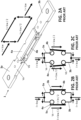
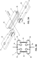
- FIGS 3A, 3B , 4A and 4B show a preferred embodiment of a switch (1) according to the invention, which conventionally comprises first and second fixed contacts (3a,3b) formed by generally flat and elongated bodies, each one formed by a rigid metallic piece, and which are aligned in a first direction (X).
- first and second fixed contacts (3a,3b) formed by generally flat and elongated bodies, each one formed by a rigid metallic piece, and which are aligned in a first direction (X).
- the switch (1) also includes a movable contact (4) composed by two blades (4a,4b) also embodied as generally flat and elongated bodies, each one formed by a rigid metallic piece.
- the blades (4a,4b) are separated and parallel to each other.
- the movable contact (4) moves in a direction (Y) substantially orthogonal to the direction (X) while transiting between the open position of the switch (1) ( Figure 3A ) and the closed position of the switch ( Figure 4A ) .
- the separation distance between the blades (4a,4b) generally matches the thickness of the fixed contacts (3a,3b), so in the closed position of the switch ( Figure 4A ), the two blades are overlapped and in contact with the fixed contacts, one blade (4b) in contact with the lower side of the fixed contacts, and the other blade (4a) in contact with the upper side of the fixed contacts.
- the movable contact (4) in the closed position of the switch is placed in the space in between the first and second fixed contacts (3a,3b), thus, the movable contact (4) is coaligned with the fixed contacts (3a,3b).
- the above-described switch (1) incorporates two equipotential connecting members, namely a first equipotential connecting member (6a) electrically connecting in the closed position of the switch (1), the first fixed contact (3a) with the two blades (4a,4b) at one end of the blades, and a second equipotential connecting member (6b) electrically connecting the second fixed contact (3b) with the two blades (4a,4b) at the other end of the blades, as shown in Figures 3A & 4A .
- a first equipotential connecting member (6a) electrically connecting in the closed position of the switch (1)
- a second equipotential connecting member (6b) electrically connecting the second fixed contact (3b) with the two blades (4a,4b) at the other end of the blades
- the two equipotential connecting members (6a,6b) are configured to maintain the fixed and the movable contacts pressed together in the closed position of the switch, in a way in that it is assured that the fixed and the movable contacts remain at the same electric potential, even if they are separated due to repulsion forces caused by a short-circuit current.
- the voltages: (Va) at the first fixed contact (3a), (Vb) at the upper blade (4a) and the voltage (Vc) at the first equipotential connecting member are the same.
- two equipotential connecting members (6a,6b) are configured to maintain the fixed and the movable contacts pressed together, not to serve as pressing members as the pressing members (2, 2') of Figure 1A , but to assure the electrical connection between fixed and movable contacts while the movable contacts levitate from the fixed contacts.
- each of the equipotential connecting member (6a,6b) is attached permanently to a fixed contact (3a, 3b) and it is configured to make contact with the blades (4a, 4b) in the closed position of the switch.
- a part of each equipotential connecting member (6a,6b) is a flexible metal plate, which overlaps one of the blades (4a,4b) and press that blade against a fixed contact in the closed position of the switch.
- the equipotential connecting members (6a,6b) are attached to the blades (4a, 4b), and are pressed against the fixed contacts (3a,3b) in the closed position of the switch (1).
- Each equipotential connecting member (6a,6b) is embodied as a metallic plate conformed as a clamp, which embraces the fixed and the movable contacts at the overlapped parts of the fixed and movable contacts, in the closed position of the switch.
- the equipotential connecting member (6a,6b) press the blades and fixed contact together in the closed position of the switch.
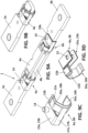
- Each equipotential connecting member (6a,6b) has a central part (8) having a U-shaped configuration in a cross-sectional view, and first and second tabs (9, ⁇ 9') protruding in opposite directions from the central part (8).
- the central part (8) is configured and dimensioned so that a fixed contact (3a,3b) can be tightly received inside, so that each member (6a,6b) is attached to an edge of a fixed contact (3a,3b) by means of the respective central part (8), as better shown in Figure 6B .
- the central part (8) has wings (8a,8b) conformed to have anchors (10) which engage with the respective fixed contact (3a,3b).
- Each tab (9,9') has a first section which is coplanar with the central part (8), and a second section which is folded with respect to the first section.
- a second section of each tab (9,9') is an inclined with respect to a plane defined by a blade (4a,4b), and these inclined parts (11,11') are flexible parts which are flexed due to its contact with the blades (4a,4b) in the closed position of the switch, as shown for instance in Figure 6D .
- the inclined parts (11,11') diverge with respect to the central part (8). In this way, the inclined parts (11,11') are pressed against a blade (4a,4b) of the movable contact, and exert pressure on the blades due to its flexible characteristic.
- each member (6a,6b) are pressed against the blades (4a,4b) in a direction (indicated by arrows in Figure 6D ) towards a contacting surface at which the fixed contact and the blades (4a, 4b) are overlapped and in contact. Additionally, inclined parts (11,11') extend above the blades (4a, 4b).
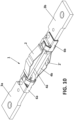
- FIGS 7A to 7C show an alternative configuration of the equipotential connecting members (6a,6b), which have the same parts as the members described above in relation to Figure 6A , that is, they also have a central part (8) with wings (8a, 8b) both provided with anchors (10), and first and second tabs (9,9') protruding in opposite directions from the central part (8).
- the first and second tabs (9,9') are configured as a L-shaped flexible parts (11,11'), which are flexed by its contact with the flanges (4a, 4b) so that these parts (11, 11') are pressed against the fixed contacts, and are placed above the flanges (4a, 4b) in the closed position of the switch (1).
- the two arms of the L-shaped parts are arranged to form an angle within the range 85° to 90°.
- the equipotential connecting members (6a,6b) are formed as double-wall bodies, that is, each member has a first wall and a second wall with a similar configuration than the first wall, and overlapped and in contact with the first wall. That configuration of the equipotential connecting members (6a,6b), is a reinforced version of the same, capable of withstanding higher repulsion forces.
- each equipotential connecting member (6a,6b) has a first U-shaped wall (12a) and a second U-shaped wall (12b) overlapped and in contact with the first U-shaped wall (12a). These two walls (12a, 12b) have overlapping passing-through bores (13), for their attachment to a fixed contact (3a, 3b) by means of a rivet (14).
- each of the equipotential connecting member (6a,6b) has an attaching part (15a, 15b) and a clamping part (16a, 16b) both joined by a central part (17a, 17b).
- the attaching part (15a, 15b) is U-shaped and it is adapted to be attached permanently to a fixed contact (3a, 3b) for example by means of a perforations (13) and a rivets (14).
- the clamping part (16a, 16b) has two tabs protruding in opposite directions from the central part (17a, 17b), wherein each tab has a folding line (18a,18b) which forms two inclined sections.
- each of the equipotential connecting member (6a,6b) is also formed as double-wall bodies having a first wall (12a) and a second wall (12b), wherein the second wall (12b) replicates the shape of the first wall (12a), and it is overlapped and in contact with the first wall (12a).
- the equipotential connecting members (6a,6b) can be easily installed during the manufacturing process of a switch without the need of modifying an existing design of the switch components, that is, the invention can be easily retrofitted into existing assembly manufacturing process of a switch of the above-described type.
- the switch (1) of the invention in addition to the equipotential connecting members (6a,6b), can be provided with conventional press members (2,2') in the form of a leaf spring.
- a multipole switch can be formed by arranging several switches (1) parallel to each other, and having all the movable contacts (4) mounted on a common carrier (not shown) to move simultaneously.
- the method of the invention is illustrated in any of the previously described embodiments of the invention, wherein the method involves maintaining a fixed contact and a movable contact of the switch at the same electric potential in a closed position of the switch, by clamping and pressing together the fixed and movable contacts by means of an equipotential connecting member made of a flexible metallic plate.
Landscapes
- Physics & Mathematics (AREA)
- Electromagnetism (AREA)
- Contacts (AREA)
Priority Applications (3)
| Application Number | Priority Date | Filing Date | Title |
|---|---|---|---|
| EP23383153.6A EP4553874A1 (de) | 2023-11-10 | 2023-11-10 | Schalter mit äquipotentialgeschalteten kontakten und verfahren zum betrieb eines schalters |
| US18/938,964 US20250157748A1 (en) | 2023-11-10 | 2024-11-06 | Switch incorporating equipotentially connected contacts and method for operating a switch |
| CN202411574563.1A CN119993761A (zh) | 2023-11-10 | 2024-11-06 | 开关、多极开关以及操作开关以将电流接通和切断的方法 |
Applications Claiming Priority (1)
| Application Number | Priority Date | Filing Date | Title |
|---|---|---|---|
| EP23383153.6A EP4553874A1 (de) | 2023-11-10 | 2023-11-10 | Schalter mit äquipotentialgeschalteten kontakten und verfahren zum betrieb eines schalters |
Publications (1)
| Publication Number | Publication Date |
|---|---|
| EP4553874A1 true EP4553874A1 (de) | 2025-05-14 |
Family
ID=88833715
Family Applications (1)
| Application Number | Title | Priority Date | Filing Date |
|---|---|---|---|
| EP23383153.6A Pending EP4553874A1 (de) | 2023-11-10 | 2023-11-10 | Schalter mit äquipotentialgeschalteten kontakten und verfahren zum betrieb eines schalters |
Country Status (3)
| Country | Link |
|---|---|
| US (1) | US20250157748A1 (de) |
| EP (1) | EP4553874A1 (de) |
| CN (1) | CN119993761A (de) |
Citations (4)
| Publication number | Priority date | Publication date | Assignee | Title |
|---|---|---|---|---|
| DE839671C (de) * | 1948-10-02 | 1952-05-23 | Siemens Ag | Gegenkontakt fuer messerartige Kontakte |
| EP1914769A2 (de) * | 2006-10-17 | 2008-04-23 | LS Industrial Systems Co., Ltd | Verbindungsleiter und Fingermodul eines Luftleistungsschalters |
| DE202008018351U1 (de) * | 2008-02-20 | 2013-03-12 | Phoenix Contact Gmbh & Co. Kg | Elektrisches Einstellmodul |
| US20140353136A1 (en) | 2011-11-18 | 2014-12-04 | Schaltbau Gmbh | High-current switch |
-
2023
- 2023-11-10 EP EP23383153.6A patent/EP4553874A1/de active Pending
-
2024
- 2024-11-06 CN CN202411574563.1A patent/CN119993761A/zh active Pending
- 2024-11-06 US US18/938,964 patent/US20250157748A1/en active Pending
Patent Citations (4)
| Publication number | Priority date | Publication date | Assignee | Title |
|---|---|---|---|---|
| DE839671C (de) * | 1948-10-02 | 1952-05-23 | Siemens Ag | Gegenkontakt fuer messerartige Kontakte |
| EP1914769A2 (de) * | 2006-10-17 | 2008-04-23 | LS Industrial Systems Co., Ltd | Verbindungsleiter und Fingermodul eines Luftleistungsschalters |
| DE202008018351U1 (de) * | 2008-02-20 | 2013-03-12 | Phoenix Contact Gmbh & Co. Kg | Elektrisches Einstellmodul |
| US20140353136A1 (en) | 2011-11-18 | 2014-12-04 | Schaltbau Gmbh | High-current switch |
Also Published As
| Publication number | Publication date |
|---|---|
| CN119993761A (zh) | 2025-05-13 |
| US20250157748A1 (en) | 2025-05-15 |
Similar Documents
| Publication | Publication Date | Title |
|---|---|---|
| CN114270467A (zh) | 一种断路器 | |
| US9281138B2 (en) | Parallel type transfer switch contacts assemblies | |
| EP4141903B1 (de) | Relais | |
| JPS58103719A (ja) | 接触器 | |
| EP2561535B1 (de) | Stromschalter | |
| CN112219254B (zh) | 用于对电流路径进行直流电流中断的分离设备以及保护开关 | |
| KR20130004884A (ko) | 전기 고전압 온로드 단로기 및 이를 개방하는 방법 | |
| WO2001086675A2 (en) | Flexible shunt for electric power switch | |
| EP2442339A1 (de) | Kontaktanordnung für Vakuumunterbrecher | |
| US20250157748A1 (en) | Switch incorporating equipotentially connected contacts and method for operating a switch | |
| KR100311344B1 (ko) | 전기회로브레이커 | |
| US20170271112A1 (en) | Slot Motor Configuration for High Amperage Multi-Finger Circuit Breaker | |
| US4379956A (en) | Break-jaw construction for a disconnecting switch structure | |
| EP4348690B1 (de) | Schaltvorrichtung und verfahren zum betreiben einer schaltvorrichtung | |
| CN215911378U (zh) | 断路器 | |
| US6414256B1 (en) | Current limiting circuit breaker | |
| EP3981019B1 (de) | Elektrisches kontaktsystem für eine schaltvorrichtung | |
| EP1218899B1 (de) | Elektrischer pol für einen niederspannungsschutzschalter | |
| KR100883872B1 (ko) | 가스 절연 개폐장치용 단로기 | |
| US5072082A (en) | Electromagnetically locked contact blade | |
| KR20170054237A (ko) | 전기 접촉 스위치 및 전기 접촉기 | |
| CN217690986U (zh) | 一种直流继电器的抗黏连结构 | |
| US20240312734A1 (en) | Switch disconnector with an arc extinguishing shield plate | |
| US11817283B2 (en) | Electrical switching system | |
| US20140301004A1 (en) | Low-, medium-, or high-voltage switchgear |
Legal Events
| Date | Code | Title | Description |
|---|---|---|---|
| PUAI | Public reference made under article 153(3) epc to a published international application that has entered the european phase |
Free format text: ORIGINAL CODE: 0009012 |
|
| STAA | Information on the status of an ep patent application or granted ep patent |
Free format text: STATUS: THE APPLICATION HAS BEEN PUBLISHED |
|
| AK | Designated contracting states |
Kind code of ref document: A1 Designated state(s): AL AT BE BG CH CY CZ DE DK EE ES FI FR GB GR HR HU IE IS IT LI LT LU LV MC ME MK MT NL NO PL PT RO RS SE SI SK SM TR |
|
| STAA | Information on the status of an ep patent application or granted ep patent |
Free format text: STATUS: REQUEST FOR EXAMINATION WAS MADE |
|
| 17P | Request for examination filed |
Effective date: 20251113 |