EP4553882A1 - Dispositif de commutation pour un système de barre omnibus - Google Patents
Dispositif de commutation pour un système de barre omnibus Download PDFInfo
- Publication number
- EP4553882A1 EP4553882A1 EP23209559.6A EP23209559A EP4553882A1 EP 4553882 A1 EP4553882 A1 EP 4553882A1 EP 23209559 A EP23209559 A EP 23209559A EP 4553882 A1 EP4553882 A1 EP 4553882A1
- Authority
- EP
- European Patent Office
- Prior art keywords
- switching device
- fuse
- housing part
- intermediate part
- locking
- Prior art date
- Legal status (The legal status is an assumption and is not a legal conclusion. Google has not performed a legal analysis and makes no representation as to the accuracy of the status listed.)
- Withdrawn
Links
Images


Classifications
-
- H—ELECTRICITY
- H01—ELECTRIC ELEMENTS
- H01H—ELECTRIC SWITCHES; RELAYS; SELECTORS; EMERGENCY PROTECTIVE DEVICES
- H01H9/00—Details of switching devices, not covered by groups H01H1/00 - H01H7/00
- H01H9/10—Adaptation for built-in fuses
-
- H—ELECTRICITY
- H01—ELECTRIC ELEMENTS
- H01H—ELECTRIC SWITCHES; RELAYS; SELECTORS; EMERGENCY PROTECTIVE DEVICES
- H01H85/00—Protective devices in which the current flows through a part of fusible material and this current is interrupted by displacement of the fusible material when this current becomes excessive
- H01H85/54—Protective devices wherein the fuse is carried, held, or retained by an intermediate or auxiliary part removable from the base, or used as sectionalisers
-
- H—ELECTRICITY
- H01—ELECTRIC ELEMENTS
- H01H—ELECTRIC SWITCHES; RELAYS; SELECTORS; EMERGENCY PROTECTIVE DEVICES
- H01H9/00—Details of switching devices, not covered by groups H01H1/00 - H01H7/00
- H01H9/10—Adaptation for built-in fuses
- H01H9/104—Adaptation for built-in fuses with interlocking mechanism between switch and fuse
Definitions
- the invention provides a switching device, in particular for a busbar system, preferably a power busbar system with a plurality of power busbars arranged in parallel.
- the switching device is configured to receive fuses in fuse holders and may in particular be a switch disconnector with fuses.
- Busbar systems provide a simple and easy way to power a large number of switching devices, and to monitor them easily. There is a desire to be able to mount as many switching devices as possible on a particular busbar system. Often, the busbar systems are provided inside a switching cabinet where in particular space in the width direction, i.e., from left to right for a person standing in front of the switching cabinet, is at a premium.
- Safety regulations typically require certain distances between power-carrying parts of the switching devices, minimum creepage distances, minimum clearance distances and the like.
- One of these regulations is, for example, the US-American standard UL 98 for enclosed and dead-front switches.
- a switching device in particular for a busbar system, comprising:
- the switching device may specifically be a switch disconnector with fuses.
- the switching device may be provided with fuse holders configured to receive any know fuse, for example fuses such as D0, D01, D02, 10x38, class CC fuses, 14x51, 22x58, 10x85, J30, J60, and/or the like.
- fuses such as D0, D01, D02, 10x38, class CC fuses, 14x51, 22x58, 10x85, J30, J60, and/or the like.
- fuses that are essentially or exactly rotationally symmetrical with regard to their longitudinal extent are easily compatible.
- the clearance distances may be 25,4 mm (1 inch) or larger, and the creepage distances may be 50.8 mm (2 inch) or larger.
- the switching device may fulfill all requirements of the UL 98 standard for safety-enclosed and dead-front switches
- the intermediate part preferably comprises, or is made completely from, an insulating plastic material, preferably a heat-conducting plastic material such with thermal conductivity of 1W/(m*K) (Watt per meter-kelvin) or higher.
- a heat-conducting plastic material such with thermal conductivity of 1W/(m*K) (Watt per meter-kelvin) or higher.
- other parts of the housing, or the entire housing may also comprise, or consist of, a heat-conducting plastic material, in particular with thermal conductivity of 1W/(m*K) (Watt per meter-kelvin) or higher.
- the intermediate part may be assembled from several parts, but preferably is integrally formed, i.e., is formed as a single piece (e.g. by injection molding), and is then inserted into the upper housing part or the lower housing part for the substance-to-substance bonding.
- the substance-to-substance bond has the advantage that it completely and lastingly closes gaps where the bond is made, thus closing clearance distances that would otherwise have existed or could have formed with time because of, for example, warping of the housing or the like.
- direct distances between power-carrying structures can be closed, and much longer creepage distances and clearance distances realized even in the cramped space of a housing with little width.
- the substance-to-substance bond can be realized, for example, by a kind of welding such as ultrasound plastic welding, for example using a sonotrode or hot plate welding.
- plastic laser welding may be used; to this end, some parts of the housing and/or the intermediate part may be provided as transparent so that the welding laser may pass them through to reach the opaque parts to be welded.
- Other variants include, for example, gluing.
- the intermediate part comprises wall portions extending substantially perpendicularly to the longitudinal extent, wherein between every two adjacent fuse-receiving spaces at least one wall portion is arranged.
- the wall portions (which are insulating as well) in particular serve to increase clearance distances and creepage distances so that the width of the switching device can be strongly decreased with respect to similar switching devices of the prior art.
- the fuse-receiving spaces are each bounded, along the longitudinal direction, by a front wall portion and a rear wall portion of the intermediate part.
- the fuse-receiving spaces are each bounded, along the longitudinal direction, by a front wall portion and a rear wall portion of the intermediate part.
- the respective front wall portion or rear wall portion can also, as will be described in the following, provide additional functions, such as guidance features for the fuse holders and the like.
- the fuse holders at least partially have a cylindrical shape, to which inner contours of a corresponding front wall portion and/or rear wall portion are at least partially adapted in shape. This reduces space requirements in the longitudinal direction. Cylindrical contours of the fuse-receiving spaces may be provided by the intermediate part, the upper housing part, and/or the lower housing part, preferably by all of them together.
- the front wall portions and/or the rear wall portions are provided with a ribbed structure on their respective outer side with respect to the fuse-receiving space to which they belong.
- These ribbed structures i.e. structures that each comprise two or more ribs, significantly increase creepage distances along surfaces.
- Each ribbed structure can, for example, comprise between three and ten ribs, wherein the numbers of ribs may be different for front wall portions than for rear wall portions.
- the ribs of the front wall portions point towards the corresponding rear wall portion of the next fuse-receiving space, and/or the ribs of the rear wall portions protrude (or: point, or: stretch) towards the corresponding front wall portions of the preceding front wall portion.
- the ribs themselves may extend in a direction perpendicular to the longitudinal direction, in particular along the width direction. Between the ribs of the front wall portions and the ribs of the corresponding following rear wall portion, an empty space may be provided for increasing clearance distances.
- At least one, or each, rear wall portion is connected to its corresponding front wall portion of an adjacent fuse-receiving space in a volume between said rear wall portion and said front wall portion via a substantially strip-shaped plate portion of the intermediate part, the plate portion extending substantially perpendicularly to said rear wall portion and said front wall portion.
- the strip-shaped plate portion may stand perpendicularly on the width direction and in parallel to the longitudinal direction. Regarding the width direction, the strip-shaped plate portion may be arranged substantially in the middle of the intermediate part.
- the strip-shaped plate portion is, preferably, integrally formed with the wall portions, in particular with the front wall portion and the rear wall portions it connects.
- each rear wall portion and each front wall portion connected by a strip-shaped plate portion comprises one ribbed structure at each of the two sides (in width direction) of the strip-shaped plate portion.
- At least one rear wall portion and at least one front wall portion are, on their respective ends extending towards the top side of the housing, connected to one another via a top-side ribbed structure of the intermediate part.
- Each top-side ribbed structure comprises ribs protruding towards the top side of the housing, for example between three and ten ribs, preferably four, five, or six ribs.
- the top-side ribbed structures increase creepage distances between insides of different fuse-receiving spaces.
- top-side ribbed structured is formed integrally with the front wall portion and/or the rear wall portion which it connects, and further preferably also with other (most preferably all) portions of the intermediate part.
- an inner wall of each fuse-receiving space comprises at least one guiding contour for guiding the fuse holders within the respective fuse-receiving space.
- said inner wall is also formed as a part of the intermediate part and may be part of a front wall portion and/or a rear wall portion of the fuse-receiving space.
- the upper housing part, the lower housing part and/or (preferably) the intermediate part are made from a material, in particular a plastic material, having a thermal conductivity of 1 W/(K*m) (Watt per kelvin-meter) or more.
- the respective part has an improved contribution to the heat management of the switching device, which in turn contributes to being able to provide the switching device with especially small dimensions.
- each fuse-receiving space comprises, along an axial direction of the fuse-receiving space, a base contact terminal, a base contact spring plunger, and a base contact spring element associated with one another and with the corresponding fuse-receiving space.
- Each base contact terminal is configured to contact a first terminal of a fuse when the fuse is inserted into the respective fuse-receiving space.
- the associated base contact spring element is configured to exert a force onto the base contact spring plunger towards the base contact terminal.
- the base contact spring plunger is configured to be driven by said force to press against the first terminal of the fuse when the fuse is inserted into the respective fuse-receiving space. In this way, it is ensured that the fuse is always firmly contacted electrically as well as firmly held in the axial direction. At the same time, this is realized in a space-conserving manner.
- the intermediate part comprises, for each base contact spring plunger, a spring plunger guiding portion, which is configured to guide the base contact spring plunger in its movement along or against the force of the base contact spring element.
- spring plunger guiding portion is formed integrally with other portions of the intermediate part, most preferably integrally with the front wall portion and the rear wall portion of its corresponding fuse-receiving space.
- the switching device comprises a shift linkage movable along the longitudinal direction.
- the shift linkage may be engaged by a manual actuating element and may carry out the switching function of the switching device by closing or opening electrical paths between bottom-side busbar contacts on the one hand and output terminals on the other hand.
- a bottom side of the housing refers to a side opposite the top side of the housing.
- the intermediate part further comprises a shift-linkage-receiving portion within which the shift linkage is moveable.
- the shift-linkage-receiving portion comprises at least one ribbed section, wherein each ribbed section comprises a plurality of ribs protruding towards the shift linkage.
- the ribs of the ribbed sections for example between three and ten ribs, preferably four, five, or six ribs, increase creepage distances.
- At least one of the at least one ribbed section is (and preferably two or more of the ribbed sections are) configured such that the ribs of the ribbed section extend towards a corresponding one of the fuse-receiving spaces. This further increases creepage distances.
- a width of the switching device perpendicular to the longitudinal direction is 27 millimeters or smaller, such as 26 millimeters or smaller, preferably 24 millimeters or smaller, especially preferably 23 millimeters or smaller, most preferably 22.5 millimeters or smaller.
- the width is preferably adapted to a slit interval of a touch-protecting grid of the power busbar system (and optionally of a slitted busbar or hybrid busbar) for which the switching device is designed, advantageously such that the width of the switching device is an integer times the slit interval.
- a common slit interval is, for example, 4.5 millimeters, so that 22.5 millimeters is advantageously 5 times the slit interval.
- the locking-mechanism portion is provided with a latching wall.
- a locking actuator pivotable around a pivoting axis, for actuating the spring element, which may in particular be a spring loaded clamp (e.g. for allowing to insert or retrieve an external electrically conductive element), may be arranged within the locking-mechanism portion such that it is movable between a latched position and a relaxed position.
- the locking actuator may be provided with a protruding nose tab which is, in the latched position, pushed in such a way against the latching wall that the locking actuator is pushed into an eccentric position with respect to the pivoting axis, by which at least one latching protrusion of the locking actuator is latched within a corresponding latching contour of the housing.
- a mechanism is provided, by which a user has to use more force when bringing the locking actuator from the relaxed position into the latched position, as when returning it from the latched position into the relaxed position.
- the switching device is provided with a motorized actuator for the switching function.
- the switching function can thus be remotely controlled, i.e., the electrical pathways in the switching device can be closed or opened according to an external switching signal.
- the switching device may comprise a communications interface for receiving a switching signal for switching the switching device, for example an analog switching signal, preferably a digital switching signal.
- the communications interface may be configured to be connected to a communications field bus.
- the communications interface may be a wireless communications interface, for example for communication via wireless Ethernet, Bluetooth, ZigBee and so on.
- the motorized actuator may be provided in addition or instead a manual actuating element for switching the switching device.
- a manual actuating element for switching the switching device.
- both are provided, such that a user may always switch the switching device off in case of an emergency, even when the switching device is instructed to be switched on (i.e., all electrical pathways closed) according to the switching signal.
- Both the motorized actuator and a manual actuator may act on the same mechanism or part thereof, for example an actuating wheel.
- the motorized actuator may be a rotating motor, or a linear motor.
- a linear motor may be coupled to an axle via a gearbox, which transforms the linear motion of the linear motor into a rotation of the axle, preferably while applying a leverage effect for increasing the torque provided by the linear motor.
- the axle may reach through the upper housing part or lower housing part into a side housing part, in which the motorized actuator and the gearbox may be arranged.
- the switching device may comprise a printed circuit board.
- the motorized actuator may be controlled by element of said printed circuit board.
- the communications interface of the switching device may be connected to, or provided by, said printed circuit board.
- the invention provides a method of manufacturing a switching device, in particular a switching device according to the first aspect of the present invention.
- the method may comprise at least steps of:
- Fig. 1 shows a 3D overview over a switching device 1000 according to an embodiment of the present invention.
- the switching device 1000 has a housing 100, which comprises (or consists of) an upper housing part 110 and a lower housing part 120.
- “Upper” and “lower” in this context are conventional (since the switching device 1000 can be mounted in various orientations), designating two parts of the housing 100, and may be substituted with "first" and "second", or any other kind of designation to keep them apart.
- a side housing part 130 of the housing 100 is attached to the lower housing part 120 at its free side. This side housing part 130 may hold additional electronic components, for example monitoring and/or communications equipment.
- the lower housing part 120 is essentially formed as an open box, and the upper housing part 120 as a lid closing said box; however, other distributions of the box shape of the housing 100 onto the upper housing part 120 and the lower housing part 130 are possible as well.
- a top side 101 of the switching device 1000 and the housing 100 the top side 101 here being formed (for its major part) in the lower housing part 120, openings are formed for receiving fuse holders 210-1, 210-2, 210-3 (hereafter sometimes collectively designated as 210-i).
- the shown embodiment is provided with three fuse holders 210-i, each for receiving a single fuse.
- Each fuse is provided within a different electrical pathway that is interrupted either by a removed or blown fuse, and interruptible by actuating a manual actuating element 150, as will be described in more detail in the following.
- Each electrical pathway connects a corresponding bottom-side electrical terminal 220-1, 220-2, 220-3 (hereafter sometimes collectively referred to as 220-i) to a corresponding front-side electrical terminal 230-1, 230-2, 230-3 (hereafter sometimes collectively referred to as 230-i).
- the bottom-side electrical terminals 220-i are provided at a bottom side 109 of the housing 100, here formed (for its major part) in the lower housing part 120.
- the bottom side 109 is arranged opposite to the top side 101, separated from it by a depth D of the switching device 1000 and of the housing 100.
- the bottom-side electrical terminals 220-i are configured to electrically contact one busbar each of a power busbar system.
- the bottom-side electrical terminals 220-i are formed such as to be inserted into a busbar with slits, such as a slitted busbar or a hybrid busbar.
- the front-side electrical terminals 230-i are arranged in a front side 103 of the housing 100, here formed (for its majority) in the lower housing part 120 as well.
- the front side 103 is oriented perpendicular to the top side 101 and the bottom side 109, connecting them.
- the front-side electrical terminals 230-i are configured to each receive an electrically conductive member 240-1, 240-2, 240-3 (hereafter sometimes collectively referred to as 240-i), here shown as power cables.
- power will be provided at the busbars and thus will be provided by the switching device 1000, over its electrical pathways and fuses, to the front-side electrical terminals 230-i, for further distribution.
- the switching device 1000 may also be used for feeding power in to the busbar system, i.e., for providing power from the front-side electrical terminals 230-i to the bottom-side electrical terminals 220-i.
- the front side 103 is arranged opposite a rear side 105 of the housing 100, here also formed (for its majority) as part of the lower housing part 120.
- the actuating element 150 is in the shown embodiment arranged at the rear side 105, adjacent to the top side 101.
- the openings for the fuse holders 210-i, just as fuse-receiving spaces in which the fuse holder 210-i are accommodated, are arranged in a row along a longitudinal direction L which stands perpendicular on both a width W of the switching device 1000 and the depth D.
- the extent of the switching device 1000 along the longitudinal direction (its length) is larger than is depth D, which in turn is larger than its width W.
- the width W of the switching device 1000 of the present invention is especially advantageous in that it is significantly smaller than that of similar devices of the prior art.
- the width W may be 27 millimeters or smaller, 26 millimeters or smaller, preferably 24 millimeters or smaller, especially preferably 23 millimeters or smaller, most preferably 22.5 millimeters or smaller.
- this is made possible by the use of an intermediate part interposed between the upper housing part 110 and the lower housing part 120, which will be described in more detail in the following.
- the switching device 1000 may also be provided with a length along the longitudinal direction L that is smaller than in conventional switching devices.
- the length may be 190 millimeters or less, preferably 180 millimeters or less, more preferably 170 millimeters or less, still more preferably 160 millimeters or less.
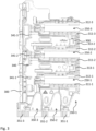
- Fig. 2 shows a view onto the switching device 1000 with the upper housing part 110 removed.
- the fuse holders 210-i are inserted into the housing 100 and are accommodated each in a respective fuse-receiving space 250-1, 250-2, 250-3 (hereafter sometimes collectively referred to as 250-i).
- the major part of the fuse-receiving spaces 250-i, as well as various other structures shown, are formed by an insulating intermediate part 300, made e.g. from a plastic material, which is at least in some parts bonded to the housing 100 via substance-to-substance bonding.
- the intermediate part 300 will be described. Since it is a preferred variant, mostly the case will be described that these portions of the intermediate part 300 are integrally formed with one another, i.e., with the entire intermediate part 300 itself.
- the entire intermediate part 300 may be produced by injection-molding.
- some portions of the intermediate part 300 may be formed separately, and may be arranged together later within the housing 100. They may be bonded together therein, preferably by substance-to-substance bonding.
- Each fuse-receiving space 250-i is bounded by a corresponding front wall portion 311-1, 311-2, 311-3 (hereafter sometimes collectively referred to as 311-i) of the intermediate part 300 in the direction towards the front side 103 of the housing 100, and by a corresponding rear wall portion 312-1, 312-2, 312-3 (hereafter sometimes collectively referred to as 312-i) in the direction towards the rear side 105 of the housing 100.
- the front wall portions 311-i and the rear wall portions 312-i are, preferably, all integrally formed with one another, either pairwise all over the entire switching device 1000.
- Fig. 2 also illustrates that the switching function of the switching device 1000 is provided by a shift linkage 400.
- the shift linkage 400 is accommodated such as to be movable along the longitudinal direction L.
- the electrical pathways are closed, i.e., the bottom-side electrical terminals 220-i are electrically connected to the front-side electrical terminals 230-i via the fuses inside the fuse holders 250-i.
- the electrical pathways run over respective switching bridges 410-1, 410-2, 410-3 (hereafter sometimes collectively referred to as 410-i) mounted to the shift linkage 400.
- the switching bridges 410-1, 410-2, 410-3 may be fixedly mounted to the shift linkage 400, or they may be movably mounted and pre-stressed by a spring.
- the shift linkage 400 is pre-loaded by one or more pre-loaded springs such as helical springs into a position with open electrical pathways, i.e., to the top of the page in Fig. 2 .
- pre-loaded springs such as helical springs
- actuating element 150 is actuated such that an actuating wheel 151 has been turned clock-wise.
- an actuating bar 152 Coupled to the actuating wheel 151 is an actuating bar 152, which is pressed towards the bottom side 109 of the housing 100 when the actuating wheel 151 is turned clockwise.
- a knee-type lever 153 is pivoted and pressed, past a dead point, against a curved nose 154 provided at the shift linkage 400, thus pressing the shift linkage 400 against its bias towards the front side 103 of the housing 100, thus closing the electrical pathways via the switching bridges 410-i.
- This mechanism is highly robust and is only released when the actuating element 150 is actuated again, allowing the actuating wheel 151 to turn counter-clockwise again.
- the shift linkage 400 is pushed towards the rear side 105 of the housing 100 by its at least one preloaded spring (preferably one preloaded spring close to each switching bridge 410-i), pulling the switching bridges 410-i away from their counterparts in the electrical pathways, thus opening the electrical pathways.
- a return spring may be provided which pushes the shift linkage 400 into its resting disconnected position after the contacts at the switching bridges 140-i have been opened.
- a further preloaded spring 155 for example a flat spring, may be provided.
- a desired hysteresis bias i.e. a force that has to be overcome to open the electrical pathways of the switching device 1000.
- the user only has to overcome a peak in the spring force, after which the switching-on of the switching device 1000 is performed without the user being able to halt it.
- the switching bridges 410-i contact, with surfaces oriented towards the front side 103 of the housing, on one side electrically conductive rails 221-1, 221-2, 221-3 connected to the bottom-side electrical terminals 220-i, and on another side electrically conductive rails connected to a respective base contact terminal for one of the fuse holder 250-i.
- the shift linkage 400 itself comprises a number of segmented sections 411-1, 411-2. From Fig. 2 it is evident that, when the shift linkage 400 is retracted, the segmented sections 411-1, 411-2 are brought closer to (preferably in overlap with) the electrically conductive rails 221-2 and 221-3, respectively, thus effectively widening the clearance distances and lengthening any creepage distances. Primarily, the segmented sections 411-1, 411-2 are interposed between each pair of consecutive switching bridges 410-i in order to increase the creepage distances between them, in particular when the switching device 1000 is switched on. Each segmented section 411-1, 411-2 comprises a plurality of segments between each two of which a respective groove is arranged that fully circles the circumference of the shift linkage 400 for increasing creepage distances.
- the shift linkage 400 itself is accommodated within a shift-linkage receiving portion 340 of the intermediate part 300, and a portion of the upper housing part 110, which will be described in more detail in the following.
- the switching device 1000 further comprises a locking mechanism 510-1, 510-2, 510-3 (hereafter sometimes collectively referred to as 510-i) for each front-side electrical terminal 230-i for locking the respective electrically conductive member 240-i thereto.
- each locking mechanism 510-i is accommodated in a corresponding locking-mechanism portion 350-1, 350-2, 350-3 (hereafter sometimes collectively referred to as 350-i) of the intermediate part 300.
- the locking-mechanism portions 350-i are integrally formed with one another, especially preferably also with the shift-linkage receiving portion 340 and/or with the frontmost front wall portion 311-1.
- Fig. 2 also illustrates, for the sake of completeness, two latching elements 222-1, 222-2 for releasably latching the switching device 1000 onto a touch-protecting grid of the busbar system (not shown) in order to provide additional grip.
- Fig. 3 shows the intermediate part 300 in the same orientation as in Fig. 2 , without any of the other elements and parts of the switching device 1000. It is evident how all of the described portions of the intermediate part 300 are formed integrally with one another. Apart from closing unwanted clearance distances, this also greatly facilitates assembly of the switching device 1000, as the intermediate part 300 can be inserted into the lower housing part 120 monolithically, and then be substance-to-substance bonded to the lower housing part 120 and/or the upper housing part 110 subsequently.
- Fig. 3 also clearly illustrates how preferably, in the two pairs of adjacent front wall portions and rear wall portions 312-1/311-2, 312-2/311-3, the respective rear wall portion 312-1, 312-2 is connected to the respective front wall portion 311-2, 311-3 via a corresponding top-side ribbed portion 313-1, 313-2 (hereafter sometimes collectively referred to as 313-i) of the intermediate part 300.
- the top-side ribbed portions 313-i connect top-side ends of the front wall portions 311-2, 311-3 and the rear wall portions 312-1, 312-2, and comprise (or consist of) ribs protruding towards the top side 101 of the housing 100 (i.e. to the right in Fig. 3 ). These ribs function to increase creepage distances between the fuse-receiving spaces 250-1 and 250-2, or 250-2 and 250-3, respectively.
- Fig. 3 further illustrates that the shift-link receiving portion 340 of the intermediate part 300 comprises at least one ribbed section, here three ribbed sections 341-1, 341-2, 341-3 (hereafter sometimes collectively referred to as 341-i).
- the first ribbed section 341-1 is arranged such that its ribs protrude towards the front side 103 of the housing 100.
- said first ribbed section 341-1 is adapted, and closely adheres (with or without touching) to the electrically conducting rail 221-1 connected to a first of the bottom-side electrical terminals 220-1.
- ribs (here: two ribs) extend in parallel to the width W of the switching device 1000 and protrude away from the contact point between the electrically conducting rail 221-1 and a first switching bridge 410-1.
- the main function of the ribbed sections 341-i is to receive and disperse forces exerted by the switching bridges 410-i and/or the shift linkage 400.
- the two other ribbed sections 341-2, 341-3 are arranged adjacent to electrically conducting rails 221-2, 221-3 of second and third bottom-side electrical terminals 220-2, 220-3, respectively (see Fig. 2 ).
- their ribs here: five ribs each
- their ribs extent parallel to the width W but protrude towards the shift linkage 400, and also protrude in parallel to the surfaces of the electrically conducting rails 221-i and the bridging elements 410-i configured to touch when the switching device 1000 is in the closed state.
- Fig. 2 also illustrates that the ribbed sections 341-2, 341-3 in each state of the switching device 1000 at least partially overlap, along the longitudinal direction L, with the segmented sections 411-1, 411-2, of the shift linkage 400, thus creating a labyrinth of increased creepage distances and close clearance distances.
- a length of the segments of the segmented sections 411-1, 411-2 in the longitudinal direction L may be equal to a length of the distance between two adjacent ribs of the ribbed sections 341-2, 341-3.
- Fig. 2 and especially Fig. 3 also illustrate that the intermediate part 300 may further be formed with front-side ribbed portions 351-1, 351-2, 351-3 (hereafter sometimes collectively referred to as 351-i), which further increase creepage distances.
- the front-side ribbed portions 351-i are preferably formed integrally with the locking-mechanism portions 350-i.
- FIG. 4 shows a slightly rotated 3-dimensional view of the intermediate part 300, with a few additional elements of the switching device 1000 shown to explain how the fuses are contacted.
- each of the fuse-receiving spaces 250-i has been selected to show different parts; it shall be understood, however, that, as is evident e.g. from Fig. 2 , in reality all of the fuse-receiving spaces 250-i will comprise all of these parts.
- Shown in the first fuse-receiving space 250-1 is a first base contact terminal 261-1 for contacting a first terminal of the fuse when it is inserted into the fuse holder 210-1 and the fuse holder 210-1 is inserted into the fuse-receiving space 250-1.
- the first base contact 261-1 is integrally formed with a tab 262-1 that is substantially arranged at a right angle to the first base contact 261-1. This tab 262-1 provides a surface for the bridging element 410-1 to connect to when the switching device 1000 is in the closed state.
- the tab 262-1 and the first base contact 261-1 are part of an electrically conducting rail that electrically connects the bridging element 410-1 to the fuse in the first fuse-receiving space 250-1.
- the fuse holder 210-1 For contacting the other terminal of the fuse, the fuse holder 210-1 comprises a crown contact terminal 269-1 that is integrally formed with a tab guided through the first front wall portion 311-1, thus continuing the electrical pathway from the first bottom-side electrical terminal 220-1 to the first front-side electrical terminal 230-1.
- a base contact spring plunger 263-2 is provided (here shown only in the second fuse-receiving space 250-2).
- This base contact spring plunger 263-2 in turn is biased by a base contact spring element 264-3 (here only shown in the third fuse-receiving space 250-3).
- the pre-biased (or: pre-loaded) base contact spring plunger 263-2 is also advantageous, because the length of the fuses is subject to tolerances, requiring some play between the base contact terminal 261-i and the crown contact terminal 269-i of each fuse.
- Fig. 4 also illustrates that the front wall portions 311-i and/or the rear wall portions 312-i may be provided with ribbed structures 315-1, 315-2, 315-3, 316-1, 316-2 on their respective outer side, the outer side meaning a side oriented away from the fuse-receiving space 250-i bounded by the respective front wall portion 311-i or rear wall portion 312-i.
- the ribbed structures 315-1, 315-2, 315-3, 316-1, 316-2 mainly serve to stabilize the fuse-receiving spaces 250-i.
- the ribbed structures 315-1, 315-2, 315-3 (hereafter sometimes collectively referred to as 315-i) of the front wall portions 311-i are each provided with six ribs extending along the width W direction of the switching device 1000 and protruding towards the front side 103 of the housing 100.
- the ribbed structures 316-1, 316-2 of the first and second rear wall portion 312-1, 312-2 each are shown here with four ribs extending along the width W direction and protruding towards the rear side 105 of the housing 100.
- Fig. 4 also shows that in the spaces between two fuse-receiving spaces 250-i, the rear wall portion 312-1, 312-2 of the preceding (along the longitudinal direction L) fuse-receiving space 250-1, 250-2 is connected to the front wall portion 311-2, 311-3 of the following (along the longitudinal direction L) fuse-receiving space 250-2, 250-3 by a (substantially strip-shaped) plate portion 319-1, 319-2 of the intermediate part 300.
- Each plate portion 319-1, 319-2 extends substantially perpendicularly to the rear wall 312-i portions and the front wall portions 311-i, i.e., their planes lie parallel to the longitudinal direction L and to the depth D direction, and perpendicular to the width W direction.
- the plate portions 319-1, 319-2 connect the adjacent front wall portion 311-i and rear wall portion 312-i and are preferably integrally formed with them.
- the plate portions 319-1, 319-2 are arranged substantially (+/-20%) or exactly at the center, in width W direction, of the intermediate part 300, and separate the spaces between the fuse-receiving spaces 250-i in the width W direction into (locally) two separate chambers: an upper chamber 117 (visible in Fig. 4 ) oriented towards the upper housing part 110 and a lower chamber 127 (visible in Fig. 5 ) oriented towards the lower housing part 120.
- the lower chamber 127 is used to accommodate further electrically conducting rails for connecting the crown contact terminal 269-i to the front-side electrical terminals 230-i.
- the plate portions 319-1, 319-2 thus close (or at least increase) clearance distances around these further electrically conducting rails.
- the plate portions 319-1, 319-2 are all integrally formed, and joined to, the shift-linkage receiving portion 340 of the intermediate part 300, in particular to a lower-housing-part-side wall 349 of the shift-linkage receiving portion 340.
- This wall 349 preferably closes the entirety of the shift-linkage receiving portion 340 against the lower chamber 127 and is coplanar with the plate portions 319-1, 319-2.
- the wall 349 extends all the way from the third locking-mechanism portion 350-3 to the rear side 105 of the switching device 1000, forming an essentially (or completely) unbroken dividing wall between the upper chamber 117 and the lower chamber 127.
- Fig. 5 shows a slightly rotated, 3-dimensional view of the intermediate part 300 from the other side as compared to Fig. 4 , i.e., from the side of the lower housing part 120.
- the outer sides of the front wall portions 311-i and the rear wall portions 312-i in the lower chamber 127 may comprise ribbed structures 317-i which may essentially or exactly mirror the ribbed structures 315-i in the upper chamber (i.e. between the intermediate part 300 and the upper housing part 110), wherein the plate portions 319-1 may act as mirror planes.
- the front wall portions 311-i in the shown embodiment further comprise, in the lower chamber 127, ventilation openings 318-i which enable heat convection within the housing 100 (specifically the lower chamber 127) and, eventually, to the outside.
- Fig. 5 also shows that the shift-linkage receiving portion 340 of the intermediate part 300 is contributing in separating the space between the upper housing part 110 and the lower housing part 120 into the upper chamber 117 and the lower chamber 127, being integrally formed with the plate portion 319-1, 319-2.
- the shift-linkage receiving portion 340 and the plate portions 319-1, 319-2 cover about at least 50% of the L-D-cross-section of the housing 100 (i.e. the cross section parallel to both the longitudinal direction L and the depth D direction).
- the plate portions 319-1, 319-2 and the shift-linkage receiving portion 340 form rail-guiding portions 321-2, 321-3 of the intermediate part 300, which are configured to accommodate electrically conducting rails leading 271-2, 271-3 (shown only schematically as dashed lines in Fig. 5 ) from the crown contact elements 291-1 to the respective front-side electrical terminals 230-i.
- the rail-guiding portions 321-2, 321-3 at least partially encompass said electrically conducting rails 271-2, 271-3 on three sides, wherein the fourth side may be closed by the lower housing part 120.
- Fig. 6 shows a schematic view of some interior elements of the switching device 1000, seen from the top side 101 of the housing 100.
- the dashed line in the middle represents where the intermediate part 300 (not shown in Fig. 6 ) would separate the upper chamber 117 inside the housing 100 from the lower chamber 127 inside the housing.
- Fig. 6 also serves to illustrate how the electrically conducting rails 271-i end in contact ends 272-1, 272-2, 272-3 (hereafter sometimes collectively referred to as 272-i) for contacting the corresponding tabs of the corresponding crown contact terminal 269-1.
- the ends may be borne slightly movably or pivotably, and a corresponding spring member 273-1, 273-2, 273-3 (hereafter sometimes collectively referred to as 273-i) may be provided for biasing the respective contact end 273-i towards the tab of the respective crown contact terminal 269-1.
- Fig. 7 shows a schematic side view of some interior elements of the switching device 1000 from the view of the lower housing part 120.
- Fig. 7 is complementary to Fig. 5 , since they show, from the same perspective, the intermediate part 300 ( Fig. 5 ) without surrounding elements, and the surrounding elements ( Fig. 7 ) without the intermediate part 300.
- Fig. 7 illustrates the complete electrical pathways from the bottom-side electrical terminals 220-i to the front-side electrical terminals 230-i: starting from the bottom-side electrical terminal 220-i itself, over the electrically conducting rail 221-i, to the bridging element 410-i, from there to the tabs 262-i of the base contact terminal 261-i and the base contact terminal 261-i itself, then to the first terminal of the fuse 270-1, 270-2, 270-3 (hereafter sometimes collectively referred to as 270-i), into the crown contact terminal 269-1, 269-2, 269-3 (hereafter sometimes collectively referred to as 269-i) and its respective tab 274-1, 274-2, 274-3 (hereafter sometimes collectively referred to as 274-i); from there via the contact end 272-i into the electrically conducting rail 271-i and finally to the front-side electrical terminal 230-i.
- Fig. 8 shows a selection of elements of the switching device 1000 for illustrating how external electrically conductive elements 240-i are inserted, electrically contacted, fixed, and released in the switching device 1000.
- Each of the locking mechanisms 510-i comprises, to this end, a locking actuator 520-1 and a locking flat spring 530-1.
- a locking actuator 520-1 accommodated in the first locking-mechanism portion 350-1, is shown, it shall be understood that all feature described with respect to it equally apply to other locking actuators 520-2, 520-3 for the other locking-mechanism portions 350-2, 350-3.
- the main element effecting the strong electrical and mechanical connection is the respective locking flat spring 530-i.
- the third locking flat spring 530-3 is shown schematically as it would be shaped without an external electrically conductive element 240-3 being inserted and without any locking actuator 520-3.
- the second locking flat spring 530-2 is shown in a constricted state, with the second external electrically conductive element 240-2 being inserted and held.
- the interaction an mutual engagement between the elements of the first locking mechanism 510-1 are shown.
- Fig. 9 shows a schematic close-up of the shape of each locking flat spring 530-i.
- the locking flat spring 530-i is generally a flat strip formed in a closed loop: its first end 531-i comprises a window 532-i that is bounded, at the very tip of the first end 531-i, by a bar member 533-i.
- the first end 531-i is connected, after a first extremal point 534-i, to a first arm 535-i of the locking flat spring 530-i.
- the first arm 535-i flows into a second arm 537-i which ends in a second end 539-i of the locking flat spring 530-i.
- the second end 539-i is provided with a protruding tab 538-i.
- the bends of the locking flat spring 530-i at the first extremal point 534-i and the second extremal point 536-i cause an outward-directed force that presses the protruding tab 538-i against the bar member 533-i.
- the locking flat spring 530-i can be generally described as bent into a triangle shape, with the three sides being the first end 531-i with the window 532-i, the first arm 535-i, and the second arm 537-i, and the three angles being the first extremal point 534-i (a rounded angle), the second extremal point 536-i (another rounded angle) and the point where the protruding tab 538-i and the bar member 533-i meet.
- Inserting the external electrically conductive element 240-i will now be described by way of the second locking flat spring 530-2 and the second external electrically conductive element 240-2.
- the window 532-2 in order to insert the external electrically conductive element 240-i into the window 532-2 of the second locking flat spring 530-2, the window 532-2 must be moved so that a larger portion thereof is on the other side of the electrically conducting rail 271-2. To achieve this, a force towards the electrically conducting rail 271-2 must be applied to the first arm 535-2 (towards the right-hand side of Fig. 8 ). This is accomplished by way of the locking actuator 520-i, as will be described in the following.
- Fig. 8 also shows that the intermediate part 300 has three small nooks 352-i into which the bar members 533-i of the locking flat springs 530-i go and which stop any further movement of the bar members 533-i, when the window 532-i is pushed to open (i.e., to the right).
- the intermediate part 300 also provides a respective abutment against which each locking flat spring 530-i rests.
- the intermediate part 300 further provides for at least one locking flat spring 530-i (here: for the second and the third locking flat spring 530-2, 530-3) a respective protrusion 354-2, 354-3 within the locking-mechanism portion 350-i against which the tip of the respective hook-shaped portion 279-i can rest.
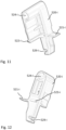
- Fig. 10 illustrates the functioning of the locking actuator 520-i, using again the first locking actuator 520-1 and the second locking actuator 520-2 as examples.
- the shape of the locking actuators 520-i is shown in Fig. 11 and Fig. 12 from two different perspectives.
- the shape of the locking actuators 520-i closely corresponds to the inside shape of the upper housing part 110 and the inside shape of the lower housing part 120 in the area of the locking actuators 520-i.
- Each locking actuator 520-i comprises a bore 524-i into which one or more parts of a corresponding axle will be inserted from one or both sides to allow a pivoting movement.
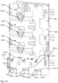
- Fig. 13 illustrates the inside of the upper housing part 110 of the housing 100 of the switching device 1000
- Fig. 14 illustrates the inside of the lower housing part 120 of the housing 100 of the switching device 1000.
- the locking-mechanism portion 350-i is shaped such that the locking actuator 520-i therein can pivot around a respective pivoting axis 140-i.
- the corresponding axles 141-i for this pivoting movement are formed, in the shown embodiment, both partially (e.g., half) in the upper housing part 110 (see Fig. 13 ) and partially (e.g., half) in the lower housing part 120 (see Fig. 14 ), although other variants are also possible, depending, for example, on the manufacturing method.
- the second and third locking-mechanism portions 350-2, 350-3 are formed essentially with an asymmetrical bell shape, wherein the locking actuator 520-i can rest against either arm of the bell shape in its extreme pivoted positions.
- Each locking actuator 520-i and the corresponding axle 141-i are shaped such that there is a predefined amount of play so that the locking actuator 520-i can move into an eccentric position with regard to the pivoting axis 140-i.
- the first locking actuator 520-1 is shown in a latched position in which the corresponding locking flat spring 530-1 is pressed so as to allow inserting or releasing the external electrically conductive element 240-1.
- the second locking actuator 520-2 is shown in a relaxed position, in which the locking flat spring 530-2 is not, or minimally, pressed by the locking actuator 520-2 and thus its bar member 533-2 strongly pulls the external electrically conductive element 240-2 against the electrically conducting rail 271-2.
- each locking actuator 520-i has its protruding nose tab 521-i: a flat tab protruding essentially perpendicularly from the main body of the locking actuator 520-i.
- the nose tab 521-i is best visible in Fig. 11 .
- the entire locking actuator 520-i is made integrally (or: monolithically), from a plastic material having a predefined degree of elasticity.
- the nose tab 521-i can be slightly bent without breaking, and exerts a force acting towards returning to the unbent shape when bent.
- all of the locking-mechanism portions 350-i of the intermediate part 300 are provided with a recess structure 355-i.
- the recess structure 355-i is deep enough and wide enough (in the width W direction of the switching device 1000) to receive the nose tab 521-i when the locking actuator 520-i is in the latched position, as shown in Fig. 10 for the first locking actuator 520-1.
- the recess structure 355-i comprises, or consist of, two sections: 1) a mouth section 356-i, which ends in 2) a latching section 357-i.
- the cross-section of the mouth section 356-i decreases from its opening (into the locking-mechanism portion 350-i) towards the latching section 357-i.
- the latching section 357-i has a latching wall 358-i, which is angled such that when the locking actuator 520-i is pivoted towards the recess structure 355-i, the nose tab 521-i must necessarily be bent towards the front side 101 of the housing for the locking actuator 520-i to finish its pivoting movement to end up in the latched position, with the tip of the nose tab 521-i resting against the latching wall 358-i.
- the elastic force exerted by the bent nose tab 521-i pushes (or pulls) the locking actuator 520-i into a (slightly) eccentric position, as is shown for the first locking actuator 520-1 in Fig. 10 .
- Eccentric in this context may be understood to mean that a rotational center of the locking actuator 520-i (e.g., a rotational center of the bore 524-i), which coincides with the pivoting axis 140-i during the relaxed position, does no longer coincide with the pivoting axis 140-i in the eccentric position.
- the locking actuator 520-i will no longer exactly align with the top of the bell shape of the locking-mechanism portions 350-i.
- each locking actuator 520-i On both of its outsides in the width W direction, each locking actuator 520-i is formed with latching protrusions.
- Fig. 11 shows a upper-side latching protrusion 522-i, which is facing the upper housing part 110
- Fig. 12 shows a (larger) lower-side latching protrusion 523-i, which is facing the lower housing part 120.
- Both latching protrusions 522-i, 523-i are essentially oblongshaped, wherein the long sides of said oblong may have a defined curvature.
- the upper housing part 110 is formed with a upper-side latching contour 112-i for the corresponding upper-side latching protrusion 522-i of each of the locking actuators 520-i (see Fig. 13 ), and the lower housing part 120 is formed with a lower-side latching contour 123-i for the corresponding lower-side latching protrusion 523-i of each of the locking actuators 520-i.
- the upper-side latching contours 112-i and the lower-side latching contours 123-i each are formed (generally or exactly) in the shape of a hatchet, with the head (or blade) portion of the hatchet oriented towards the bottom side 109.
- the upper-side latching contours 112-i each comprise a first (or: handle) portion 114-i and a second (or: head) portion 116-i, which are separated by a step 115-i in between.
- the lower-side latching contours 123-i each comprise a first (or: handle) portion 124-i and a second (or: head) portion 115-i, which are separated by a step 114-i in between.
- any locking actuator 520-i When any locking actuator 520-i is in the relaxed position (shown for the second locking actuator 520-2 in Fig. 10 ), then both its upper-side latching protrusion 522-i and its lower-side latching protrusion 523-i will abut against the first (or: handle) portions 114-i, 124-i of the corresponding upper-side latching contour 112-i and the corresponding lower-side latching contour 123-i.
- the first (or: handle) portions 114-i, 124-i thus preferably have the same defined curvature as the latching protrusions 522-i, 523-i, preferably corresponding to a circle section with respect to the pivoting movement's pivoting axis 140-i.
- the latching protrusions 522-i, 523-i will move towards the second (or: head) portion 116-i, 126-i of the latching contours.
- the nose tab 521-i of the locking actuator 520-i will engage the latching wall 538-i such that the locking actuator 520-i will be pushed towards the front side 103 of the housing 100. This point corresponds with a position in which the latching protrusions 522-i, 523-i have left the first (or: handle) portions 114-i.
- the locking actuator 520-i will be in the latched position (shown for the first locking actuator 520-1 in Fig. 10 ): although its corresponding locking flat spring 530-i will push to reverse the pivoting movement, the latching protrusions 522-i, 523-i are caught (or: latched) behind the steps 115-i, 125-i of the latching contours 112-i, 123-i.
- the locking actuator 520-i would have to be pushed in, i.e., towards the rear side 105 of the housing 100. In the locked state, this is prevented by the force exerted on the locking actuator 520-i by the bent nose tab 521-i.
- a user has to push the locking actuator 520-i inside, back to its centered (i.e., non-eccentric) position with respect to the pivoting axis 140-i, enough so that the latching protrusions 522-i, 523-i overcome the steps 115-i, 125-i in the latching contours 112-i, 123-i.
- This push has to be done against further resistance by the bent nose tab 521-i; preferably, the nose tabs 521-i and the latching wall 538-i are designed such that this can be done without any tools but must be done deliberately.
- each locking actuator 520-i is provided with an actuating groove 529-i.
- the actuating groove 529-i is arranged at a front-side end of the locking actuator 520-i, i.e., an end of each locking actuator 520-i which protrudes from the front side 103 of the housing 100.
- the actuating groove 529-i is oriented as open towards the top side 101 of the housing and is part of the section of the locking actuator 520-i protruding from the housing 100.
- the front side 101 of the housing 100 is the side that provides all necessary accesses to a user when the switching device 1000 is mounted at its bottom side 109 to a busbar system: the front side 101 gives access to the fuse holders 210-i and to the actuating grooves 529-i as well.
- a user wishing to retrieve the external electrically conductive element 240-2 from the switching device 1000 may insert the tip of a tool (e.g., a screwdriver) into the actuating groove 529-2 of the second locking actuator 520-2 and thus push and pivot the second locking actuator 520-2 into its latched position.
- a tool e.g., a screwdriver
- the first arm 535-i of the locking flat spring 530-i is pressed towards the second arm 537-i, and the window 532-i is maximally opened with the bar member 533-i being closest to, or even entered into, the nook 352-i. This allows easy insertion or retrieval of the external electrically conductive element 240-i.
- Fig. 13 incidentally also illustrates a part of the ventilation concept of the present invention, showing a plurality of (here: three) ventilation intakes 118-1, 118-2, 118-3 (hereafter sometimes collectively referred to as 118-i) within the upper housing part 110 for each fuse-receiving space 250-i, and a plurality of (here: three) ventilation exhausts 119-i for each fuse-receiving space 250-i.
- the corresponding outside view of the intakes 118-i and the exhausts 119-i in the upper housing part 110 is provided by Fig. 1 .
- the ventilation exhausts 119-i may be formed as a jutty structure (reaching into the housing), e.g. as a triangular jutty structure 119-3 or as an oblong jutty structure 119-1, 119-2.
- a central one (with respect to the width W direction) is formed larger than the others in the longitudinal direction L and partially overlaps with the corresponding fuse-receiving space 250-i, in particular where, as is shown later in Fig. 18 , the fuse holder 210-i exposes a portion of the fuse 170-i.
- Fig. 14 also shows ventilation openings 128-1, 128-2, 128-3 (hereafter sometimes collectively referred to as 128-i) within the lower housing part 120 that may be formed identically to the ventilation intakes 118-i in the upper housing part 110 (see Fig. 13 ).
- Fig. 14 in addition illustrates guiding portions 121-1, 121-2, 121-3 (hereafter sometimes collectively referred to as 121-i) of the lower housing part 120 which are configured to conform to, and engage with, the rail-guiding portions 321-i of the intermediate part 300 (compare with Fig. 5 ).
- Fig. 15 shows the front side 103 of the housing 100 in the exemplary embodiment of Fig. 1 through 10 .
- Fig. 10 in particular illustrates how the front side 103 of the housing 100 is formed in part by the upper housing part 110, in part by the lower housing part 120, and in part by a front-side portion of the intermediate part 300, the front-side portion of the intermediate part 300 being sandwiched between the upper housing part 110 and the lower housing part 120.
- the front-side openings 129-i are each also formed partially (here, for the majority) by the intermediate part 300, and partially by the lower housing part 120.
- the bottom-side electrical terminal 220-1 can be seen (the others are exactly behind it in line along the longitudinal direction L), formed as a once-folded-over, V-shaped tongue configured to be inserted into a slit in a slitted busbar or a slit in a hybrid busbar.
- a respective mechanical plug 223-1 is provided, distanced by the bottom-side electrical terminal 220-1 by exactly the same slit interval SI.
- Fig. 10 also illustrates that the width W of the switching device 1000 corresponds to about (or exactly) five times the slit interval SI so that a plurality of switching devices 1000 can be arranged adjacently, in the width W direction, along the busbar, without any dead space in between.
- the shown embodiment in particular with respect to the form of the bottom-side electrical terminals 220-i and the mechanical plugs 223-1, is compatible with slitted busbars or hybrid busbars (which comprise both a current-carrying profile portion and a slitted profile portion).
- the switching device 1000 may also be configured to be compatible with other types of busbars, for example solid busbars.
- the bottom-side electrical terminals would typically comprise contact elements contacting a front surface (with respect to the switching device 1000) of the solid busbar.
- electrical and/or mechanical hook-shaped elements may be provided for gripping edges of the solid busbar, so that the switching device 1000 may, for example, be hung from the solid busbars at the hook-shaped elements.
- the hook-shaped elements may be formed as electrically conducting, so as to provide, in addition to mechanical stability, also an additional electrical contact on the edge and/or the rear surface (with respect to the switching device 1000) of the solid busbar.
- Fig. 16 shows a three-dimensional view illustrating mainly the bottom side 109 of the housing 100 in the exemplary embodiment of Fig. 1 through 10 . It shows how the bottom side 109 is mainly formed by the lower housing part 120, and only to a smaller degree by parts of the upper housing part 110, the intermediate part 300, and the optional side housing part 130.
- the intermediate part 300 is preferably made from a plastic material that conducts heat well, it also acts as a cooling member: it is in contact, for example via the rail-guiding portions 321-i for the electrically conducting rails 271-i (and similar rail-guiding portions for the electrically conducting rails 221-i) with many of the parts in which the most heat develops when the switching device 1000 is in use. Due to its heat-conducting properties, the intermediate part 300 thus transports heat from inside of the housing towards its various ribbed structures. For example, at the front side 103 of the housing, the front-side ribbed portions 351-i help to radiate heat away from the switching device 1000.
- the part of the intermediate part 300 at the outside of the bottom side 109 of the housing 100 may be provided with a bottom-side ribbed portion 359.
- the various ribbed sections of the intermediate part 300 at the inside of the housing 100 also function to radiate heat, heating up air inside the housing 100, which may then freely escape through ventilation slits as can be seen, for example, in Fig. 1 in the upper housing part 110.
- the intermediate part 300 advantageously provides guiding, cooling, insulating, bearing, and many other functions to the switching device 1000.
- Fig. 17 shows a detail of the top side 101 of the housing 100 of the switching device 1000, without the side housing part 130.
- side housing latches 139 are provided for latching the side housing part 130 thereto.
- the view in Fig. 15 is centered around a fuse holder opening 280-i therein, leading to a corresponding one of the fuse-receiving spaces 250-i.
- Fig. 17 also illustrates how the walls encasing the fuse holders 210-i within the fuse-receiving space 250-i are formed jointly by the upper housing part 110, the intermediate part 300, and the lower housing part 120. Wherever two different parts 110, 120, 300 meet, they may be substance-to-substance bonded there, in particular welded using ultrasound plastic welding, or glued. On the side of the intermediate part 300, it is particularly the front wall portions 311-i and the rear wall portions 312-i that contribute.
- the upper housing part 110 and the lower housing part 120 are also formed with latching teeth 281.
- the upper housing part 110 and the lower housing part 120 may also comprise recesses 282 of the outer contour of the fuse holder opening 280-i at the front side 101, which may otherwise be circular in shape.
- the fuse holders 210-i are inserted in the axial direction A (see Fig. 4 ) into the fuse-receiving spaces 250-i, at an angle (with respect to a rotation around said axial direction) to a position in which they will be at rest and operational within the fuse-receiving spaces 250-i.
- This angle is between 10° and 90°, preferably between 20° and 70°, more preferably between 30° and 60°, for example 35°.
- the intermediate part 300 may be provided with a guiding groove 370-i, arranged in parallel to the axial direction A within each of the fuse-receiving spaces 250-i, for guiding the movement of the fuse holder 210-i along the axial direction A.
- Fig. 18 shows a 3-dimensional view of a fuse holder 210-i with a cylindrical fuse 170-i arranged therein. It illustrates how the fuse holder 210-i may be provided with at least one guiding protrusion 283 configured for insertion into the guiding groove 370-i of the intermediate part 300.
- Fig. 19 shows a schematic view of an interior of the side housing part 130 in a variant. Specifically, Fig. 19 shows the switching device 1000 from the side of the side housing part 130, however, with the side housing part 130 itself removed, offering a view of its interior.
- the switching device 1000 is provided with a motorized actuator for the switching function.
- the switching function can thus be remotely controlled.
- the switching device 1000 may comprise a communications interface for receiving switching signals for switching the switching device 1000.
- the motorized actuator may be provided in addition or instead of the (manual) actuating element 150 as described in the foregoing. Preferably, both are provided, such that a user may always switch the switching device 1000 off in case of an emergency.
- the motorized actuator may be configured to turn the actuating wheel 151.
- a linear motor 131 is provided within the housing side part 130. It is configured to linearly move a shaft 132 (e.g., a threaded shaft), which in turn engages a gearbox.
- the gearbox comprises a first moving gear part 133 and a second moving gear part 134.
- the first moving gear part is actuated by the linearly moving shaft 132, translating (and leveraging) the linear force into a rotational movement of gear teeth; the second moving gear part 134 receives the rotational movement via its own teeth and translates it to a rotational movement of the actuating wheel 151 (see Fig. 2 ).
- the gearbox is provided with enough play such that a user may manually activate the (manual) actuating element 150, for example in case of an emergency.
- the linear motor 131 may be controlled via electronic components within the side housing part 130, which may be arranged on, or controlled and/or connected by, a printed circuit board 135 arranged within the side housing part 130.
- the printed circuit board 135 preferably has a communications interface for communication with an external transceiver, for example via a communications field bus.
- the printed circuit board 135 may be configured to receive switching signals for switching the switching device 1000, i.e., control signals for the motorized actuator (here: linear motor 131).
- the printed circuit board 135 may also have other functions. For example, it may provide monitoring functions of the switching device 1000, transmit monitoring data over the communications interface, and/or the like.
- the width of the switching device 1000 may be larger than in other variants, although the present invention still enables the switching device 1000 to have, ceteris paribus, a much smaller width W than hypothetical comparable switching devices.
- the width W may be 49,5 mm, 49,2 mm, or less.
- a nominal width of 49,5 mm would, for example, correspond to 11 times the slit interval SI of 4,5mm in one possible variant of a slitted busbar or a hybrid busbar.
- the switching device 1000 may be formed with a width of 49,2mm, for example, to ensure that an adjacent device can be coupled to the same slitted or hybrid busbar without losing a full slit interval SI.
- Fig. 20 shows a schematic flow diagram illustrating a method according to the second aspect of the present invention, i.e. of a method for manufacturing the switching device 1000.
- manufacturing the switching device 1000 may comprise a step S100 of providing (e.g., manufacturing) the upper housing part 110, a step S200 of providing (e.g., manufacturing) the lower housing part 120, and a step S300 of providing (e.g., manufacturing) the intermediate part 300.
- steps S100, S200, S300 may be performed, for example, via injection molding.
- a step S400 the remaining parts of the switching device 1000 are inserted into the housing 100 and/or connected or coupled with the upper housing part 110, the lower housing part 120 and/or the intermediate part 300.
- a substance-to-substance bonding is performed, of the intermediate part 300 to the lower housing part 110 and/or to the lower housing part 120, either consecutively or concurrently.
- glue may be applied to any of the three parts, and then they may be put together in their final configuration, letting the glue solidify.
- welding is used for the substance-to-substance bonding, however.
- the intermediate part 300 may be welded to either the upper housing part 110 or the lower housing part 120, and then to the respective other part.
- the welding may comprise ultrasound plastic welding and/or laser welding and/or hot plate welding.
Landscapes
- Fuses (AREA)
- Switch Cases, Indication, And Locking (AREA)
Priority Applications (3)
| Application Number | Priority Date | Filing Date | Title |
|---|---|---|---|
| EP23209559.6A EP4553882A1 (fr) | 2023-11-13 | 2023-11-13 | Dispositif de commutation pour un système de barre omnibus |
| PCT/EP2024/082269 WO2025104135A1 (fr) | 2023-11-13 | 2024-11-13 | Dispositif de commutation pour système de barre omnibus |
| PCT/EP2024/082270 WO2025104136A1 (fr) | 2023-11-13 | 2024-11-13 | Dispositif de commutation pour système de barre omnibus |
Applications Claiming Priority (1)
| Application Number | Priority Date | Filing Date | Title |
|---|---|---|---|
| EP23209559.6A EP4553882A1 (fr) | 2023-11-13 | 2023-11-13 | Dispositif de commutation pour un système de barre omnibus |
Publications (1)
| Publication Number | Publication Date |
|---|---|
| EP4553882A1 true EP4553882A1 (fr) | 2025-05-14 |
Family
ID=88833840
Family Applications (1)
| Application Number | Title | Priority Date | Filing Date |
|---|---|---|---|
| EP23209559.6A Withdrawn EP4553882A1 (fr) | 2023-11-13 | 2023-11-13 | Dispositif de commutation pour un système de barre omnibus |
Country Status (2)
| Country | Link |
|---|---|
| EP (1) | EP4553882A1 (fr) |
| WO (2) | WO2025104135A1 (fr) |
Citations (4)
| Publication number | Priority date | Publication date | Assignee | Title |
|---|---|---|---|---|
| WO2014017265A1 (fr) * | 2012-07-23 | 2014-01-30 | 矢崎総業株式会社 | Unité de fusibles |
| CN115548532A (zh) * | 2021-06-30 | 2022-12-30 | 罗伯特·博世有限公司 | 蓄电池组 |
| US20230156967A1 (en) * | 2020-05-21 | 2023-05-18 | Autonetworks Technologies, Ltd. | Circuit assembly |
| CN116547775A (zh) * | 2020-11-20 | 2023-08-04 | 维纳尔产业有限公司 | 熔断器保持器 |
Family Cites Families (4)
| Publication number | Priority date | Publication date | Assignee | Title |
|---|---|---|---|---|
| US2509471A (en) * | 1947-04-30 | 1950-05-30 | Honeywell Regulator Co | Control apparatus |
| US8614618B2 (en) * | 2004-09-13 | 2013-12-24 | Cooper Technologies Company | Fusible switching disconnect modules and devices with multi-functional trip mechanism |
| FR2904470B1 (fr) * | 2006-07-31 | 2008-11-07 | Areva T & D Sa | Dispositif de commande d'un appareillage electrique moyenne ou haute tension et procede de commande d'un dispositif de commande d'un appareillage electrique moyenne ou haute tension |
| CN106356263B (zh) * | 2016-11-29 | 2018-10-23 | 浙江中富电气有限公司 | 一种断路器的自动重合闸装置 |
-
2023
- 2023-11-13 EP EP23209559.6A patent/EP4553882A1/fr not_active Withdrawn
-
2024
- 2024-11-13 WO PCT/EP2024/082269 patent/WO2025104135A1/fr active Pending
- 2024-11-13 WO PCT/EP2024/082270 patent/WO2025104136A1/fr active Pending
Patent Citations (4)
| Publication number | Priority date | Publication date | Assignee | Title |
|---|---|---|---|---|
| WO2014017265A1 (fr) * | 2012-07-23 | 2014-01-30 | 矢崎総業株式会社 | Unité de fusibles |
| US20230156967A1 (en) * | 2020-05-21 | 2023-05-18 | Autonetworks Technologies, Ltd. | Circuit assembly |
| CN116547775A (zh) * | 2020-11-20 | 2023-08-04 | 维纳尔产业有限公司 | 熔断器保持器 |
| CN115548532A (zh) * | 2021-06-30 | 2022-12-30 | 罗伯特·博世有限公司 | 蓄电池组 |
Also Published As
| Publication number | Publication date |
|---|---|
| WO2025104135A1 (fr) | 2025-05-22 |
| WO2025104136A1 (fr) | 2025-05-22 |
Similar Documents
| Publication | Publication Date | Title |
|---|---|---|
| US7527509B1 (en) | Electrical disconnect with push-in connectors | |
| US8262405B1 (en) | Wire-to-wire connector | |
| JP5185347B2 (ja) | 電力接点およびこれを有するコネクタ | |
| US20170363818A1 (en) | Plug connector | |
| CN101015096A (zh) | 可反转通用串行总线(usb)装置和连接器 | |
| EP1737070A2 (fr) | Connecteur électrique avec contacts enfilables | |
| JP2022002217A (ja) | 電池パック用輸送システム | |
| CN105703120B (zh) | 堆叠式弹簧端子 | |
| EP4553882A1 (fr) | Dispositif de commutation pour un système de barre omnibus | |
| US20140370731A1 (en) | Electric coupling element | |
| JPH1186831A (ja) | バッテリーの接続構造 | |
| US6494727B2 (en) | Positioning mechanism of foldable plug and structure of connector having the same | |
| US4857016A (en) | Components for flexible wiring systems | |
| CN111355050B (zh) | 隔离端子 | |
| CN1902789B (zh) | 电源触头及包括电源触头的连接器 | |
| US20030057081A1 (en) | Contact block assembly and a method of assembling a contact block assembly | |
| US7438575B2 (en) | Electrical connector | |
| EP4040604A1 (fr) | Systèmes et procédés pour un connecteur de câble | |
| CN216133772U (zh) | 一种小型断路器的操作机构 | |
| CN101640147B (zh) | 熔丝块 | |
| TW201251231A (en) | Pluggable modules having latch mechanisms for gripping receptacle assemblies | |
| EP1879724A2 (fr) | Systeme de raccordement universel destine a des outils electriques | |
| JP2000138019A (ja) | 針金接触子を備えたディプスイッチ | |
| EP4278417A1 (fr) | Connecteurs dotés de composants universels | |
| JP7006574B2 (ja) | 端子台 |
Legal Events
| Date | Code | Title | Description |
|---|---|---|---|
| PUAI | Public reference made under article 153(3) epc to a published international application that has entered the european phase |
Free format text: ORIGINAL CODE: 0009012 |
|
| STAA | Information on the status of an ep patent application or granted ep patent |
Free format text: STATUS: THE APPLICATION HAS BEEN PUBLISHED |
|
| AK | Designated contracting states |
Kind code of ref document: A1 Designated state(s): AL AT BE BG CH CY CZ DE DK EE ES FI FR GB GR HR HU IE IS IT LI LT LU LV MC ME MK MT NL NO PL PT RO RS SE SI SK SM TR |
|
| STAA | Information on the status of an ep patent application or granted ep patent |
Free format text: STATUS: THE APPLICATION IS DEEMED TO BE WITHDRAWN |
|
| 18D | Application deemed to be withdrawn |
Effective date: 20251115 |