EP4553961A1 - Endkappenanordnung, energiespeichervorrichtung und elektrische vorrichtung - Google Patents
Endkappenanordnung, energiespeichervorrichtung und elektrische vorrichtung Download PDFInfo
- Publication number
- EP4553961A1 EP4553961A1 EP24210682.1A EP24210682A EP4553961A1 EP 4553961 A1 EP4553961 A1 EP 4553961A1 EP 24210682 A EP24210682 A EP 24210682A EP 4553961 A1 EP4553961 A1 EP 4553961A1
- Authority
- EP
- European Patent Office
- Prior art keywords
- cover assembly
- end cover
- hole
- recess
- pole
- Prior art date
- Legal status (The legal status is an assumption and is not a legal conclusion. Google has not performed a legal analysis and makes no representation as to the accuracy of the status listed.)
- Pending
Links
Images






Classifications
-
- H—ELECTRICITY
- H01—ELECTRIC ELEMENTS
- H01M—PROCESSES OR MEANS, e.g. BATTERIES, FOR THE DIRECT CONVERSION OF CHEMICAL ENERGY INTO ELECTRICAL ENERGY
- H01M50/00—Constructional details or processes of manufacture of the non-active parts of electrochemical cells other than fuel cells, e.g. hybrid cells
- H01M50/10—Primary casings; Jackets or wrappings
- H01M50/147—Lids or covers
-
- H—ELECTRICITY
- H01—ELECTRIC ELEMENTS
- H01M—PROCESSES OR MEANS, e.g. BATTERIES, FOR THE DIRECT CONVERSION OF CHEMICAL ENERGY INTO ELECTRICAL ENERGY
- H01M50/00—Constructional details or processes of manufacture of the non-active parts of electrochemical cells other than fuel cells, e.g. hybrid cells
- H01M50/50—Current conducting connections for cells or batteries
- H01M50/572—Means for preventing undesired use or discharge
- H01M50/584—Means for preventing undesired use or discharge for preventing incorrect connections inside or outside the batteries
- H01M50/586—Means for preventing undesired use or discharge for preventing incorrect connections inside or outside the batteries inside the batteries, e.g. incorrect connections of electrodes
-
- H—ELECTRICITY
- H01—ELECTRIC ELEMENTS
- H01M—PROCESSES OR MEANS, e.g. BATTERIES, FOR THE DIRECT CONVERSION OF CHEMICAL ENERGY INTO ELECTRICAL ENERGY
- H01M50/00—Constructional details or processes of manufacture of the non-active parts of electrochemical cells other than fuel cells, e.g. hybrid cells
- H01M50/10—Primary casings; Jackets or wrappings
- H01M50/147—Lids or covers
- H01M50/148—Lids or covers characterised by their shape
- H01M50/15—Lids or covers characterised by their shape for prismatic or rectangular cells
-
- H—ELECTRICITY
- H01—ELECTRIC ELEMENTS
- H01M—PROCESSES OR MEANS, e.g. BATTERIES, FOR THE DIRECT CONVERSION OF CHEMICAL ENERGY INTO ELECTRICAL ENERGY
- H01M50/00—Constructional details or processes of manufacture of the non-active parts of electrochemical cells other than fuel cells, e.g. hybrid cells
- H01M50/10—Primary casings; Jackets or wrappings
- H01M50/147—Lids or covers
- H01M50/155—Lids or covers characterised by the material
- H01M50/164—Lids or covers characterised by the material having a layered structure
-
- H—ELECTRICITY
- H01—ELECTRIC ELEMENTS
- H01M—PROCESSES OR MEANS, e.g. BATTERIES, FOR THE DIRECT CONVERSION OF CHEMICAL ENERGY INTO ELECTRICAL ENERGY
- H01M50/00—Constructional details or processes of manufacture of the non-active parts of electrochemical cells other than fuel cells, e.g. hybrid cells
- H01M50/10—Primary casings; Jackets or wrappings
- H01M50/172—Arrangements of electric connectors penetrating the casing
- H01M50/174—Arrangements of electric connectors penetrating the casing adapted for the shape of the cells
- H01M50/176—Arrangements of electric connectors penetrating the casing adapted for the shape of the cells for prismatic or rectangular cells
-
- H—ELECTRICITY
- H01—ELECTRIC ELEMENTS
- H01M—PROCESSES OR MEANS, e.g. BATTERIES, FOR THE DIRECT CONVERSION OF CHEMICAL ENERGY INTO ELECTRICAL ENERGY
- H01M50/00—Constructional details or processes of manufacture of the non-active parts of electrochemical cells other than fuel cells, e.g. hybrid cells
- H01M50/30—Arrangements for facilitating escape of gases
-
- H—ELECTRICITY
- H01—ELECTRIC ELEMENTS
- H01M—PROCESSES OR MEANS, e.g. BATTERIES, FOR THE DIRECT CONVERSION OF CHEMICAL ENERGY INTO ELECTRICAL ENERGY
- H01M50/00—Constructional details or processes of manufacture of the non-active parts of electrochemical cells other than fuel cells, e.g. hybrid cells
- H01M50/30—Arrangements for facilitating escape of gases
- H01M50/342—Non-re-sealable arrangements
- H01M50/3425—Non-re-sealable arrangements in the form of rupturable membranes or weakened parts, e.g. pierced with the aid of a sharp member
-
- H—ELECTRICITY
- H01—ELECTRIC ELEMENTS
- H01M—PROCESSES OR MEANS, e.g. BATTERIES, FOR THE DIRECT CONVERSION OF CHEMICAL ENERGY INTO ELECTRICAL ENERGY
- H01M50/00—Constructional details or processes of manufacture of the non-active parts of electrochemical cells other than fuel cells, e.g. hybrid cells
- H01M50/60—Arrangements or processes for filling or topping-up with liquids; Arrangements or processes for draining liquids from casings
- H01M50/609—Arrangements or processes for filling with liquid, e.g. electrolytes
- H01M50/627—Filling ports
-
- H—ELECTRICITY
- H01—ELECTRIC ELEMENTS
- H01M—PROCESSES OR MEANS, e.g. BATTERIES, FOR THE DIRECT CONVERSION OF CHEMICAL ENERGY INTO ELECTRICAL ENERGY
- H01M50/00—Constructional details or processes of manufacture of the non-active parts of electrochemical cells other than fuel cells, e.g. hybrid cells
- H01M50/10—Primary casings; Jackets or wrappings
- H01M50/102—Primary casings; Jackets or wrappings characterised by their shape or physical structure
- H01M50/103—Primary casings; Jackets or wrappings characterised by their shape or physical structure prismatic or rectangular
Definitions
- the present disclosure relates to the field of energy storage technologies, and more particularly, to an end cover assembly, an energy storage device including the end cover assembly, and an electric apparatus including the energy storage device.
- a rechargeable battery also known as a charging battery or a storage battery
- a charging battery or a storage battery has been widely used due to its advantages such as a high energy density, a long cycle life, good safety, green and environmental protection.
- performance requirements for the secondary battery are also increasing.
- the secondary battery generally includes an end cover assembly, an electrode assembly, and a housing.
- the end cover assembly, the electrode assembly, and the housing are manufactured separately.
- a pole of the end cover assembly and a tab of the electrode assembly are respectively welded by a metal connector, and then the electrode assembly is placed into the housing.
- an opening of the housing is covered by the end cover assembly and then sealing is carried out through welding. Therefore, an electrolyte is injected through an injection hole formed at the end cover assembly through a manual liquid injection, and then the injection hole is welded and sealed after finishing the injection of the electrolyte.
- the end cover assembly typically includes an end plate, a pole, a press sheet, and a lower insulator.
- the pole is disposed in a pole hole of the end plate.
- the press sheet is welded to the pole.
- the lower insulator is configured to insulate the pole or the press sheet from the end plate.
- the lower insulator in order to increase an energy density per unit volume of a battery, the lower insulator is generally designed to be thinner.
- a lower insulator cannot provide good stop for the press sheet, causing the pole to rotate when the metal connector is welded to the pole, which in turn allows the pole to drive the press sheet to rotate about an axis of the pole relative to the lower insulator.
- the press sheet will press the lower insulator to deform the lower insulator, affecting product yield.
- Embodiments of the present disclosure provide an end cover assembly, an energy storage device, and an electric apparatus to solve a problem in the related art in which a press sheet is easily rotated relative to a lower insulator.
- An end cover assembly includes an end plate, a pole, a press sheet, and a lower insulator.
- the end plate has a first surface and a second surface opposite to each other in a thickness direction of the end cover assembly.
- the end plate further has a mounting hole penetrating the first surface and the second surface.
- the pole is limited in the mounting hole, and has a first end extending beyond the first surface.
- the press sheet is connected to an outer peripheral surface of the first end around the first end in a circumferential direction of the pole.
- the lower insulator includes an insulation sheet and a boss.
- the insulation sheet has a third surface and a fourth surface opposite to each other in the thickness direction of the end cover assembly. The insulation sheet is attached to the first surface.
- the third surface faces towards the first surface.
- the insulation sheet further has a via hole penetrating the third surface and the fourth surface.
- the press sheet is limited in the via hole.
- the boss integrally protrudes from the fourth surface and surrounds a periphery of the press sheet in the circumferential direction of the pole.
- the boss has a first inclined surface facing away from the press sheet and a top surface facing away from the third surface.
- the first inclined surface is connected to the fourth surface and extends obliquely towards an axis of the pole from the fourth surface to the top surface.
- the lower insulator includes the boss protruding from the fourth surface of the insulation sheet, and the boss surrounds the periphery of the press sheet in the circumferential direction of the pole.
- a thickness of a part of the lower insulator surrounding the periphery of the press sheet is increased while maintaining most of the insulation sheet thin. Therefore, the boss and the insulation sheet can together restrict the press sheet from rotating about the axis of the pole relative to the lower insulator.
- the first inclined surface of the boss is connected to the fourth surface, and extends obliquely towards the axis of the pole from the fourth surface to the top surface.
- the first inclined surface can provide a counter force opposite to a pressing force exerted by the press sheet.
- a pressing force can keep the boss from expanding and deforming to a certain extent. In this way, the boss can continue to prevent the press sheet from rotating. Therefore, with the cooperation between the boss and the first inclined surface, a capability of the lower insulator to stop the press sheet from rotating can be significantly improved, and the thus influence of the rotation of the press sheet relative to the lower insulator when press sheet is driven by the pole on product yield can be avoided.
- the boss further has a second inclined surface.
- the second inclined surface is connected to the top surface and extends obliquely towards the axis of the pole from the top surface to a first hole wall surface of the via hole.
- the boss further has the second incline surface.
- the second inclined surface is connected to the top surface and extends obliquely towards the axis of the pole from the top surface to the first hole wall surface of the via hole, to provide a larger distance between the boss and the outer peripheral surface of the press sheet.
- the end plate further has a depression recessed towards the second surface from the first surface.
- the mounting hole penetrates a bottom surface of the depression.
- the lower insulator further includes an insulation protrusion protruding from the third surface. The insulation protrusion is accommodated in the depression, and is partially arranged between the press sheet and the bottom surface of the depression.
- the fourth through hole can allow the electrolyte to flow between two adjacent backflow grooves.
- the electrolyte in the backflow groove located at one end of the plurality of backflow grooves in the second direction flows into the backflow groove located at another end of the plurality of backflow grooves through the plurality of fourth through holes, and then flows back to the electrode assembly through the second through hole. Therefore, a problem that the electrolyte in the backflow groove is not able to flow back to the electrode assembly only through the first through hole and the third through hole but remains in the backflow groove due to a fact that the energy storage device is in a certain inclined posture can be avoided.
- the end plate further has an explosion-proof hole penetrating the first surface and the second surface.
- the end cover assembly further includes an explosion-proof valve connected to the end plate and closing the explosion-proof hole.
- the lower insulator is provided with a projection corresponding to the explosion-proof valve, and the projection protrudes from the fourth surface.
- the insulation sheet has a second recess formed in a region of the third surface of the insulation sheet corresponding to the projection.
- the second recess is recessed towards the projection from the third surface in the thickness direction of the end cover assembly.
- the second recess has two third sidewalls opposite to each other in a length direction of the end cover assembly and two fourth sidewalls opposite to each other in a width direction of the end cover assembly.
- Each of the two third sidewalls has a fifth through hole penetrating the third sidewall in the length direction of the end cover assembly.
- Each of the two fourth sidewalls has a sixth through hole penetrating the fourth sidewall in the width direction of the end cover assembly.
- the fifth through hole and the sixth through hole can guide accumulated liquid remaining in the second recess back to the electrode assembly. In this way, the electrolyte can be returned and reused. Therefore, the electrolyte can be prevented from remaining in the second recess, improving the wettability of the electrode assembly and prolonging the cycle life of the energy storage device.
- the projection includes a middle section and two side sections.
- the middle section corresponds to the explosion-proof valve.
- the two side sections are respectively connected to two ends of the middle section in the width direction of the end cover assembly.
- a height by which the middle section protrudes from the fourth surface is smaller than a height by which the two side sections protrudes from the fourth surface.
- the second recess includes a first sub-recess and two second sub-recesses.
- the first sub-recess is recessed towards the middle section from the third surface in the thickness direction of the end cover assembly.
- the two second sub-recesses are recessed towards the two side sections from the third surface in the thickness direction of the end cover assembly, respectively.
- Each of the two second sub-recesses has one of the two fourth sidewalls and a sub-recess sidewall opposite to the fourth sidewall in the width direction of the end cover assembly.
- Two sides of a second bottom wall of the first sub-recess in the width direction of the end cover assembly are respectively connected to two sub-recess sidewalls.
- Each of the sub-recess sidewalls has a seventh through hole at a connection between the sub-recess sidewall and the second bottom wall. The seventh through hole penetrates the sub-recess sidewall in the thickness direction of the end cover assembly.
- An energy storage device includes a housing, an electrode assembly, and the end cover assembly as described in any one of the above embodiments.
- the housing has an accommodation chamber with an opening.
- the electrode assembly is accommodated in the accommodation chamber.
- the end cover assembly closes the opening of the accommodation chamber.
- An electric apparatus includes the above energy storage device.
- the energy storage device is configured to supply power to the electric apparatus.
- a medium or apparatus is desired to store the energy directly or store the energy by converting the energy of one form into energy of another form, and then release the energy in a specific form based on the future applications.
- green energy mainly includes light energy, wind energy, water potential, and the like.
- Light energy and wind energy generally have strong intermittency and fluctuation, which will cause voltage instability in a green power grid (insufficient electricity at peak power consumption and too much electricity at low power consumption).
- unstable voltage will cause damage to electricity.
- a problem of "wind and light abandonment” may be triggered by insufficient demand for electricity or insufficient capacity of the power grid.
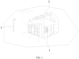
- the energy storage device can convert electrical energy into energy of other forms by physical or chemical means and then to store such energy, and the energy stored in the energy storage device will be released by converting the stored energy into electrical energy if desired. That is, the energy storage device is similar to a large "rechargeable battery". When the light energy and wind energy are sufficient, the electrical energy is stored, and the stored electrical energy is released if desired.
- energy storage devices include as follows.
- the energy storage device 1 may include at least one group of chemical batteries, which utilizes chemical elements within the chemical batteries as an energy storage medium in order to realize charge/discharge through a chemical reaction or change in the energy storage medium. That is, the electric energy generated by light energy and wind energy is stored in the at least one group of chemical batteries through a chemical reaction or change in the energy storage medium. When the usage of external electric energy reaches a peak, the electric energy stored in the at least one group of chemical batteries is released for use through the chemical reaction or change in the energy storage medium, or transferred to places where electric energy is scarce for reuse.
- the energy storage device 1 includes a housing 200, an electrode assembly 600, and an end cover assembly 400.
- the housing 200 includes an accommodation chamber 210 with an opening 201.
- the electrode assembly 600 is accommodated in the accommodation chamber 210.
- the end cover assembly 400 is connected to the housing 200 and closes the opening 201 of the accommodation chamber 210.
- the housing 200 may be a cylindrical structure having the opening 201 at an end of the housing 200.
- the energy storage device 1 includes one end cover assembly 400 that seals the opening 201.
- the housing 200 may also be a cylindrical structure having openings 201 at two ends of the housing 200.
- the energy storage device 1 may include one end cover assembly 400 and one cover plate, or the energy storage device 1 may include two end cover assemblies 400. In this way, the one end cover assembly 400 and the one cover plate, or the two end cover assemblies 400 can seal the two openings 201 of the housing 200, respectively.
- the electrode assembly 600 includes a positive electrode plate, a negative electrode plate, and a separator.
- An operation of the battery cell mainly relies on a movement of metallic ions between the positive electrode plate and the negative electrode plate.
- the positive electrode plate includes a positive current collector and a positive active material layer.
- the positive active material layer is coated on a surface of the positive current collector. Apart of the positive current collector that is not coated with the positive active material layer protrudes from a part of the positive current collector that has been coated with the positive active material layer. The part of the positive current collector that is not coated with the positive active material layer serves as a positive tab.
- the positive current collector may be made of aluminum, and the positive active material may be lithium cobalt oxide, lithium iron phosphate, ternary lithium, lithium manganate, or the like.
- the negative electrode plate includes a negative current collector and a negative active material layer. The negative active material layer is coated on a surface of the negative current collector. A part of the negative current collector that is not coated with the negative active material layer protrudes from a part of the negative current collector that has been coated with the negative active material layer. The part of the negative current collector that is not coated with the negative active material layer serves as a negative tab.
- the negative current collector may be made of copper, and the negative active material may be carbon, silicon, or the like.
- the separator may be made of Polypropylene (PP), Polyethylene (PE), or the like.
- the electrode assembly 600 may have a winding structure or a laminated structure, and the embodiments of the present disclosure are not limited thereto.
- an outer side of the electrode assembly 600 may further be covered with an insulation film (not shown).
- the insulation film is configured to protect a cell from being scratched.
- the insulation film is wrapped around an outer surface of the electrode assembly 600, and a side of the insulation film is connected to the end cover assembly 400 through hot melt bonding for example.
- the end cover assembly 400 includes an end plate 410, a pole 420, a press sheet 440, an upper insulator 460, and a lower insulator 430.
- Each of the pole 420, the press sheet 440, the upper insulator 460, and the lower insulator 430 is mounted at end plate 410.
- the end plate 410 is a glossy aluminum foil.
- the upper insulator 460 and the lower insulator 430 are made of an insulation material, such as plastic.
- the lower insulator 430 and the end plate 410 are stacked together, and the lower insulator 430 is configured to insulate the pole 420 from the end plate 410.
- the upper insulator 460 is wrapped around the pole 420 in a circumferential direction of the pole 420 to insulate the pole 420 from the end plate 410.
- the press sheet 440 is connected to the pole 420, e.g., through welding.
- two poles 420, two press sheets 440, and two upper insulators 460 are provided.
- the two poles 420 are a positive pole and a negative pole, respectively.
- the two press sheets 440 are connected to the two poles 420, respectively.
- the two upper insulators 460 are respectively wrapped around the two poles 420 to insulate each pole 420 from the end plate 410.
- Two sets of poles 420, press sheets 440, and upper insulators 460 are respectively mounted at two ends of the end plate 410 in the length direction (the first direction D1) of the end cover assembly 400.
- the end cover assembly 400 further includes two seals 470.
- the two seals are configured to perform sealing between the two press sheets 440 and the end plate 410 to prevent foreign matters outside the housing 200 from entering the housing 200 through gaps between the poles 420 and the end plate 410.
- the seals 470 are each a sealing ring surrounding the pole 420 in the circumferential direction of the pole 420.
- the end cover assembly 400 further includes an explosion-proof valve 450 connected to the end plate 410.
- the explosion-proof valve 450 is configured to explode and exhaust gas generated in the accommodation chamber 210 of the housing 200 when a gas pressure within the energy storage device 1 reaches a predetermined pressure threshold, preventing the battery from bulging and then exploding, which can further improv the safety of the energy storage device 1.
- the end plate 410 has a first surface 410a and a second surface 410b opposite to each other in the thickness direction (the third direction D3) of the end cover assembly 400.
- the first surface 410a is defined as a surface facing towards the electrode assembly 600
- the second surface 410b is defined as a surface facing away from the electrode assembly 600.
- the end plate 410 further has a mounting hole 411 penetrating the first surface 410a and the second surface 410b.
- the end plate 410 has two mounting holes 411, and the two mounting holes 411 are respectively formed at the two ends of the end plate 410 in the first direction D1.
- the two poles 420 are limited in two mounting holes 411, respectively.
- each of the mounting holes 411 may be in a circular shape, and the present disclosure is not limited in this regard.
- the mounting hole 411 may also be a rectangular, elliptical shape or other shapes.
- the end plate 410 also has an explosion-proof hole 413 penetrating the first surface 410a and the second surface 410b.
- the explosion-proof valve 450 is connected to the end plate 410 and closes the explosion-proof hole 413.
- the explosion-proof hole 413 is located at a middle part of the end plate 410 in the first direction D1 between the two mounting holes 411.
- the explosion-proof hole 413 may be in, but is not limited to, a waist-circle shape.
- the waist-circle shape refers to a closed shape formed by dividing a circle into two semi-circular arcs through a center of the circle and translating the two semi-circular arcs inversely to each other and connecting endpoints of the two semi-circular arcs with two parallel lines of equal lengths.
- the end plate 410 further has an injection hole 414 penetrating the first surface 410a and the second surface 410b.
- An electrolyte may be injected into the accommodation chamber 210 of the housing 200 through the injection hole 414.
- the injection hole 414 may be sealed with a sealing cap (not shown) to prevent leakage of the electrolyte.
- the injection hole 414 is formed between the explosion-proof hole 413 and one of the two mounting holes 411, and is located closer to the explosion-proof hole 413.
- connection relationship among the end plate 410, the pole 420, the press sheet 440, and the lower insulator 430 will be described in detail below with reference to FIG. 6 and FIG. 7 . It should be noted that the connection relationships of the two sets of the poles 420, the press sheets 440 and the lower insulators 430 in the embodiments of the present disclosure are similar, and only one of the two sets will be described as an example.
- the pole 420 includes a pole body 421 and a flange 422.
- the pole body 421 is limited in the mounting hole 411.
- the pole body 421 has a first end 4211 extending beyond the first surface 410a and a second end 4212 extending beyond the second surface 410b.
- the press sheet 440 is connected to an outer peripheral surface of the first end 4211 around the first end 4211 in the circumferential direction of the pole 420.
- the flange 422 is connected to an outer peripheral surface of the second end 4212 around the second end 4212 in the circumferential direction of the pole 420.
- the upper insulator 460 passes through the mounting hole 411 and is wrapped around an outer peripheral surface of the pole body 421 and an outer peripheral surface of the flange 422.
- An orthographic projection of the flange 422 on the second surface 410b in the third direction D3 is located on the second surface 410b, to allow the upper insulator 460 to be partially sandwiched between the flange 422 and the end plate 410.
- the seal 470 surrounds a periphery of the upper insulator 460 and is sandwiched between the press sheet 440 and the end plate 410.
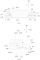
- the lower insulator 430 includes an insulation sheet 431 and a boss 432.
- the insulation sheet 431 has a third surface 431a and a fourth surface 431b opposite to each other in the thickness direction (the third direction D3) of the end cover assembly 400.
- the insulation sheet 431 is attached to the first surface 410a, and the third surface 431a faces towards the first surface 410a.
- the insulation sheet 431 further has a via hole 4311 penetrating the third surface 431a and the fourth surface 431b.
- the pole body 421 passes through the via hole 4311, and the press sheet 440 is limited in the via hole 4311.
- the boss 432 integrally protrudes from the fourth surface 431b and surrounds a periphery of the press sheet 440 in the circumferential direction of the pole 420.
- the boss 432 has a first inclined surface 432a facing away from the press sheet 440 and a top surface 432b facing away from the insulation sheet 431.
- the first inclined surface 432a is connected to the fourth surface 431b and extends obliquely towards an axis of the pole 420 from the fourth surface 431b to the top surface 432b.
- the lower insulator 430 includes the boss 432 protruding from the fourth surface 431b of the insulation sheet 431, and the boss 432 surrounds the periphery of the press sheet 440 in the circumferential direction of the pole 420.
- a thickness of a part of the lower insulator 430 surrounding the periphery of the press sheet 440 is increased, allowing the boss 432 and insulation sheet 431 together to restrict a rotation of the press sheet 440 relative to lower insulator 430 about the axis of the pole 420.
- the first inclined surface 432a of the boss 432 is connected to the fourth surface 431b, and extends obliquely towards the axis of the pole 420 from the fourth surface 431b to the top surface 432b.
- the first inclined surface 432a can provide a counter force opposite to a pressing force exerted by the press sheet 440. Such a pressing force can keep the boss 432 from expanding and deforming to a certain extent. In this way, the boss 432 can continue to prevent the press sheet 440 from rotating.
- an orthographic projection of the press sheet 440 in the third direction D3 on a plane where the first surface 410a is located is in a rounded rectangular shape with one cut-out corner.
- AR angle of the remaining three corners of the rounded rectangular shape is 2 mm, and the present disclosure is not limited in this regard.
- a gap between an outer peripheral surface of the press sheet 440 and a first hole wall surface 4311a of the via hole 4311 may be 0.1 mm, and the present disclosure is not limited in this regard.
- a side surface of boss 432 facing away from the press sheet 440 is an outer annular surface, and the outer annular surface surrounds a periphery of press sheet 440.
- the outer annular surface has a first inclined surface 432a.
- all of the outer annular surface may be the first inclined surface 432a, and may include a flat surface, a curved surface, or a combination thereof.
- a part of the outer annular surface may be the first inclined surface 432a, and may include a flat surface, a curved surface, or a combination thereof.
- the rest of the outer annular surface may be a surface parallel to the axis of the pole 420.
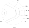
- the boss 432 further has a second inclined surface 432c.
- the second inclined surface 432c is connected to the top surface 432b and extends obliquely towards the axis of the pole 420 from the top surface 432b to the first hole wall surface 4311a of the via hole 4311.
- the boss 432 further has the second inclined surface 432c.
- the second inclined surface 432c is connected to the top surface 432b and extends obliquely towards the axis of the pole 420 from the top surface 432b to the first hole wall surface 4311a of the via hole 4311, to provide a larger distance between the boss 432 and the outer peripheral surface of the press sheet 440.
- a larger gap between the boss 432 and the press sheet 440 can provide a space for an extension of the press sheet 440. Therefore, the press sheet 440 is prevented from being deformed due to the pressing of the lower insulator 430. Further, the lower insulator 430 will not be deformed due to the pressing of the press sheet 440, thereby avoiding influence on the strength due to the deformation of the lower insulator 430.
- a side surface of the boss 432 facing towards the press sheet 440 is an inner annular surface, and the inner annular surface surrounds the periphery of the press sheet 440.
- the inner annular surface has the second inclined surface 432c.
- all of the inner annular surface may be the second inclined surface 432c, and may include a flat surface, a curved surface, or a combination thereof.
- a part of the inner annular surface may be the second inclined surface 432c, and may include a flat surface, a curved surface, or a combination thereof.
- the rest of the inner annular surface may be a surface parallel to the axis of the pole 420.
- the height of the boss 432 does not increase a thickness of the end cover assembly 400 too much, and thus does not occupy a space of the energy storage device 1 in the third direction D3, which is conducive to improving an energy density per unit volume of the energy storage device 1.
- the end plate 410 further has a depression 412 recessed towards the second surface 410b from the first surface 410a, and the mounting hole 411 penetrates a bottom surface of the depression 412.
- the end plate 410 has two depressions 412, and the two mounting holes 411 correspond to the two depressions 412, respectively.
- the press sheet 440 is partially accommodated in the depression 412.
- the end plate 410 has the depression 412, and the press sheet 440 is partially accommodated in the depression 412, allowing the press sheet 440 not to extend beyond the first surface 410a of the end plate 410 too much. Therefore, the thickness of the end cover assembly 400 can be further reduced.
- the lower insulator 430 further includes an insulation protrusion 433 integrally protruding from the third surface 431a.
- the insulation protrusion 433 is accommodated in the depression 412.
- the insulation protrusion 433 is partially arranged between the press sheet 440 and the bottom surface of the depression 412.
- the insulation protrusion 433 of the lower insulator 430 is configured to insulate the press sheet 440 from the end plate 410, and is accommodated in the depression 412. In this way, the thickness of the end cover assembly 400 can be further reduced.
- the insulation protrusion 433 includes a first segment 4331 and a second segment 4332.
- the first segment 4331 extends beyond the third surface 431a in the thickness direction (the third direction D3) of the end cover assembly 400.
- a side surface of the first segment 4331 facing towards the pole 420 is flush with the first hole wall surface 4311a of the via hole 4311.
- the second segment 4332 is connected to the side surface of the first segment 4331 facing towards the pole 420, and is arranged between the press sheet 440 and the bottom surface of the depression 412.
- the first segment 4331 extends beyond the third surface 431a, and the boss 432 protrudes from the fourth surface 431b.
- the first segment 4331, the boss 432, and a part of the insulation sheet 431 close to the press sheet 440 together surround the periphery of the press sheet 440, and they can all stop the press sheet 440 from rotating about the axis of the pole 420.
- An arrangement of the first segment 4331 further increases a thickness of a part of the lower insulator 430 close to the press sheet 440, which further improves the capability of the lower insulator 430 to stop the press sheet 440 from rotating.
- the insulation sheet 431 of the lower insulator 430 has two via holes 4311.
- the two via holes 4311 are used for the two pole bodies 421 of the two poles 420 to pass therethrough, respectively.
- the two press sheets 440 are limited in the two via holes 4311, respectively.
- the insulation sheet 431 further has an aperture 4312 penetrating the third surface 431a and the fourth surface 431b.
- a position of the aperture 4312 corresponds to a position of the injection hole 414 of the end plate 410.
- the electrolyte flows into the housing 200 through the injection hole 414 and the aperture 4312 sequentially.
- the shape of the via hole 4311 is adapted to a shape of the press sheet 440, and the second segment 4332 surrounds a periphery of the pole 420 and the periphery of the upper insulator 460.
- a hole surrounded by the second segment 4332 is in a circular shape, and the present disclosure is not limited in this regard.
- each of two ends of the lower insulator 430 in the length direction (the first direction D1) of the end cover assembly 400 is provided with a protrusion 434.
- the protrusion 434 protrudes from the fourth surface 431b.
- Two side surfaces of the two protrusions 434 opposite to each other in the first direction D1 are flush with two side surfaces of the insulation sheet 431 opposite to each other in the first direction D1, respectively.
- Two end surfaces of the protrusion 434 opposite to each other in the second direction D2 are flush with two side surfaces of the insulation sheet 431 opposite to each other in the second direction D2, respectively. It may be appreciated that a dimension of the protrusion 434 in the second direction D2 is the same as a dimension of the insulation sheet 431 in the second direction D2.
- First recesses 435 are formed in a region of the third surface 431a of the insulation sheet 131 corresponding to the protrusions 434.
- the first recesses 435 are each recessed from the third surface 431a towards the protrusion 434 in the thickness direction (the third direction D3) of the end cover assembly 400.
- Each of the first recesses 435 has two first sidewalls 4351 opposite to each other in the length direction (the first direction D1) of the end cover assembly 400 and two second sidewalls 4352 opposite to each other in the width direction (the second direction D2) of the end cover assembly 400.
- Each first sidewall 4351 has a plurality of first through holes 4351a arranged in the width direction (the second direction D2) of the end cover assembly 400. Each first through hole 4351a penetrates the first sidewall 4351 in the length direction (the first direction D1) of the end cover assembly 400.
- Each second sidewall 4352 has a second through hole 4352a penetrating the second sidewall 4352 in the second direction D2.
- a first bottom wall 4353 of the first recess 435 has a plurality of third through holes 4353a arranged in the second direction D2. Each third through hole 4353a penetrates the first bottom wall 4353 in the third direction D3.
- a plurality of reinforcement plates 436 are arranged in the first recess 435. Each reinforcement plate 436 protrudes from a bottom surface of the first recess 435 and is connected between the two first sidewalls 4351.
- the plurality of reinforcement plates 436 are arranged at intervals in the width direction (the second direction D2) of the end cover assembly 400, and the first recess 435 is divided into a plurality of backflow grooves 437 by the plurality of reinforcement plates 436.
- five reinforcement plates 436 are provided in each first recess 435, and the first recess 435 is divided into six backflow grooves 437 by the five reinforcement plates 436, the present disclosure is not limited in this regard.
- the plurality of backflow grooves 437 are respectively in communication with the plurality of first through holes 4351a at each first sidewall 4351, and are respectively in communication with the plurality of third through holes 4353a. It should be understood that each backflow groove 437 has a third through hole 4353a formed at a bottom of the backflow groove 437, and two sidewalls of each of the backflow grooves 437 opposite to each other in the first direction D1 each has a first through hole 4351a. Further, two of the plurality of backflow grooves 437 located at ends of the plurality of backflow grooves 437 in the second direction D2 are each in communication with one second through hole 4352a.
- the electrolyte in the process of injecting the electrolyte or using the energy storage device 1, the electrolyte easily flows into the plurality of backflow grooves 437 and remains in the backflow grooves 437 without backflow, thereby forming accumulated liquid in the backflow grooves 437, which would affect cycle life of the energy storage device 1.
- each backflow groove 437 is in communication with both the third through hole 4353a and the first through hole 4351a.
- the two backflow grooves 437 located at the ends of the plurality of backflow grooves 437 in the second direction D2 are also in communication with the second through hole 4352a.
- the first through hole 4351a, the second through hole 4352a, and the third through hole 4353a can guide the accumulated liquid remaining in the backflow grooves 437 back to the electrode assembly 600. In this way, the electrolyte can be back flowed and reused. Therefore, the electrolyte can be prevented from remaining in the backflow grooves 437, improving a wettability of the electrode assembly 600 and prolonging the cycle life of the energy storage device 1.
- the first through hole 4351a and the second through hole 4352a may each be in a square shape, a circular shape, or other suitable shapes.
- a side length of the square ranges from 0.1 mm to 5 mm.
- the side length is 0.1 mm, 1 mm, 2 mm, 3 mm, 4 mm, and 5 mm.
- a diameter of the circular shape ranges from 0.1 mm to 5 mm.
- the diameter is 0.1 mm, 1 mm, 2 mm, 3 mm, 4 mm, and 5 mm.
- the first through hole 4351a is formed at a connection between the first sidewall 4351 and the first bottom wall 4353.
- a bottom surface of the first bottom wall 4353 serves as a part of a hole wall of the first through hole 4351a.
- the second through hole 4352a is formed at a connection between the second sidewall 4352 and the first bottom wall 4353.
- the bottom surface of the first bottom wall 4353 serves as a part of a hole wall of the second through hole 4352a.
- the electrolyte remaining in the backflow groove 437 can be more easily flow back to the electrode assembly 600 through at least one of the first through hole 4351a and the second through hole 4352a.
- each reinforcement plate 436 has a fourth through hole 436a.
- the fourth through hole 436a penetrating the reinforcement plate 436 in the width direction (the second direction D2) of the end cover assembly 400.
- an upper surface of the reinforcement plate 436 facing away from the first bottom wall 4353 may be flush with the second surface 410b of the insulation sheet 431.
- the fourth through hole 436a can allow the electrolyte to flow between two adjacent backflow grooves 437.
- the electrolyte in the backflow groove 437 located at one end of the plurality of backflow grooves 437 in the second direction D2 flows into the backflow groove 437 located at another end of the plurality of backflow grooves 437 through the plurality of fourth through holes 436a, and then flows back to the electrode assembly 600 through the second through hole 4352a.
- the fourth through hole 436a may be in a square shape, a circular shape, or other suitable shapes.
- a side length of the square shape ranges from 0.1 mm to 5 mm.
- the side length is 0.1 mm, 1 mm, 2 mm, 3 mm, 4 mm, and 5 mm.
- a diameter of the circle shape ranges from 0.1 mm to 5 mm.
- the diameter is 0.1 mm, 1 mm, 2 mm, 3 mm, 4 mm, or 5 mm.
- the fourth through hole 436a is formed at a connection between the reinforcement plate 436 and the first bottom wall 4353.
- the bottom surface of the first bottom wall 4353 serves as a part of the hole wall of the first through hole 4351a.
- a projection 438 is provided at a position of the lower insulator 430 corresponding to the explosion-proof valve 450.
- the projection 438 protrudes from the fourth surface 431b.
- Two side surfaces of the projection 438 opposite to each other in the second direction D2 are flush with the two side surfaces of the insulation sheet 431 opposite to each other in the second direction D2, respectively. It may be appreciated that a dimension of the projection 438 in the second direction D2 is the same as a width of the insulation sheet 431 in the second direction D2.
- a second recess 439 is formed in a region of the third surface 431a of the insulation sheet 431 corresponding to the projection 438.
- the second recess 439 is recessed towards the projection 438 from the third surface 431a in the thickness direction (the third direction D3) of the end cover assembly 400.
- the second recess 439 has two third sidewalls 4391 opposite to each other in the length direction (the first direction D1) of the end cover assembly 400 and two fourth sidewalls 4392 opposite to each other in the width direction (the second direction D2) of the end cover assembly 400.
- Each third sidewall 4391 has a fifth through hole 4391a.
- the fifth through hole 4391a penetrates the third sidewall 4391 in the length direction (the first direction D1) of the end cover assembly 400.
- Each fourth sidewall 4392 has a sixth through hole 4392a.
- the sixth through hole 4392a penetrates the fourth sidewall 4392 in the width direction (the second direction D2) of the end cover assembly 400.
- the fifth through holes 4391a and the sixth through holes 4392a can guide the accumulated liquid remaining in the second recess 439 back to the electrode assembly 600. In this way, the electrolyte can be returned and reused. Therefore, the electrolyte can be prevented from remaining in the second recess 439, improving the wettability of the electrode assembly 600 and prolonging the cycle life of the energy storage device 1.
- the fifth through hole 4391a is formed at a connection between the third sidewall 4391 and a bottom wall of the second recess 439, and a sixth through hole 4392a is formed at a connection between the fourth sidewall 4392 and the bottom wall of the second recess 439.
- each of the fifth through hole 4391a and the sixth through hole 4392a may be in a square shape, a circular shape, or other suitable shapes.
- a side length of the square ranges from 0.1 mm to 5 mm.
- the side length is 0.1 mm, 1 mm, 2 mm, 3 mm, 4 mm, and 5 mm.
- a diameter of the circular shape ranges from 0.1 mm to 5 mm.
- the diameter is 0.1 mm, 1 mm, 2 mm, 3 mm, 4 mm, and 5 mm.
- the projection 438 includes a middle section 4381 and two side sections 4382.
- the middle section 4371 corresponds to the explosion-proof valve 450.
- the two side sections 4382 are respectively connected to two ends of the middle section 4381 in the width direction (the second direction D2) of the end cover assembly 400.
- a height by which the middle section 4381 protrudes from the fourth surface 431b is smaller than a height by which the side section 4382 protrudes from the fourth surface 431b.
- the height by which the side section 4382 protrudes from the fourth surface 431b is equal to a height by which the protrusion 434 protrudes from the fourth surface 431b.
- the second recess 439 includes a first sub-recess 4393 and two second sub-recesses 4394.
- the first sub-recess 4393 is recessed towards the middle section 4381 from the third surface 431a in the thickness direction (the third direction D3) of the end cover assembly 400.
- the two second sub-recesses 4394 are recessed towards the two side sections 4382 from the third surface 431a in the thickness direction (the third direction D3) of the end cover assembly 400, respectively.
- a depth of the second sub-recess 4394 is greater than a depth of the first sub-recess 4393.
- the seventh through hole 4395 can guide accumulated liquid remaining in the second sub-recess 4394 back to the electrode assembly 600. In this way, the electrolyte can be returned and reused. Therefore, the electrolyte can be prevented from remaining in the second sub-recess 4394, improving the wettability of the electrode assembly and prolonging the cycle life of the energy storage device 1.
- each second sub-recess 4394 has the fifth through hole 4391a formed at two sidewalls of the second sub-recess 4394 opposite to each other in the first direction D1.
- the second bottom wall 4393a of the first sub-recess 4393 further has a perforation 4393b.
- the perforation 4393b penetrates the second bottom wall 4393a of the first sub-recess 4393 in the third direction D3.
- the lower insulator 430 is further provided with a grating structure 480.
- the grating structure 480 is disposed in the perforation 4393b and connected to a hole wall of the perforation 4393b.
- a position of the grating structure 480 corresponds to a position of the explosion-proof valve 450 in the third direction D3.
- the grating structure 480 includes at least one first rib 481, at least one second rib 482, and at least one third rib 483.
- the first rib 481 is linear and extends in the first direction D1. Two ends of the first rib 481 are respectively connected to two opposite hole walls of the perforation 4393b in the first direction D1.
- the second rib 482 is linear and extends in the second direction D2. Two ends of the second rib 482 are respectively connected to two opposite hole walls of the perforation 4393b in the second direction D2.
- the third rib 483 is annular and connected to at least one first rib 481 and at least one second rib 482.
- the perforation 4393b is in a waisted circular shape.
- the two ends of the first rib 481 are respectively connected to two opposite plane hole walls of the perforation 4393b in the first direction D1
- the two ends of the second rib 482 are respectively connected to two opposite arc hole walls of the perforation 4393b in the second direction D2.
- the grating structure 480 includes three first ribs 481, one second rib 482, and three third ribs 483.
- the three first ribs 481 are arranged in parallel in the second direction D2, and the second rib 482 is connected to the three first ribs 481.
- Three third ribs 483 surround a center of the perforation 4393b sequentially and are connected to the three first ribs 481 and the one second rib 482.
- a ring formed by the third ribs 483 is also in a waisted circular shape.
- the fragments of the tab or the blue film can be prevented from floating at a position below the explosion-proof valve 450, which would block a gas passage, thereby causing explosion-proof failure.
- the tab can be prevented from being in direct contact with the explosion-proof valve 450.
- the first rib 481, the second rib 482, and the third rib 483 are cross-connected, which can enhance a structural strength of the grating structure 480.
- each second sub-recess 4394 has a plurality of vent holes 490 formed at the bottom wall of the second sub-recess 4394.
- Each vent hole 490 penetrates the bottom wall of the second sub-recess 4394 in the third direction D3.
- Gas generated inside the energy storage device 1 is accumulated in the second recess 439 through the plurality of vent holes 490 and the grating structure 480. Therefore, a gas pressure reaches a gas pressure explosion threshold of the explosion-proof valve 450, and the explosion-proof valve 450 can be rapidly exploded to quickly release the gas inside the energy storage device 1, thereby improving the safety.
- each backflow groove 437 has a sloped surface 4371 on the bottom of the backflow groove 437.
- the sloped surface 4371 is connected to a side surface of the backflow groove 437 and extends away from the third surface 431a. Further, the sloped surface 4371 is connected to a second hole wall surface 4353b of a third through hole 4353a corresponding to the backflow groove 437.
- each backflow groove 437 has the sloped surface 4371 on the bottom of backflow groove 437.
- the sloped surface 4371 extends away from the third surface 431a from the side surface of the backflow groove 437.
- an end of the sloped surface 4371 connected to the third through hole 4353a is a lowest part of the backflow groove 437.
- the electrolyte can easily flow to the third through hole 4353a along the sloped surface 4371, and then flow back through the third through hole 4353a. Therefore, the electrolyte can be prevented from being adhered to the bottom of the backflow groove 437, which would result in insufficient backflow.
- the third through hole 4353a is formed at a center of the bottom wall of the backflow groove 437.
- the third through hole 4353a is in a circular shape. An axis of the third through hole 4353a is parallel to the third direction D3. In other embodiments, the third through hole 4353a may also be in a rectangular shape, an elliptical shape or the like.
- the sloped surface 4371 may include a planar surface, a curved surface, or a combination thereof.
- the third through hole 4353a is formed at a position on the bottom wall of the backflow groove 437 close to the reinforcement plate 436.
- the third through hole 4353a is located at a middle position on the bottom wall of the backflow groove 437 in the length direction (i.e., the first direction D1) of the end cover assembly 400.
- embodiments of the present disclosure further provide an electric apparatus.
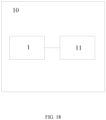
- the electric apparatus includes the energy storage device 1 as described in the above embodiments and a load 11, and the energy storage device 1 is configured to supply power to the electric apparatus.
- the electric apparatus 10 including the energy storage device 1 as described above can improve an operation stability of the electric apparatus, reduce a probability of downtime of the electric apparatus, and improve the use safety of the electric apparatus.
- the load 11 may include, but is not limited to, a household appliance, an industrial equipment, or the like.
- the household appliance may include a rice cooker, a microwave oven, an oven, an induction cooker, or the like.
Landscapes
- Chemical & Material Sciences (AREA)
- Chemical Kinetics & Catalysis (AREA)
- Electrochemistry (AREA)
- General Chemical & Material Sciences (AREA)
- Sealing Battery Cases Or Jackets (AREA)
Applications Claiming Priority (1)
| Application Number | Priority Date | Filing Date | Title |
|---|---|---|---|
| CN202311469778.2A CN117219934B (zh) | 2023-11-07 | 2023-11-07 | 端盖组件、储能装置及用电设备 |
Publications (1)
| Publication Number | Publication Date |
|---|---|
| EP4553961A1 true EP4553961A1 (de) | 2025-05-14 |
Family
ID=89051415
Family Applications (1)
| Application Number | Title | Priority Date | Filing Date |
|---|---|---|---|
| EP24210682.1A Pending EP4553961A1 (de) | 2023-11-07 | 2024-11-04 | Endkappenanordnung, energiespeichervorrichtung und elektrische vorrichtung |
Country Status (4)
| Country | Link |
|---|---|
| US (1) | US20250149763A1 (de) |
| EP (1) | EP4553961A1 (de) |
| CN (1) | CN117219934B (de) |
| WO (1) | WO2025097916A1 (de) |
Families Citing this family (7)
| Publication number | Priority date | Publication date | Assignee | Title |
|---|---|---|---|---|
| CN117219934B (zh) * | 2023-11-07 | 2024-06-28 | 深圳海辰储能科技有限公司 | 端盖组件、储能装置及用电设备 |
| CN117497975B (zh) * | 2023-12-29 | 2024-03-19 | 深圳海辰储能科技有限公司 | 端盖组件、储能装置、用电设备及注液方法 |
| CN117855769B (zh) * | 2024-03-06 | 2024-05-28 | 厦门海辰储能科技股份有限公司 | 下塑胶、端盖组件、储能装置和用电设备 |
| CN118299734B (zh) * | 2024-03-27 | 2025-10-31 | 厦门海辰储能科技股份有限公司 | 端盖组件、储能装置及用电设备 |
| CN222483635U (zh) * | 2024-04-23 | 2025-02-14 | 株式会社Aesc日本 | 盖板组件及包含其的单体电池 |
| CN223124025U (zh) * | 2024-07-10 | 2025-07-18 | 厦门海辰储能科技股份有限公司 | 端盖组件、储能装置及用电设备 |
| CN119786905A (zh) * | 2025-01-02 | 2025-04-08 | 厦门海辰储能科技股份有限公司 | 绝缘件、端盖组件、储能装置及用电设备 |
Citations (4)
| Publication number | Priority date | Publication date | Assignee | Title |
|---|---|---|---|---|
| CN110931667A (zh) * | 2020-01-15 | 2020-03-27 | 苏州炬鸿通讯电脑科技有限公司 | 高容量锂电池盖板 |
| CN216980716U (zh) * | 2021-05-31 | 2022-07-15 | 蜂巢能源科技有限公司 | 电池顶盖结构和电池 |
| WO2023130279A1 (zh) * | 2022-01-05 | 2023-07-13 | 宁德时代新能源科技股份有限公司 | 电池单体及其制造设备和制造方法、电池以及用电装置 |
| CN219801087U (zh) * | 2023-05-09 | 2023-10-03 | 厦门海辰储能科技股份有限公司 | 下塑胶、端盖组件、电池和储能装置 |
Family Cites Families (15)
| Publication number | Priority date | Publication date | Assignee | Title |
|---|---|---|---|---|
| JP5030536B2 (ja) * | 2006-11-06 | 2012-09-19 | 三洋電機株式会社 | 携帯機器の充電台 |
| CN207165624U (zh) * | 2017-07-12 | 2018-03-30 | 湖南艾威尔新能源科技有限公司 | 组合式锂电池正极盖 |
| JP6729637B2 (ja) * | 2018-06-26 | 2020-07-22 | 株式会社Gsユアサ | 蓄電装置 |
| JP7451934B2 (ja) * | 2019-10-23 | 2024-03-19 | 株式会社Gsユアサ | 蓄電設備 |
| WO2022262403A1 (zh) * | 2021-06-16 | 2022-12-22 | 深圳市长盈精密技术股份有限公司 | 动力电池顶盖及其制造方法 |
| CN216389535U (zh) * | 2021-11-08 | 2022-04-26 | 多氟多新能源科技有限公司 | 一种圆柱锂离子电池及其电池模组 |
| CN116365124B (zh) * | 2023-05-31 | 2023-08-11 | 深圳海辰储能控制技术有限公司 | 端盖组件、储能装置和用电设备 |
| CN116487786A (zh) * | 2023-05-31 | 2023-07-25 | 湖北亿纬动力有限公司 | 顶盖组件及电池 |
| CN116864877A (zh) * | 2023-06-29 | 2023-10-10 | 厦门海辰储能科技股份有限公司 | 端盖组件、电池、储能设备及用电系统 |
| CN219959201U (zh) * | 2023-06-30 | 2023-11-03 | 广东省豪鹏新能源科技有限公司 | 一种电池盖板组件及其电池 |
| CN116780061A (zh) * | 2023-06-30 | 2023-09-19 | 广东省豪鹏新能源科技有限公司 | 一种顶盖组件及电池 |
| CN116742229B (zh) * | 2023-08-16 | 2023-12-22 | 深圳海辰储能控制技术有限公司 | 储能装置及用电设备 |
| CN116780065B (zh) * | 2023-08-21 | 2024-01-16 | 深圳海辰储能控制技术有限公司 | 端盖组件、储能装置及用电设备 |
| CN116826261B (zh) * | 2023-08-29 | 2023-12-26 | 深圳海辰储能控制技术有限公司 | 下塑胶、端盖组件、储能装置和用电设备 |
| CN117219934B (zh) * | 2023-11-07 | 2024-06-28 | 深圳海辰储能科技有限公司 | 端盖组件、储能装置及用电设备 |
-
2023
- 2023-11-07 CN CN202311469778.2A patent/CN117219934B/zh active Active
-
2024
- 2024-08-15 WO PCT/CN2024/112253 patent/WO2025097916A1/zh active Pending
- 2024-10-09 US US18/909,994 patent/US20250149763A1/en active Pending
- 2024-11-04 EP EP24210682.1A patent/EP4553961A1/de active Pending
Patent Citations (4)
| Publication number | Priority date | Publication date | Assignee | Title |
|---|---|---|---|---|
| CN110931667A (zh) * | 2020-01-15 | 2020-03-27 | 苏州炬鸿通讯电脑科技有限公司 | 高容量锂电池盖板 |
| CN216980716U (zh) * | 2021-05-31 | 2022-07-15 | 蜂巢能源科技有限公司 | 电池顶盖结构和电池 |
| WO2023130279A1 (zh) * | 2022-01-05 | 2023-07-13 | 宁德时代新能源科技股份有限公司 | 电池单体及其制造设备和制造方法、电池以及用电装置 |
| CN219801087U (zh) * | 2023-05-09 | 2023-10-03 | 厦门海辰储能科技股份有限公司 | 下塑胶、端盖组件、电池和储能装置 |
Also Published As
| Publication number | Publication date |
|---|---|
| CN117219934B (zh) | 2024-06-28 |
| WO2025097916A1 (zh) | 2025-05-15 |
| US20250149763A1 (en) | 2025-05-08 |
| CN117219934A (zh) | 2023-12-12 |
Similar Documents
| Publication | Publication Date | Title |
|---|---|---|
| EP4553961A1 (de) | Endkappenanordnung, energiespeichervorrichtung und elektrische vorrichtung | |
| CN116470240B (zh) | 端盖组件、储能装置以及用电设备 | |
| CN116345029B (zh) | 端盖组件、储能装置以及用电设备 | |
| CN116544627B (zh) | 端盖单元、储能装置及用电设备 | |
| CN116780065B (zh) | 端盖组件、储能装置及用电设备 | |
| CN116780067B (zh) | 储能装置及用电设备 | |
| CN116759760B (zh) | 端盖组件、储能装置及储能系统 | |
| CN120674699A (zh) | 端盖组件、储能装置及用电设备 | |
| WO2024250804A1 (zh) | 储能装置及用电设备 | |
| CN116771964B (zh) | 防爆阀、端盖组件、储能装置以及用电设备 | |
| CN222146495U (zh) | 储能装置壳体、储能装置和用电设备 | |
| US20260018758A1 (en) | End cap assembly, energy storage device and electricity-consumption equipment | |
| CN223911736U (zh) | 端盖组件、储能装置及用电设备 | |
| CN223309003U (zh) | 集流盘、储能装置及用电设备 | |
| CN222980732U (zh) | 储能装置及用电设备 | |
| CN223375191U (zh) | 防爆阀、端盖组件、储能装置及用电设备 | |
| CN222980645U (zh) | 端盖组件、储能装置及用电设备 | |
| CN222775404U (zh) | 端盖组件、储能装置及用电设备 | |
| CN222883679U (zh) | 端盖组件、储能装置及用电设备 | |
| CN222851534U (zh) | 端盖组件、储能装置及用电设备 | |
| CN120073186B (zh) | 储能装置及用电设备 | |
| CN116544346B (zh) | 正极极片、储能装置及用电设备 | |
| CN223218361U (zh) | 储能装置及用电设备 | |
| CN116454492B (zh) | 下塑胶、端盖组件、储能装置及用电设备 | |
| CN223333865U (zh) | 一种电池外壳、储能装置及用电设备 |
Legal Events
| Date | Code | Title | Description |
|---|---|---|---|
| PUAI | Public reference made under article 153(3) epc to a published international application that has entered the european phase |
Free format text: ORIGINAL CODE: 0009012 |
|
| STAA | Information on the status of an ep patent application or granted ep patent |
Free format text: STATUS: THE APPLICATION HAS BEEN PUBLISHED |
|
| AK | Designated contracting states |
Kind code of ref document: A1 Designated state(s): AL AT BE BG CH CY CZ DE DK EE ES FI FR GB GR HR HU IE IS IT LI LT LU LV MC ME MK MT NL NO PL PT RO RS SE SI SK SM TR |
|
| RAP1 | Party data changed (applicant data changed or rights of an application transferred) |
Owner name: HITHIUM TECH HK LIMITED |
|
| STAA | Information on the status of an ep patent application or granted ep patent |
Free format text: STATUS: REQUEST FOR EXAMINATION WAS MADE |
|
| 17P | Request for examination filed |
Effective date: 20250807 |
|
| STAA | Information on the status of an ep patent application or granted ep patent |
Free format text: STATUS: EXAMINATION IS IN PROGRESS |
|
| 17Q | First examination report despatched |
Effective date: 20251008 |