EP4554103A1 - Système de commande - Google Patents
Système de commande Download PDFInfo
- Publication number
- EP4554103A1 EP4554103A1 EP24205168.8A EP24205168A EP4554103A1 EP 4554103 A1 EP4554103 A1 EP 4554103A1 EP 24205168 A EP24205168 A EP 24205168A EP 4554103 A1 EP4554103 A1 EP 4554103A1
- Authority
- EP
- European Patent Office
- Prior art keywords
- detector
- disturbance
- case
- electromagnetic field
- period
- Prior art date
- Legal status (The legal status is an assumption and is not a legal conclusion. Google has not performed a legal analysis and makes no representation as to the accuracy of the status listed.)
- Pending
Links
Images

Classifications
-
- H—ELECTRICITY
- H04—ELECTRIC COMMUNICATION TECHNIQUE
- H04B—TRANSMISSION
- H04B5/00—Near-field transmission systems, e.g. inductive or capacitive transmission systems
- H04B5/70—Near-field transmission systems, e.g. inductive or capacitive transmission systems specially adapted for specific purposes
- H04B5/77—Near-field transmission systems, e.g. inductive or capacitive transmission systems specially adapted for specific purposes for interrogation
-
- B—PERFORMING OPERATIONS; TRANSPORTING
- B60—VEHICLES IN GENERAL
- B60R—VEHICLES, VEHICLE FITTINGS, OR VEHICLE PARTS, NOT OTHERWISE PROVIDED FOR
- B60R25/00—Fittings or systems for preventing or indicating unauthorised use or theft of vehicles
- B60R25/40—Features of the power supply for the anti-theft system, e.g. anti-theft batteries, back-up power supply or means to save battery power
- B60R25/403—Power supply in the vehicle
-
- B—PERFORMING OPERATIONS; TRANSPORTING
- B60—VEHICLES IN GENERAL
- B60R—VEHICLES, VEHICLE FITTINGS, OR VEHICLE PARTS, NOT OTHERWISE PROVIDED FOR
- B60R25/00—Fittings or systems for preventing or indicating unauthorised use or theft of vehicles
- B60R25/01—Fittings or systems for preventing or indicating unauthorised use or theft of vehicles operating on vehicle systems or fittings, e.g. on doors, seats or windscreens
-
- B—PERFORMING OPERATIONS; TRANSPORTING
- B60—VEHICLES IN GENERAL
- B60R—VEHICLES, VEHICLE FITTINGS, OR VEHICLE PARTS, NOT OTHERWISE PROVIDED FOR
- B60R25/00—Fittings or systems for preventing or indicating unauthorised use or theft of vehicles
- B60R25/20—Means to switch the anti-theft system on or off
- B60R25/24—Means to switch the anti-theft system on or off using electronic identifiers containing a code not memorised by the user
-
- B—PERFORMING OPERATIONS; TRANSPORTING
- B60—VEHICLES IN GENERAL
- B60R—VEHICLES, VEHICLE FITTINGS, OR VEHICLE PARTS, NOT OTHERWISE PROVIDED FOR
- B60R25/00—Fittings or systems for preventing or indicating unauthorised use or theft of vehicles
- B60R25/20—Means to switch the anti-theft system on or off
- B60R25/24—Means to switch the anti-theft system on or off using electronic identifiers containing a code not memorised by the user
- B60R25/245—Means to switch the anti-theft system on or off using electronic identifiers containing a code not memorised by the user where the antenna reception area plays a role
-
- G—PHYSICS
- G07—CHECKING-DEVICES
- G07C—TIME OR ATTENDANCE REGISTERS; REGISTERING OR INDICATING THE WORKING OF MACHINES; GENERATING RANDOM NUMBERS; VOTING OR LOTTERY APPARATUS; ARRANGEMENTS, SYSTEMS OR APPARATUS FOR CHECKING NOT PROVIDED FOR ELSEWHERE
- G07C9/00—Individual registration on entry or exit
- G07C9/00174—Electronically operated locks; Circuits therefor; Nonmechanical keys therefor, e.g. passive or active electrical keys or other data carriers without mechanical keys
- G07C9/00309—Electronically operated locks; Circuits therefor; Nonmechanical keys therefor, e.g. passive or active electrical keys or other data carriers without mechanical keys operated with bidirectional data transmission between data carrier and locks
-
- B—PERFORMING OPERATIONS; TRANSPORTING
- B60—VEHICLES IN GENERAL
- B60R—VEHICLES, VEHICLE FITTINGS, OR VEHICLE PARTS, NOT OTHERWISE PROVIDED FOR
- B60R2325/00—Indexing scheme relating to vehicle anti-theft devices
- B60R2325/10—Communication protocols, communication systems of vehicle anti-theft devices
- B60R2325/103—Near field communication [NFC]
-
- G—PHYSICS
- G07—CHECKING-DEVICES
- G07C—TIME OR ATTENDANCE REGISTERS; REGISTERING OR INDICATING THE WORKING OF MACHINES; GENERATING RANDOM NUMBERS; VOTING OR LOTTERY APPARATUS; ARRANGEMENTS, SYSTEMS OR APPARATUS FOR CHECKING NOT PROVIDED FOR ELSEWHERE
- G07C9/00—Individual registration on entry or exit
- G07C9/00174—Electronically operated locks; Circuits therefor; Nonmechanical keys therefor, e.g. passive or active electrical keys or other data carriers without mechanical keys
- G07C2009/00634—Power supply for the lock
-
- G—PHYSICS
- G07—CHECKING-DEVICES
- G07C—TIME OR ATTENDANCE REGISTERS; REGISTERING OR INDICATING THE WORKING OF MACHINES; GENERATING RANDOM NUMBERS; VOTING OR LOTTERY APPARATUS; ARRANGEMENTS, SYSTEMS OR APPARATUS FOR CHECKING NOT PROVIDED FOR ELSEWHERE
- G07C9/00—Individual registration on entry or exit
- G07C9/00174—Electronically operated locks; Circuits therefor; Nonmechanical keys therefor, e.g. passive or active electrical keys or other data carriers without mechanical keys
- G07C2009/00753—Electronically operated locks; Circuits therefor; Nonmechanical keys therefor, e.g. passive or active electrical keys or other data carriers without mechanical keys operated by active electrical keys
- G07C2009/00769—Electronically operated locks; Circuits therefor; Nonmechanical keys therefor, e.g. passive or active electrical keys or other data carriers without mechanical keys operated by active electrical keys with data transmission performed by wireless means
- G07C2009/00793—Electronically operated locks; Circuits therefor; Nonmechanical keys therefor, e.g. passive or active electrical keys or other data carriers without mechanical keys operated by active electrical keys with data transmission performed by wireless means by Hertzian waves
-
- G—PHYSICS
- G07—CHECKING-DEVICES
- G07C—TIME OR ATTENDANCE REGISTERS; REGISTERING OR INDICATING THE WORKING OF MACHINES; GENERATING RANDOM NUMBERS; VOTING OR LOTTERY APPARATUS; ARRANGEMENTS, SYSTEMS OR APPARATUS FOR CHECKING NOT PROVIDED FOR ELSEWHERE
- G07C2209/00—Indexing scheme relating to groups G07C9/00 - G07C9/38
- G07C2209/60—Indexing scheme relating to groups G07C9/00174 - G07C9/00944
- G07C2209/63—Comprising locating means for detecting the position of the data carrier, i.e. within the vehicle or within a certain distance from the vehicle
Definitions
- This disclosure relates to a control system that is mounted on a vehicle and controls communication with a communication device present around the vehicle.
- US 2021/037,0877 A describes a door handle device provided on a door handle of a vehicle.
- the door handle device includes an antenna and near field communication (NFC) reader disposed on a handle portion.
- the antenna generates a magnetic field in surroundings, and the NFC reader detects disturbance of the magnetic field.
- the NFC reader is configured to shift from a power-saving operation state to an active operation state in response to proximity of an NFC tag.
- JP 2016-79600 A describes a vehicle verification system.
- the vehicle verification system includes an on-vehicle device mounted on a vehicle and an electronic key carried by a user of the vehicle. Verification is performed by wireless communication between the on-vehicle device and the electronic key, and if there is an intended operation by a user when the user leaves the vehicle, the verification is stopped for a certain period of time.
- the magnetic field is disturbed also when a metal object different from the NFC tag is brought close due to mischief or the like, and the NFC reader shifts to the active operation state.
- the NFC reader shifts to the active operation state also when the magnetic field is disturbed in an electromagnetic interference (EMI) environment.
- EMI electromagnetic interference
- a characteristic configuration of a control system is a control system that is mounted on a vehicle and controls communication with a communication device present around the vehicle, the control system including a detector that causes an electromagnetic field to be generated around an antenna in a first mode in which the detector operates under a preset first condition, and detects disturbance of the electromagnetic field on the basis of a change in impedance of the antenna, a communicator that outputs information for a communication device associated with the vehicle to surroundings of the vehicle by using near field communication, in a case where the disturbance is detected, and a counter that counts the number of times the information is output, in a case where there is no response to the information even though the communicator outputs the information, in which the detector shifts to a second mode in which the detector operates under a second condition in which power is consumed less than in the first condition, in a case where a result of counting by the counter within a preset first period exceeds a preset number of times.
- the detector detects disturbance of the electromagnetic field, if there is no response to the information within the first period even though the communicator has output the information for the communication device by using the near field communication, the operation of the detector can be shifted to operation in the second mode with reduced power consumption. Therefore, in a case where there is no response to the information within the first period, it is possible to reduce power consumption.
- a simple configuration such as counting by the counter, it is possible to prevent erroneous detection in which a metal object different from the NFC tag approaches due to mischief or the like, in a case where there is no response to the information within the first period.
- a control system is configured to control communication with a communication device present around a vehicle.
- a control system 1 of the present embodiment will be described.
- the control system 1 is not limited to the following embodiments, and various modifications may be made without departing from the gist of the modifications.
- Fig. 1 is a diagram showing a vehicle 2 including the control system 1.
- the control system 1 is provided on a door handle 4 of the vehicle 2.
- the control system 1 of the present embodiment detects a smart key (an example of a "communication device") 3 present around the vehicle 2.
- the smart key 3 is a key associated with the vehicle 2, and can put a lock mechanism of the doors of the vehicle 2 into a locked state or an unlocked state by a lock/unlock switch of the smart key 3 being pressed or a predetermined portion of the door being touched.
- the communication device is a portable terminal such as a smartphone, operation of an application can lock and unlock the door.
- Fig. 2 is a schematic diagram showing a configuration of the control system 1.
- the control system 1 includes an antenna 10, a detector 20, a communicator 30, and a counter 40, and each of the functional units is constructed with hardware, software, or both with a CPU as a core member, in order to perform processing related to communication with the smart key 3.
- Power is fed from a power feeder (not illustrated) to the antenna 10 and generates an electromagnetic field around the antenna 10.
- power is fed to the antenna 10 so that the electromagnetic field is periodically generated around the antenna 10 at a cycle of several hundred milliseconds.
- the antenna 10 is configured to be able to switch an operation state (operation of generating an electromagnetic field) between a first mode and a second mode.
- the first mode is a mode in which the antenna 10 operates under a preset first condition. In the first condition the power to be fed to the antenna 10, a cycle at the electromagnetic field from the antenna 10 is generated, and the like are defined.
- the second mode is a mode in which the antenna 10 operates under a second condition in which power is consumed less than in the first mode.
- Power is consumed less than in the first mode means that power is fed to the antenna 10 with power less than the power defined in the first condition.
- Power less than the power defined in the first condition means that the power to be fed itself may be little, or a power feed cycle may be long. Therefore, in the second condition, power less than the power defined in the first condition or a long power feed cycle is defined. As a matter of course, either the power or the power supply cycle may be defined in the second condition.
- the detector 20 detects disturbance of the electromagnetic field on the basis of a change in impedance of the antenna 10. As described above, an electromagnetic field is periodically generated around the antenna 10. If a metal body including the smart key 3 is present in a region where the electromagnetic field is generated, the electromagnetic field is disturbed. When such an electromagnetic field is disturbed, a change appears in the impedance of the antenna 10. The detector 20 detects disturbance of the electromagnetic field on the basis of such a change in impedance. If the detector 20 detects the disturbance, the detector 20 transmits detection information indicating that the disturbance of the electromagnetic field has been detected, to the communicator 30, which will be described later. The disturbance of the electromagnetic field due to the presence of the metal body is generated even when the smart key 3 runs out of battery, which is convenient.
- the communicator 30 outputs information to surroundings of the vehicle 2 by using near field communication.
- the information is for the smart key 3 and is associated with the vehicle 2.
- the detection information indicating that the disturbance of the electromagnetic field has been detected is transmitted to the communicator 30.
- the smart key 3 associated with the vehicle 2 is a smart key 3 capable of operating the lock mechanism of the doors of the vehicle 2.
- the information is information capable of switching the lock mechanism from either the unlocked or locked state to the other. Specifically, the information corresponds to an electronic lock.
- the communicator 30 outputs the information from the antenna 10 with which disturbance has occurred.
- the near field communication specifically corresponds to near field communication (NFC).
- the smart key 3 acquires the information output by the communicator 30, the smart key 3 makes a response corresponding to the information, and the communicator 30 checks whether or not the smart key 3 is associated with the vehicle 2. If a result of the check indicates that the smart key 3 is associated with the vehicle 2, the communicator 30 continues the communication with the smart key 3. Meanwhile, if the result of the check does not indicate that the smart key 3 is associated with the vehicle 2, the communicator 30 ends the communication with the smart key 3.
- a detection target detected by the detector 20 is disturbance of the electromagnetic field, and the disturbance of the electromagnetic field occurs not only by the presence of the smart key 3 but also by the presence of the metal body.
- the smart key 3 acquires the information from the communicator 30, the smart key 3 responds to the information. Meanwhile, the metal body does not respond even when the information from the communicator 30 reaches the metal body If the smart key 3 is another smart key not associated with the vehicle 2, the smart key 3 cannot respond to the information from the communicator 30 appropriately. Therefore, in a case where there is no response to the information even though the communicator 30 has output the information, the counter 40 counts the number of times the communicator 30 has output the information. The number of times the information has output corresponds to the number of times the communicator 30 has failed the communication. Therefore, the counter 40 counts the number of times the communicator 30 has failed the communication. A result of the counting by the counter 40 is transmitted to the detector 20.
- the number of times the communicator 30 has failed the communication may be counted only when technology detection (TD) in NFC Forum fails, or may be counted when TD and collision resolution (CR) in the NFC Forum fail.
- TD technology detection
- CR collision resolution
- the detector 20 shifts to the second mode in a case where a result of the number counted by the counter 40 in a preset first period exceeds a preset number of times.
- the preset first period can be appropriately changed.
- the first period may be set on the basis of power consumption by the communicator 30 and capacitance of the battery serving as a power source with which the communicator 30 outputs information.
- the first period can be set to, for example, about a few dozen seconds (for example, about 30 seconds).
- the detector 20 shifts to the second mode in which operation is performed under the second condition in which power is consumed less than in the first mode.
- the detector 20 suspends generation of the electromagnetic field for a preset second period.
- the second period may be set to, for example, about several minutes (for example, about five minutes).
- the communicator 30 fails in the communication as described above, if there is a metal body or a smart key not associated with the lock mechanism of the vehicle 2 in a range where the electromagnetic field is generated, the detector 20 continues the detection of the disturbance of the electromagnetic field, and the communicator 30 continues the communication. For this reason, by suspending the generation of the electromagnetic field, it is possible to eliminate a failure of communication and reduce consumption of power required for the communication in a predetermined period.
- the detector 20 measures the disturbance of the electromagnetic field for a preset third period after the second period has elapsed, and, in a case where the disturbance is detected in the third period, determines whether or not there is a response to the information output from the communicator 30, on the basis of the detected disturbance of the electromagnetic field. In a case where there is a response to the information output from the communicator 30, the detector 20 shifts to the operation in the first mode, and when there is no response to the information, the detector 20 continues the operation in the second mode.
- the third period is preferably about as long as the first period described above. As a matter of course, the third period may be longer or shorter than the first period.
- the detector 20 may be configured to measure the disturbance of the electromagnetic field for the third period, and, in a case where the disturbance is detected in the third period, determine whether or not the disturbance continues, on the basis of the detected disturbance. In such a configuration, in a case where the disturbance of the electromagnetic field is not detected, there is no risk of an increase in current consumption due to erroneous detection. Therefore, it is possible to configure the detector 20 to shift to the operation in the first mode in preparation for a user waving a device (smart key herein, card) next time.
- Whether or not the disturbance of the magnetic field caused by a surrounding environment continues may be determined on the basis of antenna drive of the communicator 30. Specifically, if, of a plurality of times an antenna of the communicator 30 is driven, the number of times disturbance is detected does not reach a predetermined number of times, it is determined that the disturbance of the electromagnetic field does not continue. If, of the plurality of times the antenna of the communicator 30 is driven, the number of times disturbance is detected is equal to or greater than the predetermined number of times, it is determined that the disturbance of the electromagnetic field continues. In a case where disturbance of the electromagnetic field is detected during such determination, the operation in the second mode may continue, and the processing may not shift to communication by the communicator 30 (TD or CR in the NFC Forum).
- a configuration in which the detector 20 does not shift to the communication by the communicator 30 when disturbance of the electromagnetic field is detected during such determination is preferable. This is because an effect of power consumption reduction is higher than with a configuration in which the communicator 30 outputs information for the smart key 3 by using the near field communication when disturbance of the electromagnetic field is detected.
- the detector 20 When continuing the operation in the second mode, the detector 20 preferably suspends generation of the electromagnetic field for a period longer than the second period. This makes it possible to further reduce power consumption.
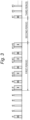
- Fig. 3 is a timing chart in a case where the detector 20 and the communicator 30 are driven on the basis of an NFC standard (hereinafter referred to as "NFC driving").
- NFC driving an NFC standard
- a low-power-consumption card detection function performs transmission at a cycle of 200 milliseconds (#2 to #5). One transmission is only required to take about a few dozen microseconds.
- the "card” in the "low-power-consumption card detection function” includes a smart device and the like, in addition to a card.
- the communicator 30 outputs information with NFC (#7) (denoted by "I” in Fig. 3 ). In a case where there is no response to the output information, it is determined that NFC communication has failed, and the calibration is performed again (#8). When the calibration is completed, the low-power-consumption card detection function performs the transmission again
- the communicator 30 outputs information with NFC (#10).
- NFC NFC
- the NFC driving is performed for the third period. That is, calibration is performed (#17), and transmission is performed (#18, #19).
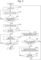
- step #100 calibration is performed (step #100).
- detection by the antenna 10 is started (step #101).
- the low-power-consumption card detection function starts transmission.
- the detection by the antenna 10 continues (#101).
- Step #102: Yes When the detector 20 detects the disturbance of the magnetic field (Step #102: Yes), the communicator 30 outputs information (#103). If there is a response to the output information (step #104: Yes), communication is performed (step #105), and the outputting continues until the communication ends (step #106: Yes).
- step #104 if there is no response to the output information (step #104: No), the counter 40 counts the number of times the information is output (step #107). If a result of counting by the counter 40 in the first period exceeds a preset number of times (predetermined value) (step #108: Yes), the detection by the antenna 10 is suspended for the second period (step #109). In a case where the detection by the antenna 10 is resumed (step #110: Yes), the processing returns to step #100 and continues. In a case where the detection by the antenna 10 is not resumed (step #110: No), the processing returns to step #109 and continues. In step #108, if the result of counting by the counter 40 in the first period is equal to or less than the preset number of times (predetermined value) (step #108: No), the processing returns to step #100 and continues. The processing is performed along the flow described above.
- the detector 20 shifts to the second mode in a case where the result of the number counted by the counter 40 within the preset first period exceeds the preset number of times.
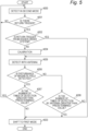
- the detector 20 performs detection in the second mode (step #200)
- if there is a return trigger (step #201: Yes) and the return trigger is from a higher-order system (step #202: Yes) the detector 20 shifts to the first mode (step #203) .
- step #201 in a case where there is no return trigger (step #201: No), the detection in the second mode continues (step #200).
- step #202 in a case where the return trigger is not from the higher-order system (step #202: No), calibration is performed (step #204), and the antenna 10 performs detection (step #205).
- step #206: Yes the detector 20 detects the disturbance of the electromagnetic field
- step #207: Yes the number of times of detection is greater than the predetermined value
- the processing returns to step #200 and continues. Meanwhile, in a case where the number of times of detection is equal to or less than the predetermined value (step #207: No), the detector 20 shifts to the first mode (step #203).
- step #206 in a case where the detector 20 does not detect the disturbance of the electromagnetic field (step #206: No) and the number of times of detection by the antenna 10 is greater than the predetermined value (step #208: Yes), the detector 20 shifts to the first mode (step #203). Meanwhile, in a case where the number of times of detection by the antenna 10 is equal to or less than the predetermined value (step #208: No), the processing returns to step #205 and continues.
- the return trigger in step #201 is, for example, information indicating proximity/contact of a person, from an electrostatic sensor provided a door handle 4.
- the information may be directly transmitted from the electrostatic sensor to a controller (not illustrated) of the control system 1.
- the information may be transmitted from the electrostatic sensor to a controller of the lock mechanism, and the information may be transmitted from the controller of the lock mechanism or another control unit to the controller of the control system 1. Polling may be performed on the controller of the lock mechanism or another control unit.
- the return trigger may be an operation of a lock switch or unlock switch provided with the smart key 3. When the lock mechanism is operated by using a digital key, a lock command or an unlock command by using the digital key can be used.
- the electrostatic sensor provided on a door handle 4 detects proximity/contact of a person (for example, in a case where the user grips an unlock sensor), the user can naturally resume a function during the operation of getting into the vehicle (that is, the low-power-consumption card detection function can be automatically resumed). Therefore, convenience can be improved.
- the communicator 30 performs TD in communication based on NFC. However, in a case where there is no response to the TD, processing may be performed treating it as an erroneous detection. In a case where it is a response to this TD, CR may be performed. Then, if a type of the card is a specific type (for example, "T4AT”), the processing may continue, and if the type of the card is not the specific type (for example, "T2T”), processing may be performed treating it as an erroneous detection.
- a type of the card is a specific type (for example, "T4AT")
- T2T specific type
- the detector 20 suspends the generation of the electromagnetic field for the preset second period.
- the detector 20 may extend the cycle of the generating the electromagnetic field for the preset second period.
- a threshold value for detecting disturbance of the electromagnetic field may be changed. In this case also, power consumption can be reduced.
- the detector 20 detects disturbance of the electromagnetic field for the third period after a lapse of the second period.
- the detector 20 shifts to the operation in the first mode if, on the basis of the disturbance of the electromagnetic field detected in the third period, there is a response to the information output from the communicator 30, whereas continues the operation in the second mode if there is no response to the information.
- the detector 20 may be configured to detect the disturbance of the electromagnetic field for the third period after the lapse of the second period and shift to the operation in the first mode regardless of, on the basis of the disturbance of the electromagnetic field detected in the third period, whether or not there is a response to the information output from the communicator 30.
- the detector 20 suspends the generation of the electromagnetic field for a period longer than the second period when continuing the operation in the second mode.
- the detector 20 may be configured to extend the cycle of generating an electromagnetic field for a period longer than the second period, when continuing the operation in the second mode.
- the communication device is the smart key 3
- the communication device may be a card key or a portable terminal such as a smartphone.
- Technology according to this disclosure can be used for a control system that is mounted on a vehicle and controls communication with a communication device present around the vehicle.
Landscapes
- Engineering & Computer Science (AREA)
- Mechanical Engineering (AREA)
- Computer Networks & Wireless Communication (AREA)
- Physics & Mathematics (AREA)
- General Physics & Mathematics (AREA)
- Signal Processing (AREA)
- Lock And Its Accessories (AREA)
Applications Claiming Priority (1)
| Application Number | Priority Date | Filing Date | Title |
|---|---|---|---|
| JP2023193069A JP2025080068A (ja) | 2023-11-13 | 2023-11-13 | 制御システム |
Publications (1)
| Publication Number | Publication Date |
|---|---|
| EP4554103A1 true EP4554103A1 (fr) | 2025-05-14 |
Family
ID=93037288
Family Applications (1)
| Application Number | Title | Priority Date | Filing Date |
|---|---|---|---|
| EP24205168.8A Pending EP4554103A1 (fr) | 2023-11-13 | 2024-10-08 | Système de commande |
Country Status (4)
| Country | Link |
|---|---|
| US (1) | US20250153683A1 (fr) |
| EP (1) | EP4554103A1 (fr) |
| JP (1) | JP2025080068A (fr) |
| CN (1) | CN119997161A (fr) |
Citations (3)
| Publication number | Priority date | Publication date | Assignee | Title |
|---|---|---|---|---|
| US20150365990A1 (en) * | 2014-06-13 | 2015-12-17 | Canon Kabushiki Kaisha | Communication apparatus, control method, and storage medium |
| JP2016079600A (ja) | 2014-10-14 | 2016-05-16 | 矢崎総業株式会社 | 車両用認証システム |
| US20210370877A1 (en) | 2020-05-28 | 2021-12-02 | Magna Mirrors Of America, Inc. | Vehicular access system using nfc reader in door handle |
-
2023
- 2023-11-13 JP JP2023193069A patent/JP2025080068A/ja active Pending
-
2024
- 2024-10-08 EP EP24205168.8A patent/EP4554103A1/fr active Pending
- 2024-10-09 US US18/910,510 patent/US20250153683A1/en active Pending
- 2024-11-08 CN CN202411590765.5A patent/CN119997161A/zh active Pending
Patent Citations (3)
| Publication number | Priority date | Publication date | Assignee | Title |
|---|---|---|---|---|
| US20150365990A1 (en) * | 2014-06-13 | 2015-12-17 | Canon Kabushiki Kaisha | Communication apparatus, control method, and storage medium |
| JP2016079600A (ja) | 2014-10-14 | 2016-05-16 | 矢崎総業株式会社 | 車両用認証システム |
| US20210370877A1 (en) | 2020-05-28 | 2021-12-02 | Magna Mirrors Of America, Inc. | Vehicular access system using nfc reader in door handle |
Also Published As
| Publication number | Publication date |
|---|---|
| US20250153683A1 (en) | 2025-05-15 |
| CN119997161A (zh) | 2025-05-13 |
| JP2025080068A (ja) | 2025-05-23 |
Similar Documents
| Publication | Publication Date | Title |
|---|---|---|
| EP2612795B1 (fr) | Circuit de communication sans fil | |
| KR101972623B1 (ko) | 무선 키 포브 및 상호작용 시스템을 위한 신호 구분 | |
| US6269449B1 (en) | Capacitive wake-up mechanism for hand held data entry unit | |
| EP2866215A1 (fr) | Terminal à écran tactile et son procédé d'alarme | |
| US20110018680A1 (en) | Security system with power saving feature and method thereof | |
| CN108973933B (zh) | 控制系统、车载设备及电子钥匙 | |
| US10911953B2 (en) | In-vehicle authentication device and portable device authentication method | |
| KR20190081118A (ko) | 차량 제어 장치 및 방법 | |
| CN107422913A (zh) | 电子设备及其触摸屏控制方法 | |
| EP4554103A1 (fr) | Système de commande | |
| EP1542888B1 (fr) | Systeme antidemarrage de vehicule a moteur avec alarme de cle de contact et detection de l'etat d'allumage | |
| KR100966526B1 (ko) | 비접촉식 도어록 시스템 및 그의 제어방법 | |
| US10609161B2 (en) | System and method for controlling operation of IoT device | |
| WO2014176874A1 (fr) | Procédé et dispositif pour un réveil automatique d'extrémité d'émission de système d'émission de puissance électrique sans fil à partir d'un état de veille | |
| CN118093034B (zh) | 一种计算机睡眠模式的唤醒方法和装置 | |
| US11059456B2 (en) | In-vehicle authentication device and portable device authentication method | |
| CN116321056B (zh) | 一种车载nfc控制方法、控制系统、车载nfc模块和汽车 | |
| KR20150006560A (ko) | 디지털 도어 락의 소비 전력 감소를 통한 배터리 수명 연장 방법 및 이를 이용한 디지털 도어락 시스템 | |
| CN116129564A (zh) | 防误触发的智能锁具 | |
| US10864890B2 (en) | Electronic key and method for operating an electronic key | |
| JP7347996B2 (ja) | 異常検出装置及び電子キー | |
| CN120225403A (zh) | 用于控制车辆功能的遥控钥匙 | |
| CN114578451A (zh) | 人体感应检测方法及装置 | |
| US20240391419A1 (en) | Wireless vehicle control device | |
| JP2024103309A (ja) | 車両用通信装置 |
Legal Events
| Date | Code | Title | Description |
|---|---|---|---|
| PUAI | Public reference made under article 153(3) epc to a published international application that has entered the european phase |
Free format text: ORIGINAL CODE: 0009012 |
|
| STAA | Information on the status of an ep patent application or granted ep patent |
Free format text: STATUS: THE APPLICATION HAS BEEN PUBLISHED |
|
| AK | Designated contracting states |
Kind code of ref document: A1 Designated state(s): AL AT BE BG CH CY CZ DE DK EE ES FI FR GB GR HR HU IE IS IT LI LT LU LV MC ME MK MT NL NO PL PT RO RS SE SI SK SM TR |
|
| STAA | Information on the status of an ep patent application or granted ep patent |
Free format text: STATUS: REQUEST FOR EXAMINATION WAS MADE |
|
| 17P | Request for examination filed |
Effective date: 20250829 |