EP4554324A1 - Gestion optimisée de ressources radio à l'aide d'approches d'apprentissage automatique dans des réseaux o-ran - Google Patents
Gestion optimisée de ressources radio à l'aide d'approches d'apprentissage automatique dans des réseaux o-ran Download PDFInfo
- Publication number
- EP4554324A1 EP4554324A1 EP24211511.1A EP24211511A EP4554324A1 EP 4554324 A1 EP4554324 A1 EP 4554324A1 EP 24211511 A EP24211511 A EP 24211511A EP 4554324 A1 EP4554324 A1 EP 4554324A1
- Authority
- EP
- European Patent Office
- Prior art keywords
- sqi
- level
- rrm
- per
- state
- Prior art date
- Legal status (The legal status is an assumption and is not a legal conclusion. Google has not performed a legal analysis and makes no representation as to the accuracy of the status listed.)
- Pending
Links
Images









Classifications
-
- H—ELECTRICITY
- H04—ELECTRIC COMMUNICATION TECHNIQUE
- H04W—WIRELESS COMMUNICATION NETWORKS
- H04W88/00—Devices specially adapted for wireless communication networks, e.g. terminals, base stations or access point devices
- H04W88/08—Access point devices
- H04W88/085—Access point devices with remote components
-
- H—ELECTRICITY
- H04—ELECTRIC COMMUNICATION TECHNIQUE
- H04W—WIRELESS COMMUNICATION NETWORKS
- H04W72/00—Local resource management
- H04W72/50—Allocation or scheduling criteria for wireless resources
- H04W72/52—Allocation or scheduling criteria for wireless resources based on load
-
- H—ELECTRICITY
- H04—ELECTRIC COMMUNICATION TECHNIQUE
- H04W—WIRELESS COMMUNICATION NETWORKS
- H04W72/00—Local resource management
- H04W72/50—Allocation or scheduling criteria for wireless resources
- H04W72/54—Allocation or scheduling criteria for wireless resources based on quality criteria
- H04W72/542—Allocation or scheduling criteria for wireless resources based on quality criteria using measured or perceived quality
Definitions
- the present disclosure is related to 5G wireless networks, and relates more particularly to optimized radio resource management using machine learning approaches in O-RAN networks.
- 5GNR Next Generation Radio Access Network
- gNodeB monolithic gNB
- PHY physical
- MAC Medium Access Control
- RLC Radio Link Control
- PDCP Packet Data Convergence Protocol
- SDAP Service Data Adaptation Protocol
- the Protocol Data Unit (PDU) layer 9010 corresponds to the PDU carried between the user equipment (UE) 101 and the data network (DN) 9011 over the PDU session.
- PDU Protocol Data Unit
- UE 101 is connected to the 5G access network (AN) 902, which AN 902 is in turn connected via the N3 interface to the Intermediate UPF (I-UPF) 903a portion of the UPF 903, which I-UPF 903a is in turn connected via the N9 interface to the PDU session anchor 903b portion of the UPF 903, and which PDU session anchor 903b is connected to the DN 9011.
- the PDU session can correspond to Internet Protocol version 4 (IPv4), IPv6, or both types of IP packets (IPv4v6).
- IPv4 Internet Protocol version 4
- IPv6 IPv6
- GTP-U General Packet Radio Services Tunneling Protocol - User Plane
- RRC Radio Resource Control
- PDCP Packet Control
- RLC Packet Control
- MAC Packet Control
- PHY Packet Control sublayer
- NAS Non-Access Stratum
- NG-Radio Access Network (NG-RAN) architecture from 3GPP TS 38.401 is shown in FIGS. 4-5 .
- the NG-RAN consists of a set of gNBs connected to the 5GC through the NG interface.
- the NG-RAN 301 consists of a set of gNBs 302 connected to the 5GC 303 through the NG interface.
- Each gNB comprises gNB-CU 304 and one or more gNB-DU 305 (see FIG. 4 ).
- FIG. 4 NG-Radio Access Network
- E1 is the interface between gNB-CU-CP (CU-Control Plane) 304a and gNB-CU-UP (CU-User Plane) 304b
- F1-C is the interface between gNB-CU-CP 304a and gNB-DU 305
- F1-U is the interface between gNB-CU-UP 304b and gNB-DU 305.
- gNB 302 can consist of a gNB-CU-CP 304a, multiple gNB-CU-UPs (or gNB-CU-UP instances) 304b and multiple gNB-DUs (or gNB-DU instances) 305.
- One gNB-DU 305 is connected to only one gNB-CU-CP 304a, and one gNB-CU-UP 304b is connected to only one gNB-CU-CP 304a.
- the purpose of the NOTIFY procedure is to enable the gNB-DU to inform the gNB-CU that the QoS of an already established GBR DRB cannot be fulfilled any longer or that it can be fulfilled again.
- the procedure uses UE-associated signaling.
- the gNB-DU 305 initiates the procedure by sending a NOTIFY 601 message to the gNB-CU 304.
- the NOTIFY message shall contain the list of the GBR DRBs associated with notification control for which the QoS is not fulfilled anymore or for which the QoS is fulfilled again by the gNB-DU.
- the gNB-DU may also indicate an alternative QoS parameters set which it can currently fulfil in the Current QoS Parameters Set Index IE.
- the gNB-CU may identify which are the affected PDU sessions and QoS flows.
- the gNB-CU may inform the 5GC that the QoS for these PDU sessions or QoS flows is not fulfilled any longer or it is fulfilled again.
- the Alternative QoS Parameters Set Notify Index IE indicates the QoS parameters set which can be currently fulfilled.
- the Alternative QoS Parameters Set Index IE contains alternative sets of QoS parameters which the gNB can indicate to be fulfilled when notification control is enabled and the gNB cannot fulfill the requested list of QoS parameters.
- L2 of 5G NR is split into the following sublayers (in accordance with 3GPP TS 38.300):
- FIG. 10 is a block diagram illustrating DL L2 structure (including a scheduler or priority handling module which handles multiple UEs in a cell), in accordance with 3GPP TS 38.300.
- FIG. 11 is a block diagram illustrating L2 structure for a single UE, in accordance with 3GPP TS 38.300.
- FIG. 12 is a block diagram illustrating L2 data flow example, in accordance with 3GPP TS 38.300 (in FIG. 12 , H denotes headers or sub-headers).
- Open Radio Access Network is based on disaggregated components which are connected through open and standardized interfaces based on 3GPP NG-RAN.
- An overview of O-RAN with disaggregated RAN CU (Centralized Unit), DU (Distributed Unit), and RU (Radio Unit), near-real-time Radio Intelligent Controller (Near-RT-RIC) and non-real-time RIC is illustrated in FIG. 13 .
- the CU (shown split as O-CU-CP 801a and O-CU-UP 801b) and the DU (shown as O-DU 802) are connected using the F1 interface (with F1-C for control plane and F1-U for user plane traffic) over a mid-haul (MH) path.
- One DU can host multiple cells (e.g., one DU could host 24 cells) and each cell may support many users. For example, one cell may support 800 Radio Resource Control (RRC)-connected users and out of these 800, there may be 250 Active users (i.e., users that have data to send at a given point of time).
- RRC Radio Resource Control
- a cell site can comprise multiple sectors, and each sector can support multiple cells.
- one site could comprise three sectors and each sector could support eight cells (with eight cells in each sector on different frequency bands).
- One CU-CP (CU-Control Plane) could support multiple DUs and thus multiple cells.
- a CU-CP could support 1,000 cells and around 100,000 User Equipments (UEs).
- Each UE could support multiple Data Radio Bearers (DRB) and there could be multiple instances of CU-UP (CU-User Plane) to serve these DRBs.
- DRB Data Radio Bearers
- CU-UP CU-User Plane
- each UE could support 4 DRBs, and 400,000 DRBs (corresponding to 100,000 UEs) may be served by five CU-UP instances (and one CU-CP instance).
- the DU could be located in a private data center, or it could be located at a cell-site.
- the CU could also be in a private data center or even hosted on a public cloud system.
- the DU and CU which are typically located at different physical locations, could be tens of kilometers apart.
- the CU communicates with a 5G core system, which could also be hosted in the same public cloud system (or could be hosted by a different cloud provider).
- a RU (Radio Unit) (shown as O-RU 803 in FIG. 13 ) is located at a cell-site and communicates with the DU via a front-haul (FH) interface.
- FH front-haul
- the E2 nodes (CU and DU) are connected to the near-real-time RIC 132 using the E2 interface.
- the E2 interface is used to send data (e.g., user and/or cell KPMs) from the RAN, and deploy control actions and policies to the RAN at near-real-time RIC 132.
- the applications or services at the near-real-time RIC 132 that deploys the control actions and policies to the RAN are called xApps.
- the E2 node advertises the metrics it can expose, and an xApp in the near-RT RIC can send a subscription message specifying key performance metrics which are of interest.
- the near-real-time RIC 132 is connected to the non-real-time RIC 133 (which is shown as part of Service Management and Orchestration (SMO) Framework 805 in FIG. 13 ) using the A1 interface.
- the applications that are hosted at non-RT-RIC are called rApps.
- O-eNB 806 which is shown as being connected to the near-real-time RIC 132 and the SMO Framework 805
- O-Cloud 804 which is shown as being connected to the SMO Framework 805).
- PDU connectivity service is a service that provides exchange of PDUs between a UE and a data network identified by a Data Network Name (DNN).
- DNN Data Network Name
- the PDU Connecitivity service is supported via PDU sessions that are established upon request from the UE.
- the DNN defines the interface to a specific external data network.
- One or more QoS flows can be supported in a PDU session. All the packets belonging to a specific QoS flow have the same 5QI (5G QoS Identifier).
- a PDU session consists of the following: Data Radio Bearer which is between UE and CU in RAN; and an NG-U GTP tunnel which is between CU-UP and UPF (User Plane Function) in the core network.
- FIG. 14 illustrates an example PDU session (in accordance with 3GPP TS 23.501) consisting of multiple DRBs, where each DRB can consist of multiple QoS flows.
- PDU session 901 UE 101; access network (AN) 902; and UPF 903, which includes Packet Detection Rules (PDRs) 9031.
- PDRs Packet Detection Rules
- FIG. 15 in the context of multiple PDU sessions involving multiple DRBs and QoS Flow Identifiers (QFIs), which PDU sessions are implemented involving UE 101, gNodeB 102, UPF 903, and DNNs 9011a and 9011b
- FIG. 16 in the context of Radio Resource Management (RRM) (for connecting UE 101 to the network via RU 306) with a MAC Scheduler 1001):
- RRM Radio Resource Management
- FIG. 15 illustrates multiple PDU sessions involving multiple DRBs and QoS Flow Identifiers (QFIs).
- the first column represents the SQI value.
- the second column lists the different resource types, i.e., as one of Non-GBR, GBR, Delay-critical GBR.
- the third column (“Default Priority Level") represents the priority level Priority5QI, for which the lower the value the higher the priority of the corresponding QoS flow.
- the fourth column represents the Packet Delay Budget (PDB), which defines an upper bound for the time that a packet may be delayed between the UE and the N6 termination point at the UPF.
- the fifth column represents the Packet Error Rate (PER).
- the sixth column represents the maximimum data burst volume for delay-critical GBR types.
- the seventh column represents averaging window for GBR, delay critical GBR types.
- SQI value 1 represents GBR resource type with the default priority value of 20, PDB of 100 ms, PER of 0.01, and averaging window of 2000ms. Conversational voice falls under this catogery.
- SQI value 7 represents non-GBR resource type with the default priority value of 70, PDB of 100ms and PER of 0.001. Voice, video (live streaming), and interactive gaming fall under this catogery.
- Electricity distribution - medium voltage, Process automation monitoring 4 50 300 ms (NOTE 11, NOTE 13) 10 -6 N/A 2000 ms Non-Conversational Video (Buffered Streaming) 65 (NOTE 9, NOTE 12) 7 75 ms (NOTE 7, NOTE 8) 10 -2 N/A 2000 ms Mission Critical user plane Push To Talk voice (e.g., MCPTT) 66 (NOTE 12) 20 100 ms (NOTE 10, NOTE 13) 10 -2 N/A 2000 ms Non-Mission-Critical user plane Push To Talk voice 67 (NOTE 12) 15 100 ms (NOTE 10, NOTE 13) 10 -3 N/A 2000 ms Mission Critical Video user plane 75 (NOTE 14) 71 56 150 ms (NOTE 11, NOTE 13, NOTE 15) 10 -6 N/A 2000 ms "Live" Uplink Streaming (e.g.
- Non-GBR 10 100 ms NOTE 10, NOTE 13) 10 -6 N/A N/A IMS Signalling 6 60 300 ms (NOTE 10, NOTE 13) 10 -6 N/A N/A Video (Buffered Streaming) TCP-based (e.g., www, e-mail, chat, ftp, p2p file sharing, progressive video, etc.) 7 70 100 ms (NOTE 10, NOTE 13) 10 -3 N/A N/A Voice, Video (Live Streaming) Interactive Gaming
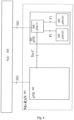
- FIG. 16 is a block diagram illustrating RRM with a MAC Scheduler.
- L2 methods (such as MAC scheduler) play a critical role in allocating radio resources to different UEs in a cellular network.
- Reinforcement Learning is a feedback-based machine learning technique in which an agent learns to behave in an environment by performing actions and seeing the results of the actions. For each good action, the agent gets a positive feedback, and for each bad action, the agent gets a negative feedback or penalty.
- reinforcement learning the agent learns automatically using feedbacks, without the use of any labelled data. Since there is no labelled data, the agent is bound to learn by its experience only. The primary goal of an agent in reinforcement learning is to improve the performance by getting the maximum overall reward (or minimum overall cost).
- MDP Markov Decision Process
- RL reinforcement learning
- MDP is used to formalize the reinforcement learning (RL) problems. If the environment is completely observable, then its dynamics can be modelled as a Markov Process.
- MDP which is illustrated in FIG. 17 , the agent 1701 constantly interacts with the environment 1702 and performs actions; at each action, the environment responds and generates a new state.
- MDP is used to describe the environment for the RL, and almost all the RL problems can be formalized using MDP.
- MDP contains a tuple of four elements, as follows: States, Actions, Costs/Rewards, and Transition Probabilities. Provided below is a simple set notation to represent each of the elements in an MDP:
- a finite MDP is when there are finite states, finite costs, and finite actions. Only the finite MDP is considered in RL.
- MDP uses Markov property, i.e., the current state transition does not depend on any past action or state. Hence, MDP is an RL problem that satisfies the Markov property.
- Markov Process is a memoryless process with a sequence of random states that uses the Markov Property. Markov process is also known as Markov chain, which is a tuple (S, P) on state S and transition probability matrix P. These two components (S and P) can define the dynamics of the system.
- Reinforcement learning uses MDPs where the probabilities or costs are unknown. Reinforcement learning can solve MDPs without explicit specification of the transition probabilities; the values of the transition probabilities are needed in value and policy iteration. Reinforcement learning can also be combined with function approximation to address problems with a very large number of states.
- example approaches include: Value-based approach (Value iteration methods); Q-learning; Deep Q Neural Network (DQN); and Policy-based approach (Policy iteration methods).
- V(s) indicates an example value-based approach.
- Q-learning which is discussed later and is a variant of the value-based approach, takes one additional parameter as a current action 'a'.
- Q-learning involves learning the value function Q (s, a), which characterizes how good it is to take an action "a" at a particular state "s".
- the main objective of Q-learning is to learn the policy which can inform the agent what actions should be taken for minimizing the overall cost.
- the goal of the agent in Q-learning is to optimize the value of Q.
- the value of Q-learning can be derived from the Bellman equation.
- Q represents the quality of the action at each state, so instead of using a value at each state, we will use a pair of state and action, i.e., Q(s, a).
- Q-value specifies which action is more beneficial or lucrative than others, and according to the best Q-value, the agent takes his next move.
- the Bellman equation can be used for deriving the Q-value.
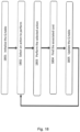
- the flowchart shown in FIG. 18 illustrates the workings of Q-learning.
- the Q-table is initialized.
- an action to perform is selected.
- the selected action is performed.
- the associated cost for the action is found.
- the Q-table is updated.
- Deep Q Neural Network is a Q-learning using Neural networks.
- DQN Deep Q Neural Network
- neural network instead of defining a Q-table, neural network approximates the Q-values for each action and state.
- Policy-based approach is to find the optimal policy for the minimum future costs without using the value function. It converges for finite state, action set. It has two steps, policy evaluation and policy improvement. In policy improvement, If the policy is same at two consecutive epochs, then it is the optimal policy.
- the policy-based approach involves mainly two types of policies: 1) Deterministic policy, whereby the same action is produced by the policy for any given state; and 2) Stochastic policy, whereby for each state there is a distribution over set of actions possible at that state.
- 3GPP TR 37.817 focuses on the analysis of data needed at the Model Training function and Model Inference function from Data Collection. Where AI/ML functionality resides within the current RAN architecture depends on the deployment and the specific use cases.
- the Model Training and Model Inference functions should be able to request, if needed, specific information to be used to train or execute the AI/MI, algorithm and to avoid reception of unnecessary information. The nature of such information depends on the use case and on the AI/ML algorithm.
- the Model Inference function should signal the outputs of the model only to nodes that have explicitly requested them (e.g., via subscription), or nodes that take actions based on the output from Model Inference.
- NG-RAN stand-alone SA
- EN-DC and MR-DC are less prioritized, but not precluded from 3GPP Release 18.
- RRM Radio Resource Management
- the RRM analytics module can be hosted at one of the following components, for example: 1) RIC (e.g., Near-RT RIC) server; 2) gNodeB (e.g., at CU-UP or CU-CP); 3) 5G Network Data Analytics Function (NWDAF) server; or 4) Operations, Administration Maintenance (OAM) server.
- RIC e.g., Near-RT RIC
- gNodeB e.g., at CU-UP or CU-CP
- NWDAF 5G Network Data Analytics Function
- OAM Operations, Administration Maintenance
- These performance measurements include the following for each UE: Buffer Occupancy (BO) at SQI level; Channel State Information (CSI); UE Throughput; Packet delay at SQI level; Packet error rate (PER) at SQI level; and PF metric. These performance measurements are analyzed at the RRM analytics module for each UE.
- BO Buffer Occupancy
- CSI Channel State Information
- PER Packet error rate
- the RRM analytics module is located at Near-RT RIC.
- the following steps are implemented:
- the RRM analytics module is located at the CU-UP.
- the following steps are implemented:
- the mapping of the RRM-related decision making process to a reinforcement learning problem by formalizing it using an MDP which involves four elements: States; Actions; Costs/Rewards; and Transition Probabilities.
- the cost can be written as a function of costs associated with each state variable, as shown below in the expanded cost equation.
- the overall cost is a weighted sum of the costs associated with the BO, GBR, PDB, PER, and PF state variables and cell level cost.
- C CL ( s (t), a (t)) represents the cell level cost associated with all the active UEs in the cell.
- the vector notation s (t), a (t) represents the set of states and actions of all the active UEs.
- c i s t , a t w 1 * c BO i s t , a t + w 2 * c PDB i s t , a t + w 3 * c GBR i s t , a t + w 4 * c PER i s t , a t + w 5 * c PF i s t , a t + w 6 * C CL s ⁇ t , a ⁇ t
- a method for optimizing RRM methods includes a Value iteration policy (Policy 1).
- Policy 1 Value iteration policy
- s, a) 1.
- s, a) P(s"
- s, a) 0.5.
- s, a) P(s"
- s, a) 0.5.
- system and/or network components e.g., RRM analytics module, RIC, and RAN nodes (including CU-CP, CU-UP, and DU) can be implemented as i) software executed on processor(s) and/or servers, and/or ii) dedicated hardware modules comprising processor(s) executing software, to implement the respective functionalities of the system and/or network components.
- network includes both networks and internetworks of all kinds, including the Internet, and is not limited to any particular type of network or inter-network.
- first and second are used to distinguish one element, set, data, object or thing from another, and are not used to designate relative position or arrangement in time.
- Coupled means a relationship between or among two or more devices, apparatus, files, programs, applications, media, components, networks, systems, subsystems, and/or means, constituting any one or more of (a) a connection, whether direct or through one or more other devices, apparatus, files, programs, applications, media, components, networks, systems, subsystems, or means, (b) a communications relationship, whether direct or through one or more other devices, apparatus, files, programs, applications, media, components, networks, systems, subsystems, or means, and/or (c) a functional relationship in which the operation of any one or more devices, apparatus, files, programs, applications, media, components, networks, systems, subsystems, or means depends, in whole or in part, on the operation of any one or more others thereof.
- the RRM analytics module can be hosted at one of the following components, for example: 1) RIC (e.g., Near-RT RIC) server; 2) gNodeB (e.g., at CU-UP or CU-CP); 3) 5G Network Data Analytics Function (NWDAF) server; or 4) Operations, Administration Maintenance (OAM) server.
- RIC e.g., Near-RT RIC
- gNodeB e.g., at CU-UP or CU-CP
- NWDAF 5G Network Data Analytics Function
- OAM Operations, Administration Maintenance
- These performance measurements include the following for each UE: Buffer Occupancy (BO) at SQI level; Channel State Information (CSI); UE Throughput; Packet delay at SQI level; Packet error rate (PER) at SQI level; and PF metric. These performance measurements are analyzed at the RRM analytics module for each UE.
- BO Buffer Occupancy
- CSI Channel State Information
- PER Packet error rate
- the RRM analytics module forms an MDP. Forming an MDP requires states, actions, transition probabilities and costs. Each performance measurement takes a certain range of values. We quantize (or classify) the range of values taken by each performance measurement to n levels, where n is a finite value. Here, we consider each performance measurement as a state variable of an MDP. There are finite state variables, and each state variable takes finite values, so the state space is finite.
- the DU and RRM analytics module e.g., hosted at CU-UP, CU-CP, or Near-RT RIC
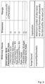
- RRM Parameters Set List as shown in Table 2 below.
- the RRM Parameters Set List IE contains the sets of performance measurements gNB-DU can indicate to the RRM Analytics module. We index the entries in the table using Performance Measurement Index, shown in Table 1 below, for easy communication across different interfaces.
- the Performance Measurement Index IE indicates the index of the items within the RRM Parameter Set List corresponding to the current state of the UE after taking an action.
- the actions at each state for any UE are binary, i.e., ⁇ schedule (1), not schedule (0) ⁇ .
- the DU wants to communicate its current performance measurements to RRM analytics module, first the DU chooses one entry from the RRM Parameters Set List based on the state it landed upon (current state after the action) based on the action.
- transition probabilities are unknown, the transition probabilities are obtained during the training phase and can be used at later stage, as explained below in the section discussing RRM related decisions using reinforcement learning (as part of Method 2).
- ⁇ Indicates the index of the items within the RRM Parameters Set List IE corresponding to the currently state of the active UE after taking and action.
- POLICY IE is implemented as a lookup table with (state, action) pair, i.e., for each state assigning a near-optimal action to achieve optimal allocation of radio resources.
- the lookup table i.e., POLICY
- a Binary Action Array (which is a bit string of zeroes and ones) is included as part of the POLICY (as shown in Table 3 below) and sent with size equal to the length of Performance Measurement Index to represent the near optimal action for each state.
- This Binary Action Array will be used at the DU for scheduling until the next policy is received from the RRM analytics module. This will reduce the computational burden at the DU for allocating radio resources, since no computation at the DU is required for resource allocation. It is a lightweight approach from the DU point of view.
- Method 1A (Machine Learning based RRM analytics module at near-RT-RIC):
- first variant the RRM analytics module is located at Near-RT RIC.
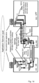
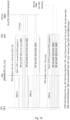
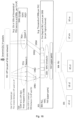
- the following steps are implemented (as shown in FIG. 20 , which illustrates the Near-RT RIC subscribing to various performance measurements from the DU for each UE, and as shown in FIG. 21 , which illustrates the overall RRM analytics at the Near-RT RIC):
- the Near-RT RIC sends the policy (i.e., lookup table) based on RIC event trigger (e.g., specified periodicity), as shown by the process arrow 2104 in FIG. 21 .
- DU node detects the RIC event trigger and modifies the ongoing process according to the policy, as shown by the block 2105 in FIG. 21 .
- the DU runs this policy until a new policy is received at the DU.
- Method 1B Reinforcement learning based RRM analytics module at CU-UP:
- second variant of the first example system and method is presented, in which second variant the RRM analytics module is located at the CU-UP.
- the following steps are implemented (as shown in FIGS. 20-26 , with FIG. 26 illustrating the overall RRM analytics steps (I) -(V) described below):
- Method 2 RRM-related decisions using reinforcement learning: In this section, we describe the mapping of the RRM-related decision making process to a reinforcement learning problem by formalizing it using an MDP.
- MDP involves four elements: States; Actions; Costs/Rewards; and Transition Probabilities. These elements are represented as follows:
- the state S i is represented using the following variables: Buffer Occupancy (BO) at 5QI level; UE Channel State Information (CSI); UE Throughput; Packet delay at SQI level; Packet error rate (PER) at SQI level; and PF metric for that UE.
- Normalized Buffer Occupancy (BO normalized): We consider normalized BO for DRBs of different SQIs. For a particular SQI DRB of the UE i , the normalized BO is BO for the particular SQI DRB of the UE i divided by the average packet size for that SQI in the cell. At the UE level, the normalized BO is a summation over all the normalized BOs of different SQI traffics carried by the UE.
- the BO_normalized for UE i which is represented as BO_normalizedi, is equal to (V 1 /A 1 )+ (V 2 /A 2 ).
- the range of values taken by BO_normalized for all the UEs is quantized to n 1 levels (for example 4 levels).
- BO_normalized is in the range of [0, B]
- CSI UE Channel State Information
- the time and frequency resources that can be used by the UE to report CSI are controlled by the gNB.
- CSI can consist of Channel Quality Indicator (CQI), precoding matrix indicator (PMI), CSI-RS resource indicator (CRI), SS/PBCH Block Resource indicator (SSBRI), layer indicator (LI), rank indicator (RI), L1-RSRP or L1-SINR.
- CQI shall be calculated conditioned on the reported PMI, RI, and CRI.
- CQI reporting may be periodic or aperiodic.
- CQI index ranges from 0 to 15 in the 3GPP table, and higher the CQI index better the channel quality.
- Delay observed by packets of a DRB in DU We consider packet delay budget from the SQI table and estimate a target delay for packets of each DRB in the DU. For example, with PDB of 300 ms for SQI 9 (video streaming) DRB, we could have a target delay in DU for this DRB as 230 ms in a deployment scenario. We refer to this target delay as target DU PDB (e.g., target DU PDB is equal to 230 ms in this example).
- target DU PDB e.g., target DU PDB is equal to 230 ms in this example.
- We quantize the delay experienced by packets of a DRB into n 2 different levels. We give an example for three levels here (i.e., n 2 3).
- SQI e.g., VoNR
- the observed PER is between Z 1 % and Z 2 % of the target PER (e.g., for VoNR, if Z 1 is equal to 50% and Z 2 is equal to 100%, the observed PER is between 1 ⁇ 2*10 -2 to 10 -2 ), it is classified as level 2 (e.g., "good”). If the observed PER is between Z 2 % and Z 3 % of the target PER (e.g., for VoNR, if Z 2 is equal to 100% and Z 3 is equal to 150%, the observed PER is between 10 -2 to 1.5*10 -2 ), it is classified as level 3 (e.g., "average”).
- the observed PER is above Z 3 % of the target PER (e.g., for VoNR, if Z 3 is equal to 150%, the observed PER is more than 1.5*10 -2 ), it is classified as level 4 (e.g., "poor"). If there are multiple SQI flows per a given UE, then we consider the worst-case PER of the SQI as the UE level PER and classify it as one of the multiple levels described above.
- the transition probability matrix is of finite size and it's cardinality
- b*2.
- the actions at each UE state are two implies 2 K possibilities for K UEs in the cell. So, the transition probability matrix is of size (n 1 *n 2 *n 3 *n 4 *n 5 *n 6 *2) K .
- Table 4 below provides an illustrative example to show the dimensions of the lookup table.
- Normalized _BO can be ⁇ 0,1 ⁇
- CQI (of CSI) can be ⁇ 3, 10 ⁇
- packet delay can be ⁇ Good, Bad ⁇
- throughput can be ⁇ Good, Bad ⁇
- packet error rate can be ⁇ Good, Bad ⁇
- PF metric can be ⁇ Low, High ⁇ .
- the state space can be represented as shown in the Table 4 Errore. L'rare riferimento non è stata trovata. with the 64 possible states.
- the cost can be written as a function of costs associated with each state variable as shown below.
- the overall cost is a weighted sum of the costs associated with the BO, GBR, PDB, PER, and PF state variables and cell level cost.
- C CL ( s (t), a (t)) represents the cell level cost associated with all the active UEs in the cell.
- the vector notation s (t), a (t) represents the set of states and actions of all the active UEs.
- C' (s(t), a(t)) as individual UE level costs of each of the state variable, and summing them over all the active UEs in the cell will result in the cell level cost as required in the above equation.
- the optimal action is not to schedule, and the associated cost is always zero as long as they stay inactive.
- the BO immediate cost The BO immediate cost for a UE when the action is equal to zero (i.e., this UE is not scheduled) is BO_normalized i .
- the BO immediate cost when the action is equal to one is sum of c i BO and min ⁇ 0, BO_normalized i - Sched_data_normalized i ⁇ , where c i BO is the cost for scheduling UE i with its BO and Sched_data_normalizedi is summation over normalized scheduled data per SQI level (similar to that of BO_normalized i ).
- normalized scheduled data is summation over all the normalized scheduled data of different SQI traffics carried by the UE.
- the normalized scheduled data for UE i which is represented as Sched_data_normalizedi is equal to (U 1 /A 1 )+ (U 2 /A 2 ).
- the PDB immediate cost The PDB immediate cost for a UE i when the action is equal to zero is the maximum of zero and the difference of the RLC queuing delay (Qdelay RLC,i ) and the PDB.
- the PDB immediate cost is simply the cost for taking action equal to one, which is c i PDB .
- the GBR immediate cost The GBR immediate cost for a UE when the action is equal to zero is the remaining data.
- the GBR immediate cost when the action is equal to one is the sum of c i GBR and the difference of remaining data (remData) and scheduled data (schedData).
- pkts_unsuccessful_t is the number of packets not successfully delivered in time-slot t
- pkts_transmitted_t is the number of packets transmitted in time-slot t.
- the PF immediate cost is the difference of PF max and the ratio of r i (t) to the R avg,i (t - 1).
- the PF immediate cost for a UE when the action is equal to one is the difference of c i PF + PF max and the ratio r i t ⁇ ⁇ R avg , i t ⁇ 1 + 1 ⁇ ⁇ ⁇ b i t .
- C' (s(t), a(t)) is the sum of weighted cost functions of the state variables BO, PDB, GBR, PER, and PF, and the cell level cost, as shown below.
- C s ⁇ t , a ⁇ t w 1 * C BO s ⁇ t , a ⁇ t + w 2 * C GBR s ⁇ t , a ⁇ t + w 3 * C PDB s ⁇ t , a ⁇ t + w 4 * C PER s ⁇ t , a ⁇ t + w 5 * C PF s ⁇ t , a ⁇ t + w 6 * C CL s ⁇ t , a ⁇ t
- Discounted cost essentially determines how much the reinforcement learning agents care about costs in the distant future relative to those in the immediate future. Normally, discount factor ranges from 0 to 1, i.e., ⁇ ⁇ [0,1).
- transition probabilities based on the different states it landed upon and the number of times landed upon on each state. For example, for state 's', taking action "a" 100 times resulted in landing upon states s' , s" , s′′′ for 20, 30, and 50 times, respectively, then the updated transition probabilities are given as follows: F( s'
- s , a ) 0.2, P( s"
- s , a ) 0.3, P( s′′′
- Policy 2 After the initial learning of transition probabilities as mentioned in Policy 1, we run the reinforcement learning method with exploration and exploitation strategy.
- the exploration stage we choose the action from the set of all possible actions uniformly at random. For example, in a given time slot, if there are four active UEs, then there are sixteen possible combinations of actions, i.e., ⁇ 0000,0001...,1111 ⁇ . If the policy chooses exploration, then it chooses any one of the actions from the 16 possible actions with 1/16 probability.
- Policy 2 chooses the action that gave the minimum cost till now (during the training phase).
- the policy chooses the action corresponding to the minimum cost, which is 10, i.e., the policy chooses action 0000.
- exploitation is chosen with probability (1 minus delta) and exploration is chosen with probability delta .
- delta is a parameter controlling the amount of exploration vs. exploitation.
- This "delta" parameter could be a fixed parameter or it can be adjusted either according to a schedule (e.g., making the agent explore progressively less), or adaptively based on some policies.
- the policy is used to create a candidate list of UEs which can be scheduled (for a given state) in a given slot.
- a subset of UEs is picked up from this candidate list and allocated resources based on some policies which could consider QoS requirements (such as delay, throughput, etc.), buffer depth (of pending packets at the base station for the corresponding logical channel), and other parameters for each UE.
- candidate UEs to serve in a slot are selected as per Policy 1 or Policy 2 above.
- a given base station system can serve only a certain number of UEs in slot (e.g., max Z UEs in a slot). If the number of selected candidate UEs is higher than what the base station can serve in that slot (i.e., Z in this example), the radio resource management (RRM) module selects Z UEs using various policies (e.g., selecting Z UEs which have packets that may miss their delay targets if not scheduled, or selecting Z UEs which may miss their throughput and delay targets if not scheduled).
- RRM radio resource management
- These selected UEs are allocated resources (e.g., PRBs) based on another set of policies (e.g., drain full buffer for each selected UE, or serve a subset of packets queued for each UE and give opportunity to more of the Z UEs to be served in that slot) as long as PRBs are available in that slot.
- resources e.g., PRBs
- another set of policies e.g., drain full buffer for each selected UE, or serve a subset of packets queued for each UE and give opportunity to more of the Z UEs to be served in that slot
Landscapes
- Engineering & Computer Science (AREA)
- Computer Networks & Wireless Communication (AREA)
- Signal Processing (AREA)
- Mobile Radio Communication Systems (AREA)
Applications Claiming Priority (2)
| Application Number | Priority Date | Filing Date | Title |
|---|---|---|---|
| IN202321076223 | 2023-11-08 | ||
| US18/936,587 US20250150897A1 (en) | 2023-11-08 | 2024-11-04 | Optimized radio resource management using machine learning approaches in o-ran networks |
Publications (1)
| Publication Number | Publication Date |
|---|---|
| EP4554324A1 true EP4554324A1 (fr) | 2025-05-14 |
Family
ID=93455921
Family Applications (1)
| Application Number | Title | Priority Date | Filing Date |
|---|---|---|---|
| EP24211511.1A Pending EP4554324A1 (fr) | 2023-11-08 | 2024-11-07 | Gestion optimisée de ressources radio à l'aide d'approches d'apprentissage automatique dans des réseaux o-ran |
Country Status (1)
| Country | Link |
|---|---|
| EP (1) | EP4554324A1 (fr) |
Cited By (1)
| Publication number | Priority date | Publication date | Assignee | Title |
|---|---|---|---|---|
| EP4598102A1 (fr) * | 2024-01-31 | 2025-08-06 | Mavenir Systems, Inc. | Politiques de gestion de ressources radio assistée par apprentissage automatique (rrm) pour un débit de données élevé à faible latence et autres applications dans des réseaux o-ran |
Citations (4)
| Publication number | Priority date | Publication date | Assignee | Title |
|---|---|---|---|---|
| US20210258866A1 (en) * | 2020-05-05 | 2021-08-19 | Intel Corporation | Resource allocation and activation/deactivation configuration of open radio access network (o-ran) network slice subnets |
| US20210377804A1 (en) * | 2020-06-02 | 2021-12-02 | At&T Intellectual Property I, L.P. | Network traffic splitting for dual connectivity user equipment |
| WO2023091664A1 (fr) * | 2021-11-19 | 2023-05-25 | Intel Corporation | Gestionnaire d'applications intelligent de réseau d'accès radio |
| WO2023153898A1 (fr) * | 2022-02-14 | 2023-08-17 | 삼성전자주식회사 | Dispositif électronique de gestion de ressources matérielles, et procédé de fonctionnement associé |
-
2024
- 2024-11-07 EP EP24211511.1A patent/EP4554324A1/fr active Pending
Patent Citations (4)
| Publication number | Priority date | Publication date | Assignee | Title |
|---|---|---|---|---|
| US20210258866A1 (en) * | 2020-05-05 | 2021-08-19 | Intel Corporation | Resource allocation and activation/deactivation configuration of open radio access network (o-ran) network slice subnets |
| US20210377804A1 (en) * | 2020-06-02 | 2021-12-02 | At&T Intellectual Property I, L.P. | Network traffic splitting for dual connectivity user equipment |
| WO2023091664A1 (fr) * | 2021-11-19 | 2023-05-25 | Intel Corporation | Gestionnaire d'applications intelligent de réseau d'accès radio |
| WO2023153898A1 (fr) * | 2022-02-14 | 2023-08-17 | 삼성전자주식회사 | Dispositif électronique de gestion de ressources matérielles, et procédé de fonctionnement associé |
Non-Patent Citations (1)
| Title |
|---|
| O-RAN WORKING GROUP 2: "O-RAN Working Group 2. Non-RT RIC & A1 Interface: Use Cases and Requirements. O-RAN.WG2.Use-Case-Requirements-v06.00", 1 June 2022 (2022-06-01), XP009555958, Retrieved from the Internet <URL:https://specifications.o-ran.org/specifications> * |
Cited By (1)
| Publication number | Priority date | Publication date | Assignee | Title |
|---|---|---|---|---|
| EP4598102A1 (fr) * | 2024-01-31 | 2025-08-06 | Mavenir Systems, Inc. | Politiques de gestion de ressources radio assistée par apprentissage automatique (rrm) pour un débit de données élevé à faible latence et autres applications dans des réseaux o-ran |
Similar Documents
| Publication | Publication Date | Title |
|---|---|---|
| EP3198836B1 (fr) | Système et procédé de gestion de transmission dans des réseaux définis par logiciel | |
| EP2830380B1 (fr) | Planification de transmission de liaison montante des porteurs de débit binaire non-garanti basé sur l'indicateur de classe de qualité | |
| US9071984B1 (en) | Modifying a data flow mechanism variable in a communication network | |
| US20250063388A1 (en) | Policy-based performance management for 5g network slices in o-ran networks | |
| US20250088464A1 (en) | System and methods for network slicing for coexistence of low latency, low loss and scalable throughput (l4s) and non-l4s traffic in wireless networks | |
| Dighriri et al. | Big data environment for smart healthcare applications over 5g mobile network | |
| EP4554324A1 (fr) | Gestion optimisée de ressources radio à l'aide d'approches d'apprentissage automatique dans des réseaux o-ran | |
| US20240314628A1 (en) | Optimizations for overload control in o-ran networks | |
| EP4598102A1 (fr) | Politiques de gestion de ressources radio assistée par apprentissage automatique (rrm) pour un débit de données élevé à faible latence et autres applications dans des réseaux o-ran | |
| US20230090081A1 (en) | Method and Apparatus for Processing New Service | |
| EP4510520A1 (fr) | Gestion de performance basée sur une politique pour tranches de réseau 5g dans des réseaux o-ran | |
| US20250063451A1 (en) | Load balancing optimizations for o-ran networks | |
| US20250063387A1 (en) | Optimized radio resource management for 5g network slicing | |
| CN102612060B (zh) | 一种基于熵值计算的跨层设计兼容性的评判方法 | |
| EP4432725A1 (fr) | Optimisations pour la régulation de surcharge dans des réseaux o-ran | |
| US20250150897A1 (en) | Optimized radio resource management using machine learning approaches in o-ran networks | |
| EP4648463A1 (fr) | Optimisation de gestion de ressources radio dans des réseaux o-ran à l'aide de techniques d'apprentissage automatique | |
| EP4418718B1 (fr) | Gestion de performance basée sur une politique pour réseaux o-ran hautement extensibles | |
| Wang et al. | Video telephony over downlink LTE systems with/without QoS provisioning | |
| EP4507372B1 (fr) | Optimisations de commande de flux de cu-du pour une interface intermédiaire avec perte dans des réseaux o-ran | |
| US20250365749A1 (en) | Optimizing radio resource management in o-ran networks using machine learning techniques | |
| US20240284441A1 (en) | Policy based performance management for highly scalable o-ran networks | |
| EP4513956A1 (fr) | Optimisations d'équilibrage de charge pour réseaux o-ran | |
| US20250055795A1 (en) | Cu-du flow control optimizations for lossy midhaul in o-ran networks | |
| CN114727308B (zh) | 一种信息处理方法、装置、设备及可读存储介质 |
Legal Events
| Date | Code | Title | Description |
|---|---|---|---|
| PUAI | Public reference made under article 153(3) epc to a published international application that has entered the european phase |
Free format text: ORIGINAL CODE: 0009012 |
|
| STAA | Information on the status of an ep patent application or granted ep patent |
Free format text: STATUS: REQUEST FOR EXAMINATION WAS MADE |
|
| 17P | Request for examination filed |
Effective date: 20241107 |
|
| AK | Designated contracting states |
Kind code of ref document: A1 Designated state(s): AL AT BE BG CH CY CZ DE DK EE ES FI FR GB GR HR HU IE IS IT LI LT LU LV MC ME MK MT NL NO PL PT RO RS SE SI SK SM TR |