EP4555852A1 - Einzugswalzenantrieb für dreschwerk einer landwirtschaftlichen erntemaschine - Google Patents
Einzugswalzenantrieb für dreschwerk einer landwirtschaftlichen erntemaschine Download PDFInfo
- Publication number
- EP4555852A1 EP4555852A1 EP24213026.8A EP24213026A EP4555852A1 EP 4555852 A1 EP4555852 A1 EP 4555852A1 EP 24213026 A EP24213026 A EP 24213026A EP 4555852 A1 EP4555852 A1 EP 4555852A1
- Authority
- EP
- European Patent Office
- Prior art keywords
- threshing
- feed roll
- rotor
- threshing rotor
- grain
- Prior art date
- Legal status (The legal status is an assumption and is not a legal conclusion. Google has not performed a legal analysis and makes no representation as to the accuracy of the status listed.)
- Pending
Links
Images

Classifications
-
- A—HUMAN NECESSITIES
- A01—AGRICULTURE; FORESTRY; ANIMAL HUSBANDRY; HUNTING; TRAPPING; FISHING
- A01F—PROCESSING OF HARVESTED PRODUCE; HAY OR STRAW PRESSES; DEVICES FOR STORING AGRICULTURAL OR HORTICULTURAL PRODUCE
- A01F12/00—Parts or details of threshing apparatus
- A01F12/10—Feeders
-
- A—HUMAN NECESSITIES
- A01—AGRICULTURE; FORESTRY; ANIMAL HUSBANDRY; HUNTING; TRAPPING; FISHING
- A01D—HARVESTING; MOWING
- A01D69/00—Driving mechanisms or parts thereof for harvesters or mowers
- A01D69/06—Gearings
-
- A—HUMAN NECESSITIES
- A01—AGRICULTURE; FORESTRY; ANIMAL HUSBANDRY; HUNTING; TRAPPING; FISHING
- A01F—PROCESSING OF HARVESTED PRODUCE; HAY OR STRAW PRESSES; DEVICES FOR STORING AGRICULTURAL OR HORTICULTURAL PRODUCE
- A01F12/00—Parts or details of threshing apparatus
- A01F12/10—Feeders
- A01F12/12—Feeders without band-cutters
-
- A—HUMAN NECESSITIES
- A01—AGRICULTURE; FORESTRY; ANIMAL HUSBANDRY; HUNTING; TRAPPING; FISHING
- A01F—PROCESSING OF HARVESTED PRODUCE; HAY OR STRAW PRESSES; DEVICES FOR STORING AGRICULTURAL OR HORTICULTURAL PRODUCE
- A01F12/00—Parts or details of threshing apparatus
- A01F12/56—Driving mechanisms for the threshing parts
-
- A—HUMAN NECESSITIES
- A01—AGRICULTURE; FORESTRY; ANIMAL HUSBANDRY; HUNTING; TRAPPING; FISHING
- A01F—PROCESSING OF HARVESTED PRODUCE; HAY OR STRAW PRESSES; DEVICES FOR STORING AGRICULTURAL OR HORTICULTURAL PRODUCE
- A01F7/00—Threshing apparatus
- A01F7/02—Threshing apparatus with rotating tools
- A01F7/06—Threshing apparatus with rotating tools with axles in line with the feeding direction ; Axial threshing machines
Definitions
- the present invention relates to agricultural harvesters such as combines, and, more particularly, to feed rolls incorporated in the harvester crop processing section.
- a combine An agricultural harvester known as a "combine” is historically termed such because it combines multiple harvesting functions with a single harvesting unit, such as picking, threshing, separating and cleaning.
- a combine includes a header which removes the crop from a field, and a feeder housing which transports the crop matter into a threshing rotor.
- the threshing rotor rotates within a perforated housing, which may be in the form of adjustable concaves, and performs a threshing operation on the crop to remove the grain.
- Once the grain is threshed it falls through perforations in the concaves and is transported to a grain pan. From the grain pan the grain is cleaned using a cleaning system, and is then transported to a grain tank onboard the combine.
- the cleaning system includes a cleaning fan which blows air through oscillating sieves to discharge chaff and other debris toward the rear of the combine.
- Non-grain crop material such as straw
- Non-grain crop material, such as straw, from the threshing section proceeds through a straw chopper and out the rear of the combine.
- the combine When the grain tank becomes full, the combine is positioned adjacent a vehicle into which the grain is to be unloaded, such as a semi-trailer, gravity box, straight truck, or the like; and an unloading system on the combine is actuated to transfer the grain into the vehicle.
- a rotary threshing or separating system includes one or more rotors which can extend axially (front to rear) or transversely within the body of the combine, and which are partially or fully surrounded by a perforated concave.
- the crop material is threshed and separated by the rotation of the rotor within the concave.
- Coarser non-grain crop material such as stalks and leaves are transported to the rear of the combine and discharged back to the field.
- the separated grain, together with some finer non-grain crop material such as chaff, dust, straw, and other crop residue are discharged through the concaves and fall onto the grain pan where they are transported to the cleaning system.
- the grain and finer non-grain crop material may also fall directly onto the cleaning system itself.
- the cleaning system further separates the grain from non-grain crop material, and typically includes a fan directing an air flow stream upwardly and rearwardly through vertically arranged sieves which oscillate in a fore and aft manner.
- the air flow stream lifts and carries the lighter non-grain crop material towards the rear end of the combine for discharge to the field.
- Grain and non-grain crop material remaining on the upper and lower sieves are physically separated by the reciprocating action of the sieves as the material moves rearwardly. Any grain and/or non-grain crop material remaining on the top surface of the upper sieve or sieve assembly are discharged at the rear of the combine. Grain falling through the lower sieve lands on a bottom pan of the cleaning system, where it is conveyed forwardly toward a clean grain auger.
- the clean grain auger is positioned below the lower sieve, and receives clean grain from each sieve and from the bottom pan of the cleaning system.
- the clean grain auger then augers the clean grain laterally sideways to a clean grain elevator, which in turn conveys the clean grain to a grain tank onboard the combine.
- a dynamic feed roll is positioned between a conveyor from the header and the threshing rotor so as to provide an arrangement where rocks that may be have been swept up in the harvesting process are dropped below to a container for removal without passing through the threshing rotor and the remainder of the processing apparatus.
- the dynamic feed roll has a series of projections that propel the harvested crop below the roll and through a chute into the inlet end of the threshing rotor. The projections also knock out rocks or other hard objects from the crop stream. There is a gap between the conveying apparatus and the chute for the dynamic feed roll through which the rocks may drop.
- the threshing rotor may be driven at one of a selected rotational speed by a gear box or drive train connected to the agricultural harvester power unit.
- the drive for the dynamic feed roll which also is driven from the power unit, must have some type of variable speed drive train. Such a requirement requires a balance between complexity and cost of the system and the need to synchronize the dynamic feed roll with the processing requirement of the threshing rotor.
- the present invention seeks to simplify the synchronizing of the rotational rate between the dynamic feed roll and the threshing rotor of an agricultural harvester.
- the invention in one form, is a threshing apparatus including a conveyor for transferring harvested crop in a given direction. At least one threshing rotor receives harvested crop and is driven for rotation about an axis parallel to the direction of the harvested crop for separating grain material. A dynamic feed roll is interposed between the conveyor and the threshing rotor and is rotatable about an axis at a right angle to the axis of rotation of the threshing rotor to control the feed of harvested crop from the conveyor to the threshing rotor.
- a drive train is connected to and driven by the threshing rotor and includes a right angle drive connected to the at least one threshing rotor and provides a shaft parallel to the axis of rotation of the dynamic feed roll extending to one end thereof and a mechanical connection between the shaft the dynamic feed roll so that the dynamic feed roll is driven in synchronism with the rotation of the threshing rotor.
- An advantage of the present invention is a robust synchronism between the dynamic feed roll and the threshing rotor but in a direct and effective way.
- Another advantage is the elimination of a separate gear box for the dynamic feed roll and still achieve synchronism.
- Another advantage is the improved feeding of crop to the threshing rotor.
- Another advantage is the improved removal of rocks from the crop stream.
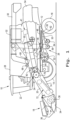
- FIG. 1 there is shown an agricultural harvester in the form of a combine 10, which generally includes a chassis 12, ground engaging wheels 14 and 16, header 18, feeder housing 20, operator cab 22, threshing and separating system 24, cleaning system 26, grain tank 28, and unloading auger 30.
- Front wheels 14 are larger flotation type wheels, and rear wheels 16 are smaller steerable wheels. Motive force is selectively applied to front wheels 14 through a power unit in the form of a diesel engine 32 and a transmission (not shown).
- a power unit in the form of a diesel engine 32 and a transmission (not shown).
- combine 10 is shown as including wheels, is also to be understood that combine 10 may include tracks, such as full tracks or half tracks.
- Header 18 is mounted to the front of combine 10 and includes a cutter bar 34 for severing crops from a field during forward motion of combine 10.
- a rotatable reel 36 feeds the crop into header 18, and a double auger 38 feeds the severed crop laterally inwardly from each side toward feeder housing 20.
- Feeder housing 20 conveys the cut crop to threshing and separating system 24, and is selectively vertically movable using appropriate actuators, such as hydraulic cylinders (not shown).
- Threshing and separating system 24 is of the axial-flow type, and generally includes a rotor 40 at least partially enclosed by and rotatable within a corresponding perforated concave 42. Threshing rotor 40 is driven in rotation by a drive train illustrated schematically at 41 that is connected to power unit 32. Drive train 41 receives a rotational input from power unit 32 and is coupled to the rearward end of rotor 40. Drive train 41 may have a variable rpm output capability to efficiently match crop conditions. The cut crops are threshed and separated by the rotation of rotor 40 within concave 42, and larger elements, such as stalks, leaves and the like are discharged from the rear of combine 10.
- Threshing and separating system 24 can also be a different type of system, such as a system with a transverse rotor rather than an axial rotor, etc.
- Cleaning system 26 may include an optional pre-cleaning sieve 46, an upper sieve 48 (also known as a chaffer sieve or sieve assembly), a lower sieve 50 (also known as a cleaning sieve), and a cleaning fan 52. Grain on sieves 46, 48 and 50 is subjected to a cleaning action by fan 52 which provides an air flow through the sieves to remove chaff and other impurities such as dust from the grain by making this material airborne for discharge from straw hood 54 of combine 10.
- Grain pan 44 and pre-cleaning sieve 46 oscillate in a fore-to-aft manner to transport the grain and finer non-grain crop material to the upper surface of upper sieve 48.
- Upper sieve 48 and lower sieve 50 are vertically arranged relative to each other, and likewise oscillate in a fore-to-aft manner to spread the grain across sieves 48, 50, while permitting the passage of cleaned grain by gravity through the openings of sieves 48, 50.
- Clean grain falls to a clean grain auger 56 positioned crosswise below and toward the front of lower sieve 50.
- Clean grain auger 56 receives clean grain from each sieve 48, 50 and from bottom pan 58 of cleaning system 26.
- Clean grain auger 56 conveys the clean grain laterally to a generally vertically arranged grain elevator 60 for transport to grain tank 28.
- Tailings from cleaning system 26 fall to a tailings auger trough 62.
- the tailings are transported via tailings auger 64 and return auger 66 to the upstream end of cleaning system 26 for repeated cleaning action.
- a pair of grain tank augers 68 at the bottom of grain tank 28 convey the clean grain laterally within grain tank 28 to unloading auger 30 for discharge from combine 10.
- a feed roll 70 is provided.
- the feed roll receives material from a conveyor 72 positioned within feed housing 20 for moving material along a conveyor floor 76.
- the feed roll 70 is a dynamic feed roll 70, which in addition to its crop conveying function also helps to remove rocks from the crop stream.
- the projections 71 knock out rocks from the crop stream.
- the feed roll 70 should move the projections 71 on its outer surface with at least the same speed, and preferably at a somewhat higher speed, as the moving crop in the crop stream. If not, rocks in the crop stream can pass by the feed roll, get into the threshing system and cause damage.
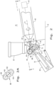
- Dynamic feed roll 70 in accordance with the present invention, is driven directly from threshing rotor 40 as shown in Figs. 2-4 .
- a shaft 78 is supported by and is integral with dynamic feed roll 70.
- bearing assemblies for supporting the threshing rotor 40 and other elements are not shown to simplify the understanding of the present invention, it should be apparent to those skilled in the art that appropriate bearing assemblies may be employed to guide the components, including the threshing rotor, into rotation and fix them in an axial position.
- the threshing rotor 40 rotates about an axis A that is generally parallel to the direction of movement of crop material.
- the dynamic feed roll 70 rotates about an axis B that is at a right angle to axis A.
- Shaft 78 is coupled to a universal joint 80 that extends to a right angle gear box 82 positioned at an elevation above the axis A of threshing rotor 40.
- Right angle gear box 82 may include bevel gears or any other form of gearing that converts the rotational axis through 90°.
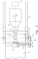
- An output shaft 84 is connected to right angle gear box 82 and extends to an end 86 that is beyond the end of dynamic feed roll 70, particularly illustrated in Fig. 3 .
- the output of shaft 86 is connected to dynamic feed roll 70 by a mechanical connection 88 including an input pulley 92 connected to shaft 84 and an output pulley 94 connected to a shaft 95 that supports dynamic feed roll 70.
- a belt 90 extends over pulleys 92 and 94 and an idler pulley 96 maintains appropriate belt tension for the torque requirements of the dynamic feed roll 70.
- Fig. 2A illustrates an alternative mechanical connection 88 between shaft 84 and shaft 95.
- This mechanical connection 88 includes an input gear 98 coupled to shaft 84 and meshing with an intermediate gear 100 which in turn meshes with an output gear 102 connected to shaft 95.
- the rotational axis is moved at right angles to itself to permit optimum positioning of the dynamic feed roll relative to threshing rotor to position crop material at the optimum position to enable precision and efficient processing to remove grain.
- Fig. 4 shows an alternate arrangement to the universal joint shaft 80 connecting the threshing rotor 40 to the right angle gearbox 82.
- a gear set 106 is positioned having the threshing rotor 40 as an input and the right angle gear box 82 as an output on an input axis that is displaced from the axis A of threshing rotor 42.
- the gear set would have an input gear connected to threshing rotor 40, meshing with an intermediate gear, which in turn, meshes with an output gear connected to right angle gearbox 82.
- This embodiment allows a closer coupling of the dynamic feed roll 70 relative to the input of the threshing rotor 40.
- Fig. 4 also illustrates a pair of threshing rotors 40, one of which drives the dynamic feed roll.
- One of the threshing rotors 40 is driven by the drive train 41.
- the dynamic feed roll 70 is directly driven from the inlet end of the threshing rotor 40 and as such is in complete synchronism with the rotational speed of threshing rotor 40, regardless of what speed range is selected by the threshing rotor power train 41.
- the overall construction is simplified and the unit is able to be more flexibly incorporated in different agricultural harvesters.
Landscapes
- Life Sciences & Earth Sciences (AREA)
- Environmental Sciences (AREA)
- Harvester Elements (AREA)
Applications Claiming Priority (1)
| Application Number | Priority Date | Filing Date | Title |
|---|---|---|---|
| US18/508,958 US20250151663A1 (en) | 2023-11-14 | 2023-11-14 | Feed roll drive for agricultural harvester thresher |
Publications (1)
| Publication Number | Publication Date |
|---|---|
| EP4555852A1 true EP4555852A1 (de) | 2025-05-21 |
Family
ID=93562465
Family Applications (1)
| Application Number | Title | Priority Date | Filing Date |
|---|---|---|---|
| EP24213026.8A Pending EP4555852A1 (de) | 2023-11-14 | 2024-11-14 | Einzugswalzenantrieb für dreschwerk einer landwirtschaftlichen erntemaschine |
Country Status (2)
| Country | Link |
|---|---|
| US (1) | US20250151663A1 (de) |
| EP (1) | EP4555852A1 (de) |
Families Citing this family (1)
| Publication number | Priority date | Publication date | Assignee | Title |
|---|---|---|---|---|
| GB202106242D0 (en) * | 2021-04-30 | 2021-06-16 | Agco Do Brasil Solucoes Agricolas Ltda | Drive system for combine harvester processor |
Citations (3)
| Publication number | Priority date | Publication date | Assignee | Title |
|---|---|---|---|---|
| WO2014141792A1 (ja) * | 2013-03-14 | 2014-09-18 | ヤンマー株式会社 | コンバイン |
| JP2022012790A (ja) * | 2020-07-02 | 2022-01-17 | 株式会社クボタ | 収穫機 |
| US20220346320A1 (en) * | 2021-04-30 | 2022-11-03 | Agco Do Brasil Soluções Agrícolas Ltda. | Drive system for combine harvester processor |
Family Cites Families (18)
| Publication number | Priority date | Publication date | Assignee | Title |
|---|---|---|---|---|
| ES384398A1 (es) * | 1970-08-21 | 1974-06-01 | Penha Maquinas Agricolas | Perfeccionamientos en espigadora desgranadora de maiz. |
| EP0124628A1 (de) * | 1983-05-04 | 1984-11-14 | Klöckner-Humboldt-Deutz Aktiengesellschaft | Mähdrescher mit Axialdreschmaschine |
| US4739773A (en) * | 1986-05-09 | 1988-04-26 | Deere & Company | Feeding arrangement for an axial flow rotary separator |
| GB0106730D0 (en) * | 2001-03-19 | 2001-05-09 | Claas Selbstfahr Erntemasch | Combine harvester |
| US6984171B2 (en) * | 2002-07-19 | 2006-01-10 | Cnh America Llc | Hydro-mechanical threshing rotor control system for an agricultural combine |
| CA2530169C (en) * | 2005-12-15 | 2009-04-14 | Deere & Company | Drive for a crop picking head |
| DE102009002849A1 (de) * | 2008-07-11 | 2010-01-14 | Deere & Company, Moline | Antriebssystem für einen Einzugsförderer einer Erntemaschine |
| DE102010016670A1 (de) * | 2010-04-28 | 2011-11-03 | Claas Selbstfahrende Erntemaschinen Gmbh | Drescheinrichtung für Mähdrescher |
| RU2507735C1 (ru) * | 2012-08-21 | 2014-02-27 | Общество с ограниченной ответственностью "Комбайновый завод "Ростсельмаш" | Устройство привода ротора зерноуборочного комбайна |
| US8781694B1 (en) * | 2013-02-15 | 2014-07-15 | Deere & Company | Combine harvester drive system |
| US9848537B2 (en) * | 2015-04-15 | 2017-12-26 | Agco International Gmbh | Drive system for combine harvester processor |
| US9955628B2 (en) * | 2015-09-25 | 2018-05-01 | Deere & Company | Reversible drive system for an agricultural machine |
| US10028437B2 (en) * | 2015-10-06 | 2018-07-24 | Deere & Company | System for clearing a feeder house and belt pickup |
| US10219436B2 (en) * | 2016-09-30 | 2019-03-05 | Deere & Company | Independent drum drive system for a cotton harvester row unit |
| CN111226610B (zh) * | 2020-02-27 | 2023-10-10 | 江苏大学 | 一种脱粒直径可调的脱粒滚筒、调节方法及联合收割机 |
| US11950528B2 (en) * | 2021-09-23 | 2024-04-09 | Cnh Industrial America Llc | Common drive member for weed seed mill of combine harvester |
| DE102022117780A1 (de) * | 2022-07-15 | 2024-01-18 | Claas Selbstfahrende Erntemaschinen Gmbh | Mähdrescher |
| CN116724763B (zh) * | 2023-08-10 | 2023-10-24 | 山西农业大学高寒区作物研究所 | 一种胡麻用脱粒机 |
-
2023
- 2023-11-14 US US18/508,958 patent/US20250151663A1/en active Pending
-
2024
- 2024-11-14 EP EP24213026.8A patent/EP4555852A1/de active Pending
Patent Citations (3)
| Publication number | Priority date | Publication date | Assignee | Title |
|---|---|---|---|---|
| WO2014141792A1 (ja) * | 2013-03-14 | 2014-09-18 | ヤンマー株式会社 | コンバイン |
| JP2022012790A (ja) * | 2020-07-02 | 2022-01-17 | 株式会社クボタ | 収穫機 |
| US20220346320A1 (en) * | 2021-04-30 | 2022-11-03 | Agco Do Brasil Soluções Agrícolas Ltda. | Drive system for combine harvester processor |
Also Published As
| Publication number | Publication date |
|---|---|
| US20250151663A1 (en) | 2025-05-15 |
Similar Documents
| Publication | Publication Date | Title |
|---|---|---|
| EP3236740B1 (de) | Rückstandhandhabungssystem für eine landwirtschaftliche erntemaschine | |
| EP3228175B1 (de) | Integriertes umkehrsystem mit riemeneingriff | |
| EP3066910A1 (de) | Faltmechanismus für breites weizenschneidwerk | |
| EP3092891B1 (de) | Häcksler für eine landwirtschaftliche erntemaschine | |
| US10405493B2 (en) | Fan in beater to avoid strawhood blockages | |
| AU2015346245B2 (en) | Agricultural elevator supplied by multiple cross augers | |
| US9072220B2 (en) | Agricultural harvester drive line | |
| EP3275304B1 (de) | Querschwingmechanismus für reiniger einer landwirtschaftlichen erntemaschine | |
| EP4555852A1 (de) | Einzugswalzenantrieb für dreschwerk einer landwirtschaftlichen erntemaschine | |
| US10398085B2 (en) | Drive arm for agricultural harvester | |
| EP2996457B1 (de) | Abdeckplatte für eine reinkornschnecke in einem reinigungssystem einer landwirtschaftlichen erntemaschine | |
| EP3120686B1 (de) | Verbindung für eine reinigungseinrichtung einer landwirtschaftlichen erntemaschine | |
| US9504205B2 (en) | Variable stroke cleaning system drive in an agricultural harvester | |
| EP3277071B1 (de) | Antriebssystem für mähdrescherverarbeiter und verfahren zur bereitstellung davon | |
| EP4140287A1 (de) | Zufuhrgehäuse mit unabhängig angetriebenem gesteinsschläger | |
| US10091940B2 (en) | Straw walker arrangement for an agricultural harvester | |
| US12533908B2 (en) | Work vehicle with mounting system for differently sized wheels |
Legal Events
| Date | Code | Title | Description |
|---|---|---|---|
| PUAI | Public reference made under article 153(3) epc to a published international application that has entered the european phase |
Free format text: ORIGINAL CODE: 0009012 |
|
| STAA | Information on the status of an ep patent application or granted ep patent |
Free format text: STATUS: THE APPLICATION HAS BEEN PUBLISHED |
|
| AK | Designated contracting states |
Kind code of ref document: A1 Designated state(s): AL AT BE BG CH CY CZ DE DK EE ES FI FR GB GR HR HU IE IS IT LI LT LU LV MC ME MK MT NL NO PL PT RO RS SE SI SK SM TR |
|
| STAA | Information on the status of an ep patent application or granted ep patent |
Free format text: STATUS: REQUEST FOR EXAMINATION WAS MADE |
|
| 17P | Request for examination filed |
Effective date: 20251121 |