EP4555855A1 - Formsystem zum formen von käse - Google Patents
Formsystem zum formen von käse Download PDFInfo
- Publication number
- EP4555855A1 EP4555855A1 EP24214367.5A EP24214367A EP4555855A1 EP 4555855 A1 EP4555855 A1 EP 4555855A1 EP 24214367 A EP24214367 A EP 24214367A EP 4555855 A1 EP4555855 A1 EP 4555855A1
- Authority
- EP
- European Patent Office
- Prior art keywords
- filtration
- curd
- mixture
- molding system
- serum
- Prior art date
- Legal status (The legal status is an assumption and is not a legal conclusion. Google has not performed a legal analysis and makes no representation as to the accuracy of the status listed.)
- Pending
Links
Images

Classifications
-
- A—HUMAN NECESSITIES
- A01—AGRICULTURE; FORESTRY; ANIMAL HUSBANDRY; HUNTING; TRAPPING; FISHING
- A01J—MANUFACTURE OF DAIRY PRODUCTS
- A01J25/00—Cheese-making
- A01J25/11—Separating whey from curds; Washing the curds
- A01J25/111—Separating whey from curds; Washing the curds by continuous separation
-
- A—HUMAN NECESSITIES
- A01—AGRICULTURE; FORESTRY; ANIMAL HUSBANDRY; HUNTING; TRAPPING; FISHING
- A01J—MANUFACTURE OF DAIRY PRODUCTS
- A01J25/00—Cheese-making
- A01J25/12—Forming the cheese
Definitions
- the invention relates, in general, to the technical field of the food industry and relates in particular to the processing of dairy products, for example to the manufacture of cheese.
- the invention relates more specifically to a molding system, in particular for molding cheese.
- cheesemaking involves a large number of processing steps.
- One of the first operations to be carried out concerns the coagulation of the milk.
- This coagulation step can be achieved in different ways, such as through the action of an enzyme, i.e., rennet, or by fermentation caused by lactic acid bacteria, or, as is often the case, by a combination of the two previous methods. These methods are, of course, not exhaustive.
- the coagulated milk is then drained. This produces the curd and whey.
- the curd is the main ingredient that will produce the cheese; the whey is reintroduced with the curd depending on the desired cheese, or, more rarely, can also be used directly.
- a molding operation consisting of molding the mixture of curd and whey into molds, a mixture which is then refined under predetermined conditions depending on the desired cheese.
- the mixture Before being transferred to the molding machine, the mixture is contained in a tank. It is known that the mixture contains several products that can settle. To avoid any heterogeneity, the tanks are continuously stirred, which greatly reduces heterogeneity.
- the invention aims to overcome the drawbacks of the state of the art and to propose a more precise molding system making it possible to control the standard deviation of the cheeses thus molded.
- a molding system for example for molding cheese, comprising upstream a tank containing a mixture of curd and serum, and downstream a molder, the tank and the molder being connected by a mixture transfer circuit, characterized in that the mixture transfer circuit passes through a mixture filtration device to extract part of the serum and control the proportions of curd and serum in a filtered mixture transferred to the molder.
- the filtration device comprises at least one filtration chamber configured to be traversed by the mixture of curd and serum, a filtrate chamber configured to recover a filtrate from the filtration chamber, and a filter wall between the filtration chamber and the filtrate chamber.
- the filtrate is composed essentially of serum extracted from the curd/serum mixture.
- the molding system is configured so that the mixture of curd and serum passes through the filtration device, preferably through the filtration chamber, continuously.
- the filtration device located upstream of the molder and on the mixture transfer circuit can be continuously passed through by the mixture of curd and serum until it feeds the molder.
- the filtration and filtrate chambers are each delimited by a tubular body, the tubular bodies of the filtration and filtrate chambers being mounted concentrically and coaxially with respect to a longitudinal reference axis, preferably horizontal.
- the filter wall is screened and/or permeable. It can be composed of one or more elements, mobile or fixed, static or dynamic.
- the filtrate chamber is connected to a discharge circuit leading to a discharge tank. This discharge tank allows the serum to be recovered for subsequent processing.
- the molding system comprises back pressure means configured to maintain a back pressure in the filtrate chamber so as not to clog the filter wall.
- the discharge circuit comprises a siphon.
- This siphon is configured so as to maintain a counter-pressure in the filtrate chamber so as to ensure that the filter wall does not clog.
- the evacuation circuit comprises one or more vents, in particular at the high point of the siphon and/or at the top of the curd line so as not to trap air.
- the vent(s) are collected by a pipe which falls back into a collection tank, to allow the vents to be washed after use and the washing product to be returned to the collection tank.
- a connection to a washing circuit capable of supplying the evacuation circuit with a washing liquid can be provided, this washing circuit being able to lead to a collection tank as described previously.
- the filtration regulation means comprise at least one modulating valve.
- the modulating valve is capable of modulating a flow rate of filtrate discharged from the filtrate chamber via the discharge circuit, so as to control the pressure difference between the filtration chamber and the filtrate chamber.
- the cheese molding system comprises at least one curd/whey proportion sensor making it possible to deliver a signal representative of the proportions of curd and whey downstream of the filtration device.
- the operating principle of the turbidimeter is indifferent here, and can implement, for example, optical measurements of diffuse reflection or light absorption, or electrical measurements.
- the curd/whey proportion sensor is unique, at least downstream of the filtration device.
- a sensor can also be positioned upstream of the filtration device to monitor at least one predetermined parameter of the mixture at the inlet of the filtration device.
- This downstream sensor can comprise, for example, a turbidimeter. It can be used to monitor the mixture, the nature of which can, for example, vary depending on the season. The filtration device can therefore also be adjusted based on information measured by the downstream sensor.
- the filtration regulation means are controlled as a function of the signal from the curd/serum proportion sensor.
- the transfer circuit has at least one and preferably at least two control means, such as sights, placed upstream and/or downstream of the filtration device, making it possible to control the proportions of curd and serum in the mixture.
- control means such as sights
- the cheese molding system comprises a vent circuit connected to the transfer circuit and/or to the filtration device.
- the cheese molding system comprises a cleaning circuit for all of the circuits in the system.
- each circuit includes at least one valve, manual or motorized, in order to compartmentalize the cheese molding system if necessary, during cleaning for example.
- the filtration device has a filtration flow rate greater than or equal to 3 m 3 /h, preferably greater than or equal to 6 m 3 /h, and/or less than or equal to 15 m 3 /h, preferably less than or equal to 12 m 3 /h. More preferably, the filtration device is configured to ensure a filtration flow rate substantially equal to 9 m 3 /h, the flow rate being able to vary by plus or minus 0.5 m 3 /h.
- the filtration device is completely removable, for inspection or cleaning for example.
- the filtration device comprises interchangeable connecting parts, allowing adaptation to various architectures of different cheese molding systems.
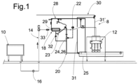
- a cheese molding system 8 comprising a vat 10 configured to contain a mixture of curd and whey, a molder 12 configured to mold the mixture of curd and whey into molds, and a transfer circuit 14 connecting the tank 10 to the molder 12.
- the mixture of curd and whey therefore circulates from the tank 10 located upstream of the transfer circuit 14 to the molder 12 located downstream of the transfer circuit 14, circulating via the transfer circuit 14.
- the molding system 8 must not be confused with the molder 12 : thus the molding system 8 therefore includes the molder 12 (with the tank 10 and the transfer circuit 14 ) but does not constitute the molder 12.
- the tank 10 is here offset from the molder 12 and can be placed at a distance.
- the molder 12 generally comprises a container receiving the curd/whey mixture from the tank 10 via the transfer circuit.
- This container of the molder receiving the mixture of curd and whey can consist of a hopper, a bin or a feed column (not shown).
- the curd/whey mixture circulates from said container of the molder 12 where the curd/whey mixture is stagnant, to a filling end configured to pour the curd/whey mixture into at least one mold. This circulation through the molder 12 is sequenced, depending on the filling of the molds.
- the molding system 8 comprises a filtration device 18 placed on the path of the transfer circuit 14 so that the curd/whey mixture circulating in the transfer circuit 14 from the tank 10 to the molder 12 passes through the filtration device 18.
- the filtration device 18 is separate from the molder 12 and placed on the transfer circuit in which the curd/whey mixture circulates in operation continuously until it feeds the molder 12.
- the molding system 8 includes a transfer pump 16 configured to transfer the curd and whey mixture from the main tank 10 to the molder 12 via the transfer circuit 14.
- the transfer pump 16 is located on the transfer circuit 14, directly downstream of the tank 10 and upstream of the filtration device 18.
- the filtration device 18 makes it possible to reduce the quantity of serum in the mixture of curd and serum coming from the tank 10 if necessary, so that the predetermined proportions of curd and serum of the mixture transferred to the molder 12 are respected.
- a curd/serum proportion sensor 22 (here single) is placed directly downstream of the filtration device 18, or more generally between an outlet of the filtration device 18 and the molder 12. This downstream sensor 22 is arranged directly downstream of the filtration device 18.
- the curd/serum proportion sensor 22 comprises at least one turbidimeter.
- a secondary sensor may be placed directly upstream of the filtration device 18, or more generally between an outlet of the tank 10 and an inlet of the filtration device 18.
- This secondary sensor may preferably comprise at least one turbidimeter such as an optical turbidimeter. It may be a sensor identical to the curd/whey proportion sensor 22 .
- the cheese molding system 8 comprises an evacuation circuit 20 comprising filtration regulation means 24.
- the evacuation circuit 20 makes it possible to create a pressure difference within the filtration device 18 and thus generate the extraction of the excess serum in the mixture within the filtration device 18 then to evacuate it towards an evacuation or recovery tank 25 located for example at the level of the molder 12.
- the serum from cheese making is carefully recovered for recycling.
- This serum can be used, for example, to make other cheeses such as whey cheeses.
- the whey industry has also grown considerably in recent decades, so technological advances in the food industry have helped solve the problems of recycling whey by allowing the extraction of the proteins it contains. contains.
- the serum can thus allow the manufacture of whey powder, whey proteins, whey protein fractions, lactose such as pharmaceutical lactose, milk permeates or even lactose derivatives.
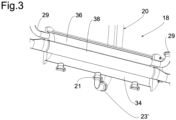
- the evacuation circuit 20 recovers the excess serum via a tapping 21 in the filtration device 18.
- This tapping 21 consists of a connection of a pipe of the evacuation circuit 20 in the filtration device 18, preferably at a vertically low point of the filtration device 18 forming a gravity evacuation of the liquid serum.
- tapping interfaces located vertically under the filtration device 18, in particular under a cylindrical filtrate chamber 36.
- a single tapping is made to connect it to the evacuation circuit 20.
- This tapping 21 extends radially relative to the cylindrical filtrate chamber 36 of the filtration device 18 and also extends locally vertically.
- the molding system 8 is controlled by a control unit (not shown) or automaton to control in particular the filtration of the curd/serum mixture by the filtration device 18.
- the curd/serum proportion sensor 22 (preferably a single downstream curd/serum proportion sensor) is connected to the filtration regulation means 24 and is capable of delivering a signal to the filtration regulation means 24 depending on the proportions of curd and whey in the filtered mixture.
- this secondary sensor can also be connected to the filtration regulation means 24 and is capable of delivering a signal to the filtration regulation means 24 depending on the measured information.
- control unit is dedicated to controlling the molding system 8, which control unit is integrated and communicates with a control unit of the molding machine 12.
- the control unit is configured to control at least at regular intervals, preferably continuously, the values measured by the curd/whey proportion sensor 22 so as to adjust predetermined parameters of the molder 12 directly, i.e. immediately or without delay.
- predetermined parameters may be, for example, the volume of the molding chamber in the molder, commonly called a "former”, the rate and/or the flow rate of the filtration regulation means 24. In the case of the volume of the former, this may be controlled by means of a motorization such as a brushless motor or geared motor, called in English terms "brushless".
- the filtration regulation means 24 comprise for example at least one modulating valve 26 which makes it possible, by its action, to control the quantity of serum evacuated by the evacuation circuit 20.
- the modulating valve 26 here a membrane regulation valve, which makes it possible to exit from the filtration device 18, and more generally from the transfer circuit 14, a necessary flow of serum in order to have at the inlet of the molder 12 a homogeneous curd/serum mixture according to a setpoint entered in the associated automaton or control unit.
- the discharge circuit 20 comprises a siphon 23 located near the tapping 21.
- the pipe of the discharge circuit 20 connected to the filtration device 18 locally has an inverted “U” shaped bend forming a siphon 23.
- the siphon 23 is located at a level vertically above the filtration device 18 corresponding to a predetermined height.
- the height of the siphon 23 is adjustable.
- the siphon 23 makes it possible, in association with the filtration regulation means 24, to maintain a back pressure in the filtration device 18 so as to prevent the curd from clogging said filtration device 18.
- the discharge circuit 20 is configured so that the height of the siphon 23 is variable. Indeed, several parameters external to the molding system 8 are likely to significantly modify the nature of the milk used.
- the milk can be of different natures, for example more or less dry or more or less sticky depending on the season, the protein and fat content of the milk.
- the height of the siphon 23 may be at a low height when the environment is dry; or at a higher height depending on the season. The height of the siphon 23 thus makes it possible to influence the filtration result because it allows a certain control of the clogging of the filter wall, and consequently makes it possible to vary the flow rate.
- the pipe of the evacuation circuit 20 being, on the one hand, connected to the filtration device 18 at a vertically low point of the filtration device 18 forming a gravity evacuation of the liquid serum, and on the other hand having a siphon located at a level vertically above the filtration device 18, said pipe of the evacuation circuit 20 comprises a lower elbow 23' in the shape of a "U" located between said connection and the siphon 23.
- This lower elbow has a removable connection of two portions of pipes so as to allow easy disassembly, or even allow maintenance of the pipe in the event of residues which may remain locally blocked in this lower elbow 23'.
- each tap 21 is connected to a siphon 23, common to the different taps or distinct, mounted in this case in parallel, and each having characteristics similar to the siphon 23 described with reference to the figures.
- the modulating valve 26 forming the filtration regulation means 24 is connected to the evacuation circuit pipe 20 connected to the filtration device 18 via the connection 21.
- the lower elbow 23' and the siphon 23 are located between the connection 21 and the filtration regulation means 24, in particular here the modulating valve 26.
- the modulating valve 26 is located at the outlet of the siphon 23 which is controlled by the turbidimeter 22. In this way, the flow rate of the serum is modulated so as to have a uniform mixture at the outlet of the filtration device 18.
- the cheese molding system 8 also comprises an aeration and maintenance circuit 28.
- the aeration and maintenance circuit 28 is configured to circulate a fluid such as a gas, for example the air within the filtration device 18 by means of vents 29.
- a fluid such as a gas
- the aeration circuit 28 and maintenance circuit allows air to circulate also within the transfer circuit 14 and the evacuation circuit 20.
- air Alternatively to air, other neutral gases compatible with food use could be used.
- Vents 29 are mounted on each of the upstream and downstream flanges 27A, 27B of the filtration device 18, opening inside the filtrate chamber 36, at the top of the siphon 23 and downstream of the sensor 22 relative to the transfer circuit 14 so as not to trap air (see the ventilation circuit 28 on the Figure 1 connecting each of the vents 29 ).
- the vents 29 are collected by a pipe of the ventilation circuit 28 which opens into a recovery tank of the molder 12, because these vents 29 must be washed after use and the return of the washing product is collected by the tank of the molder 12 which takes up washing products.
- a washing circuit 30 also equips the molding system 8.
- the washing circuit 30 is connected to all or part of the transfer circuit(s) 14, filtration 20 and/or aeration 28 in order to circulate a washing liquid therein. Such a washing operation can be carried out at a predetermined frequency.
- the control unit of the molder 12 is configured so as to ensure a repeated washing phase at predefined intervals of the molder 12, preferably of the molder 12 and the filtration device 18 concomitantly.
- a washing line 31 of the washing circuit 30 dedicated to washing the filtration device 18 (see the Figure 1 ) is positioned so as to be connected between, on the one hand, an existing washing line 31' of the molding machine 12, and on the other hand a line of the evacuation circuit 20.
- This cleaning system makes it possible to wash the filtration device 18 against the current.
- all or part of the transfer 14, filtration 20, aeration 28, and washing 30 circuits comprise manual valves 32 in order to allow an operator to intervene quickly and easily on the associated circuit.
- Viewfinders 33 allow an operator to quickly check the appearance of the mixture of curd and whey upstream and/or downstream of the filtration device 18, or more generally along the path of the transfer circuit 14.
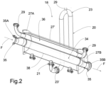
- the filtration device 18 comprises a filtration chamber 34 connected on either side to the transfer circuit 14 by connecting connectors 35, in particular an upstream connecting connector 35A and a downstream connecting connector 35B.
- the filtration chamber 34 is thus crossed by the mixture of curd and serum from an inlet located at the upstream connecting connector 35A where the mixture enters unfiltered to an outlet of the filtered mixture located at the downstream connecting connector 35B.
- the direction of circulation of the curd/serum mixture is illustrated by arrows F on the Figure 2 .
- the filtration chamber 34 is contained in a filtrate chamber 36 which surrounds said filtration chamber 34.
- the filtration chamber 34 extends from one side to the other of said filtrate chamber 36 , passing through it, preferably horizontally.
- This filtration chamber 34 is here of cylindrical shape, and itself contained in the filtrate chamber 36, these two chambers 34, 36 extending coaxially.
- each of these chambers is delimited by a tubular body mounted concentrically and coaxially with respect to a longitudinal reference axis, preferably horizontal.
- Each of these tubular bodies is connected at their upstream and downstream ends by an upstream flange 27A and a downstream flange 27B.
- the upstream flange 27A ensures a rigid connection between the two tubular bodies of the chambers 34, 36 and the downstream flange 27B ensures a rigid connection between the two tubular bodies of the chambers 34, 36.
- These two flanges 27A and 27B are connected together by clamping tie rods 27' extending parallel to the longitudinal reference axis distributed homogeneously around and outside the chambers 34, 36.
- These flanges also form supports at connection interfaces, such as vents 29 and upstream 35A and downstream 35B connection fittings.
- the filtration chamber 34 and the filtrate chamber 36 are separated by a filter wall 38 delimiting the cylindrical surface of the filtration chamber 34.
- the filter wall 38 can be screened or permeable, and made of different materials.
- the mixture of curd and serum, stirred in the tank 10, is transferred from the tank 10 to the molder 12 by the transfer circuit 14 using the transfer pump 16.
- the curd/serum mixture passes through the filtration device 18 and then passes through a portion of the transfer circuit 14 controlled by the curd/serum proportion sensor 22 placed at the outlet of the filtration device 18.
- the curd/serum proportion sensor 22 If the curd/serum proportion sensor 22 measures too high a proportion of serum in the filtered mixture at the outlet of the filtration device 18, it transmits an opening command to open, or open further, the modulating valve 26, which allows the discharge circuit 20 to discharge the filtrate formed from serum to the discharge tank 25, and to reduce the pressure in the discharge circuit 20 upstream of the modulating valve 26, and in the filtrate chamber 36. A pressure difference is established or increases between the filtration chamber 34 and the filtrate chamber 36, which establishes or increases the flow through the filter wall 38, and thus reduces the proportion of serum in the filtered mixture at the outlet of the filtration chamber 34 and the filtration device 18.
- the curd/serum ratio sensor 22 When the curd/serum ratio sensor 22 measures a serum ratio below a predetermined threshold, the curd/serum ratio sensor 22 transmits a closing command to close the modulating valve 26, or close it further.
- the cheese molding system 8 therefore makes it possible to modulate the flow rate of evacuated serum so as to have a homogeneous filtered mixture at the outlet of the filtration device 18.
- a modulating valve 26, here a regulating valve membrane which allows the necessary flow of serum to be released in order to have at the inlet of the mixer 12 a homogeneous curd/serum mixture according to an instruction entered into the machine.
- the curd/whey proportion sensor 22 located downstream of the filtration device 18 relative to the transfer circuit makes it possible to ensure control of the value of proportions predetermined by the control unit. Thanks to the operation of the molding system 8, the proportions of curd and whey in the filtered mixture are thus rebalanced around a predetermined value tending to obtain a homogeneous curd/whey mixture for molding.
- the filtration device 18 comprises vents 29 allowing it to be connected to the ventilation circuit 28.
- the filtration device 18 comprises at least one tapping 21.
- the filtration device 18 is of variable size according to requirements. Furthermore, the connecting fittings 35 forming the inlet and outlet of the filtration device 18 can be of standard or even standardized dimensions, so that said filtration device 18 is adaptable to most existing cheese molding systems 8 .
- the filtration device 18 has a filtration flow rate greater than or equal to 3m 3 /h, preferably greater than or equal to 6 m 3 /h, and/or less than or equal to 15 m 3 /h, preferably less than or equal to 12 m 3 /h.
- the dimensions of the filtration device 18 will preferably be chosen according to the targeted molding flow rate of the molding machine 12. For example, in this embodiment, a length of the filtration device 18, corresponding to an axial length of the filtration chamber 34 but also to an axial length of the filtrate chamber 36 and the filter wall 38, is equal to 950mm, for a molding flow rate of the molding machine 12 of 9m 3 /h.
- the invention thus allows in-line de-wheying implemented by a reliable and precise filtration device 18 , also making it possible to control the proportions of curd and whey in the filtered mixture which is transferred to the molder.
- the filtration device 18 is removable.
- the filtration device 18 being located upstream of the molder, and placed on the transfer circuit from the main tank 10 to the molder 12, it is easy to be able to install such a filtration device 18 both on new installations and on existing installations, without having to intervene on the molder.
- the filtration device 18 according to the invention is therefore complementary to the molder 12 and can be grafted onto any type of molder 12 or more generally any type of molding machine.
- the filtration device 18 is thus independent of the molding machine 12.
- the filtration device 18 thus makes it possible to obtain a uniform mixture (curd/whey) at the outlet of said filtration device 18 and upstream of the molder 12, even before the curd/whey mixture is poured into the container of the molder 12 receiving the mixture of curd and whey.
- the cheese molding system 8 can inject a portion of the filtered serum into the transfer circuit 14 in order to rebalance the proportions of the curd/serum mixture if the curd is present in too large a proportion.
- the filtration device 18 comprises a filtration chamber 34 crossed by the curd/whey mixture, a filtrate chamber 36 and a filtering wall 38 with variable porosity interposed between the filtration chamber 34 and the filtrate chamber 36.
- the variation in porosity can be obtained, for example, by varying a relative positioning of two perforated grids so as to vary the alignment of the perforations of the two grids and, thus, the passage section through the filtering wall 38.
- a control makes it possible to control the relative positioning of the two grids according to the measurements of the proportion of curd and whey. of the mixture filtered by the curd/whey proportion sensor 22.
- This variant requires specific arrangements to avoid clogging of the filter wall.
Landscapes
- Life Sciences & Earth Sciences (AREA)
- Animal Husbandry (AREA)
- Environmental Sciences (AREA)
- Dairy Products (AREA)
Applications Claiming Priority (1)
| Application Number | Priority Date | Filing Date | Title |
|---|---|---|---|
| FR2312764A FR3155413A1 (fr) | 2023-11-20 | 2023-11-20 | Système de moulage, notamment pour le moulage de fromages |
Publications (1)
| Publication Number | Publication Date |
|---|---|
| EP4555855A1 true EP4555855A1 (de) | 2025-05-21 |
Family
ID=89767758
Family Applications (1)
| Application Number | Title | Priority Date | Filing Date |
|---|---|---|---|
| EP24214367.5A Pending EP4555855A1 (de) | 2023-11-20 | 2024-11-20 | Formsystem zum formen von käse |
Country Status (2)
| Country | Link |
|---|---|
| EP (1) | EP4555855A1 (de) |
| FR (1) | FR3155413A1 (de) |
Citations (4)
| Publication number | Priority date | Publication date | Assignee | Title |
|---|---|---|---|---|
| FR1467090A (fr) * | 1965-11-23 | 1967-01-27 | Genvrain Sa | Procédé et appareil permettant la fabrication en continu des fromages à pâtes pressées |
| FR2251257A1 (en) * | 1973-11-16 | 1975-06-13 | Stichting Bedrijven Van Het | Homogeneous large cheeses prodn - by automatically regulating the quantity of curds in the drainage columns |
| FR2430721A1 (fr) * | 1978-07-12 | 1980-02-08 | Bel La Vache Qui Rit Fromage | Procede et appareil de moulage de caille pour la fabrication de fromages de petites dimensions |
| US4332831A (en) * | 1978-02-21 | 1982-06-01 | Universal Foods Corporation | Method of preparing salted cheese curd loaves |
-
2023
- 2023-11-20 FR FR2312764A patent/FR3155413A1/fr active Pending
-
2024
- 2024-11-20 EP EP24214367.5A patent/EP4555855A1/de active Pending
Patent Citations (4)
| Publication number | Priority date | Publication date | Assignee | Title |
|---|---|---|---|---|
| FR1467090A (fr) * | 1965-11-23 | 1967-01-27 | Genvrain Sa | Procédé et appareil permettant la fabrication en continu des fromages à pâtes pressées |
| FR2251257A1 (en) * | 1973-11-16 | 1975-06-13 | Stichting Bedrijven Van Het | Homogeneous large cheeses prodn - by automatically regulating the quantity of curds in the drainage columns |
| US4332831A (en) * | 1978-02-21 | 1982-06-01 | Universal Foods Corporation | Method of preparing salted cheese curd loaves |
| FR2430721A1 (fr) * | 1978-07-12 | 1980-02-08 | Bel La Vache Qui Rit Fromage | Procede et appareil de moulage de caille pour la fabrication de fromages de petites dimensions |
Also Published As
| Publication number | Publication date |
|---|---|
| FR3155413A1 (fr) | 2025-05-23 |
Similar Documents
| Publication | Publication Date | Title |
|---|---|---|
| EP1300167A2 (de) | Vorrichtung und Verfahren zur Bestimmung der Alterung eines Flüssigkeitsfilter | |
| CA3006264A1 (fr) | Procede de traitement de semences | |
| EP4393300B1 (de) | Verfahren und vorrichtung zur herstellung von pizzakäse aus milch | |
| EP0003704B1 (de) | Verfahren und Vorrichtung zum kontinuierlichen Mischen pulverförmiger Stoffe und Flüssigkeiten, insbesondere von Gips und Wasser | |
| EP4555855A1 (de) | Formsystem zum formen von käse | |
| FR3104549A1 (fr) | Installation de conditionnement comprenant des becs de remplissage reliés à des canalisations de retour | |
| CN1086275C (zh) | 用于从浆状物质中分离出乳清的设备 | |
| FR2616043A1 (fr) | Installation de fabrication de produits foisonnes, notamment de cremes glacees | |
| WO2009007577A1 (fr) | Appareil de cristallisation a circulation forcee | |
| DE102015119165B4 (de) | Verfahren zur Klärung eines fließfähigen Produktes mit einer Zentrifuge, insbesondere einem Separator | |
| FR2516356A1 (fr) | Procede de fabrication industrielle en continu de produits et en particulier de produits alimentaires, les moyens de mise en oeuvre de ce procede et les produits en resultant | |
| FR2647349A1 (fr) | Preparation d'une solution a usage medical par dissolution de concentres pulverulents avec recirculation d'une solution | |
| FR2661614A1 (fr) | Procede et dispositif pour preparer une solution de dialyse. | |
| FR2460698A1 (fr) | Machine de dialyse | |
| EP0112260A1 (de) | Die Beherrschung der Fermentierungsevolution während technologischer Arbeit erlaubendes Verfahren zum Salzen von Käsebruchkörnern und Vorrichtung zur Durchführung des Verfahrens | |
| EP4684633A1 (de) | System zum formen eines milchprodukts mit einer vorrichtung zur steuerung eines ventils aus einer druck repräsentativen messung | |
| EP0267864B1 (de) | Vorrichtung zur thermischen Behandlung und Verfahren zur Anwendung derselben bei der Zubereitung von Milchkonfitüre | |
| NL1026381C2 (nl) | Inrichting voor het bereiden van wrongel en voor het toevoeren van de bereide wrongel aan een wrongelverwerkingsinrichting. | |
| EP0959668B1 (de) | Siebvorrichtung zum ableiten von molke aus einer käseform | |
| FR2793110A1 (fr) | Dispositif de moulage d'un melange de caille et de serum, installation de fabrication de fromages, procede de moulage et procede de fabrication de fromages correspondants | |
| FR2704719A1 (fr) | Procédé de moulage de fromages et dispositif pour la mise en Óoeuvre de ce procédé. | |
| FR2971432A1 (fr) | Installation pour traitement d'eau par flottation et procede associe | |
| FR3116695A1 (fr) | Procede et installation de preparation et de distribution d'une composition alimentaire liquide pour animaux d'elevage | |
| CN108601330A (zh) | 用于生产拉伸型凝乳奶酪的凝乳揉捏机器 | |
| EP4623707A1 (de) | Düse zum extrudieren eines eiweiss- und wasserreichen materials sowie system zur kontinuierlichen herstellung eines extrudierten lebensmittelprodukts mit solch einer düse |
Legal Events
| Date | Code | Title | Description |
|---|---|---|---|
| PUAI | Public reference made under article 153(3) epc to a published international application that has entered the european phase |
Free format text: ORIGINAL CODE: 0009012 |
|
| STAA | Information on the status of an ep patent application or granted ep patent |
Free format text: STATUS: THE APPLICATION HAS BEEN PUBLISHED |
|
| AK | Designated contracting states |
Kind code of ref document: A1 Designated state(s): AL AT BE BG CH CY CZ DE DK EE ES FI FR GB GR HR HU IE IS IT LI LT LU LV MC ME MK MT NL NO PL PT RO RS SE SI SK SM TR |
|
| STAA | Information on the status of an ep patent application or granted ep patent |
Free format text: STATUS: REQUEST FOR EXAMINATION WAS MADE |
|
| 17P | Request for examination filed |
Effective date: 20251121 |