EP4555856A2 - Système de levage d'animal - Google Patents
Système de levage d'animal Download PDFInfo
- Publication number
- EP4555856A2 EP4555856A2 EP25169194.5A EP25169194A EP4555856A2 EP 4555856 A2 EP4555856 A2 EP 4555856A2 EP 25169194 A EP25169194 A EP 25169194A EP 4555856 A2 EP4555856 A2 EP 4555856A2
- Authority
- EP
- European Patent Office
- Prior art keywords
- animal
- cradle
- lift
- longitudinal axis
- lift mechanism
- Prior art date
- Legal status (The legal status is an assumption and is not a legal conclusion. Google has not performed a legal analysis and makes no representation as to the accuracy of the status listed.)
- Pending
Links
Images


Classifications
-
- A—HUMAN NECESSITIES
- A01—AGRICULTURE; FORESTRY; ANIMAL HUSBANDRY; HUNTING; TRAPPING; FISHING
- A01K—ANIMAL HUSBANDRY; AVICULTURE; APICULTURE; PISCICULTURE; FISHING; REARING OR BREEDING ANIMALS, NOT OTHERWISE PROVIDED FOR; NEW BREEDS OF ANIMALS
- A01K15/00—Devices for taming animals, e.g. nose-rings or hobbles; Devices for overturning animals in general; Training or exercising equipment; Covering boxes
-
- A—HUMAN NECESSITIES
- A22—BUTCHERING; MEAT TREATMENT; PROCESSING POULTRY OR FISH
- A22B—SLAUGHTERING
- A22B1/00—Apparatus for fettering animals to be slaughtered
-
- A—HUMAN NECESSITIES
- A22—BUTCHERING; MEAT TREATMENT; PROCESSING POULTRY OR FISH
- A22B—SLAUGHTERING
- A22B5/00—Accessories for use during or after slaughtering
-
- A—HUMAN NECESSITIES
- A22—BUTCHERING; MEAT TREATMENT; PROCESSING POULTRY OR FISH
- A22B—SLAUGHTERING
- A22B5/00—Accessories for use during or after slaughtering
- A22B5/06—Slaughtering stands or spreaders for cattle
Definitions
- the invention generally encompasses an animal lift capable of securing an animal, raising the animal vertically to a desired height and rotating the animal along its longitudinal axis up to 180 degrees.
- an animal lift comprising: a lift mechanism; a vertical mast housing at least a portion of the lift mechanism; a horizontal shaft rotatably coupled to the lift mechanism about a longitudinal axis of rotation of the shaft; and a cradle coupled to the shaft, the cradle comprising i) a horizontal support member having a surface for engaging the sternum or underbelly of an animal along the animal's longitudinal axis from head to tail, and ii) a vertical side wall.
- the horizontal support member comprises a flat surface for engaging the sternum or underbelly of an animal.
- the horizontal support member has a rectangular cross-section and is approximately 78 inches long, 5 inches wide and 2.5 inches high (i.e., 78 inches x 5 inches x 2.5 inches).
- the horizontal support member is 50-100 inches long, 3-12 inches wide and 1-4 inches high.
- the cradle further comprises a second vertical sidewall.
- one or two vertical sidewalls are attached to the horizontal support member, or to the horizontal shaft, by one or more attachment members.
- the attachment members are adjustable in length so as to allow the cradle to be widened or narrowed, and/or the vertical side walls to be raised or lowered, as necessary to accommodate an animal.
- the cradle further comprises cushions or spacers, to place between the animal and the vertical sidewalls.
- the spacers are made of a material that conforms to the outer counter of the animal adjacent to the vertical side walls such as foam (e.g., polyethylene or polyurethane foam) or rubber.
- the cradle comprises one or more straps coupled to the support member or the sidewall for restraining the animal.
- the cradle comprises straps for securing the animal.
- the straps may be constructed of any suitable material, including but not limited to nylon.
- the straps are attached to the horizontal support member, one or more of vertical sidewalls, one or more attachment members or the horizontal shaft.
- the lift mechanism comprises a hydraulic lift mechanism.
- the lift mechanism comprises a pneumatic lift mechanism, including a pneumatic cylinder.
- the hydraulic lift mechanism comprises a trolley, a hydraulic cylinder, a lift chain, and mast bearings.
- the hydraulic lift mechanism comprises a hydraulic pump.
- the hydraulic lift mechanism comprises a velocity fuse.
- the animal lift further comprises a hydraulic control valve positioned on the vertical mast. Any known suitable lift mechanism may be employed in the invention in accordance with the knowledge of one of ordinary skill in the art.
- the animal lift further comprises a worm drive for rotating the horizontal shaft about its longitudinal axis of rotation.
- the worm drive is self-locking.
- one end of the horizontal shaft comprises, or is coupled to, a worm wheel.
- the worm screw comprises an axially extending shaft to which a hand crank is attached.
- Another embodiment of the invention comprises an animal lift comprising: a lift mechanism; a vertical mast housing at least a portion of the lift mechanism; and a cradle comprising i) a horizontal shaft rotatably coupled to the lift mechanism about a longitudinal axis of rotation of the horizontal shaft, the horizontal shaft having a surface for engaging the sternum or underbelly of an animal along the animal's longitudinal axis from head to tail, and ii) a vertical side wall.
- FIG. 1 depicts one embodiment of an animal lift 1.
- the animal lift 1 as depicted shows a lift mechanism 2, comprising a trolley 3 with mast bearings 4, a hydraulic cylinder 5, including a cylinder rod 35 with yolk 6 and pulley 7, and a lift chain 8.
- a cable can be used instead of lift chain 8.
- a pneumatic cylinder can be used instead of hydraulic cylinder 5.
- the animal lift 1 further comprises a vertical mast 9 comprising two vertical c-channel members 10 in which the trolley 3 resides and a base 11 onto which the c-channel members 10 and the hydraulic cylinder 5 are secured.
- the c-channel members 10 can be coupled to each other anywhere along their length and/or at the top of the animal lift via a cross member or plate.
- the lift chain 8 is secured to the trolley 3 at one end of the lift chain 12 and to the base 11 at the other end of the lift chain 13 and passes over, and within a groove on, the pulley 7.
- the animal lift 1 as depicted further comprises a horizontal shaft 14 rotatably coupled to the trolley 3 about a longitudinal axis of rotation of the horizontal shaft 14 and a cradle 15 coupled to the horizontal shaft 14.
- the cradle 15 comprises a horizontal support member 16 for engaging the sternum or underbelly of an animal along the animal's longitudinal axis from head to tail.
- animal lift 1 is capable of lifting bovids and swine. Specifically, animal lift 1 is capable of lifting livestock weighing approximately 100-2000 lbs or 100-1000 lbs.
- the horizontal support member 16 has a rectangular cross-section and has dimensions of approximately 78 inches long, 5 inches wide and 2.5 inches high. In another embodiment, the horizontal support member 16 has a width of 3-7 inches or 4-6 inches.
- the cradle 15 as depicted in Figure 1 further comprises two vertical side walls 17 coupled to the support member 16 along its longitudinal axis with attachment members 18. The width and height of the cradle 15 should be sufficient to accommodate the relevant species of animal.
- the attachment members 18 are adjustable in length so as to allow the cradle to be widened or narrowed, and/or the vertical side walls to be raised or lowered, as necessary to accommodate an animal.
- Attachment members 18 are spaced a sufficient distance from one another, and have a sufficiently low profile, to allow an animal to be easily walked into position over horizontal support member 16.
- the animal lift 1 further comprises the use of cushions or spacers (not depicted) to place between the animal and the vertical sidewalls 17.
- the spacers may be made of a material, such as foam (e.g., polyethylene or polyurethane foam) or rubber, that is able to conform to the outer contour of the animal adjacent to the vertical sidewalls 17.
- the base 11 further comprises a pair of wheels 19 that engage the surface on which the animal lift 1 is placed when the animal lift 1 is tilted to a sufficient degree relative to the surface, thereby allowing the animal lift 1 to be moved if desired.
- the base 11 as shown further comprises two base members 20, which extend from the base 11 parallel to the horizontal support member 16. As shown in Figure 1 , the base members 20 extend a distance to approximately match the length of the cradle 15.
- the cradle 15 in the embodiment depicted in Figure 1 further comprises a hinged gate 21 between vertical sidewalls 17 to assist in restraining an animal, especially when the animal lift 1 is in the lowered position and the animal's feet are still contacting the ground.
- Hinged gate 21 may further comprise a portion of a latch 36 for locking or securing hinged gate 21 in the closed position.
- One of the vertical sidewalls 17, or attachment members 18, may comprise the other portion of the latch 36.
- fluid inlets 22 on the hydraulic cylinder 5 through which hydraulic fluid is pumped into the hydraulic cylinder.
- the animal lift 1 further comprises a hydraulic pump for moving fluid into the hydraulic cylinder 5 via fluid inlets 22. Hoses from a hydraulic pump connect to fluid inlets 22.
- a velocity fuse may be placed between a fluid inlet 22 of the hydraulic cylinder 5 and the hydraulic pump in order to prevent the animal lift from being abruptly lowered in the event of failure of the hydraulic system.
- the cradle 15 is comprised of horizontal shaft 14, which engages the sternum or underbelly of an animal along the animal's longitudinal axis from head to tail, instead of horizontal support member 16.
- the vertical side walls 17 of cradle 15 are coupled to the horizontal shaft 14 via attachment members 18.
- the portion of the horizontal shaft 14 that engages the sternum or underbelly of the animal can be flat.
- FIG 2 depicts one aspect of an embodiment of the animal lift 1 that comprises a worm drive 23.
- the worm drive 23 is comprised of a worm screw 24 and a worm wheel 25.
- the worm drive 23 is coupled to the trolley 3.
- One end of the horizontal shaft 14 comprises, or alternatively is coupled to, the worm wheel 25.
- the worm screw 24 further comprises an axially extending shaft to which a hand crank 26 is attached. Turning the hand crank 26 causes the horizontal shaft 14 to be rotated about its longitudinal axis, which in turn causes the cradle 15, along with any animal contained therein, to be longitudinally rotated.
- the worm drive 23 is self-locking.
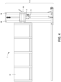
- FIGS 3 and 4 depict one aspect of an embodiment of the animal lift 1.
- a pair of mast bearings 4 engage the inner surface of each c-channel member 10 and allow the trolley 3 to move freely within the vertical mast 9 in the vertical dimension.
- each pair of mast bearings 4 is attached to the trolley 3 at opposite ends of the trolley 3.
- the animal lift 1 is constructed substantially of metal, including but not limited to steel.
- certain components of the animal lift 1, including the trolley 3, mast bearings 4, hydraulic cylinder 5, yolk 6, pulley 7, lift chain 8, vertical mast 9, base 11, horizontal shaft 14, cradle 15, vertical side walls 17, attachment members 18, worm drive 23 and/or hand crank 26 are constructed of steel of such metallurgical properties and manufactured to meet industry-accepted specifications for the anticipated loads and required durability.
- other types of metals including but not limited to aluminum and titanium, can used to construct the components of the animal lift 1, according to the necessary load bearing properties needed for a particular application and as appropriate according to one of ordinary skill in the art.
- other materials such as fiberglass and plastics can be utilized in construction of certain components of the invention, as appropriate according to one of ordinary skill in the art.
- An example of the animal lift 1 being operated is provided by way of the following nonlimiting example.
- An operator of the animal lift 1 lowers the lift mechanism 2 using a hydraulic control valve located on the vertical mast 9.
- the cradle 15 is lowered to a height that allows the animal to easily step over the attachment members 18.
- the animal is positioned so that the cradle's horizontal support member 16 is positioned to engage the sternum or underbelly of the animal along the animal's longitudinal axis from head to tail once the cradle 15 is lifted.
- the animal's left fore and hind legs should be to the left the horizontal support member 16 and the animal's right fore and hind legs should be to the right of the horizontal support member 16.
- the hinged gate 21 is closed. Once the animal is roughly centered along the longitudinal axis of the cradle 15, the hinged gate 21 is closed. Once the animal is comfortable and in position, the operator begins to lift the cradle 15 via operation of a hydraulic control valve (not depicted) located on the vertical mast 9.
- the hydraulic control valve is operably coupled to the hydraulic cylinder 5 and allows the operator to raise and lower the cylinder rod 35, and connected yolk 6 and pulley 7, of the hydraulic cylinder 5 so as to raise and lower the cradle 15.
- the operator raises the cradle to a height where the animal's feet are off of the ground. Once the animal's feet are off of the ground, the animal is examined and/or treated.
- the animal is placed into an anesthetized or sedated state either once the animal's feet are off the ground, or prior to the animal's feet being lifted off of the ground but while supported by the horizontal support member 16.
- the operator then turns the hand crank 26, which rotates the horizontal shaft 14 about its longitudinal axis of rotation.
- the cradle 15 is rotated sufficiently by the operator to deposit the anaesthetized or sedated animal on an examination table in a supine position or on its side.
- the cradle 15 is rotated so that the animal is on its side or in a near supine position while in the cradle 15, and then the animal is slid out of the cradle 15 along one of the vertical sidewalls 17 and onto an examination table by the operator or additional personnel.
Landscapes
- Life Sciences & Earth Sciences (AREA)
- Engineering & Computer Science (AREA)
- Food Science & Technology (AREA)
- Environmental Sciences (AREA)
- Animal Behavior & Ethology (AREA)
- Zoology (AREA)
- Animal Husbandry (AREA)
- Biodiversity & Conservation Biology (AREA)
- Forklifts And Lifting Vehicles (AREA)
- Invalid Beds And Related Equipment (AREA)
- Housing For Livestock And Birds (AREA)
- Catching Or Destruction (AREA)
Priority Applications (1)
| Application Number | Priority Date | Filing Date | Title |
|---|---|---|---|
| EP25169194.5A EP4555856A3 (fr) | 2016-06-21 | 2016-06-21 | Système de levage d'animal |
Applications Claiming Priority (4)
| Application Number | Priority Date | Filing Date | Title |
|---|---|---|---|
| EP16906433.4A EP3471535B1 (fr) | 2016-06-21 | 2016-06-21 | Système de levage d'animal |
| PCT/US2016/038521 WO2017222506A1 (fr) | 2016-06-21 | 2016-06-21 | Système de levage d'animal |
| EP25169194.5A EP4555856A3 (fr) | 2016-06-21 | 2016-06-21 | Système de levage d'animal |
| EP21155999.2A EP3834610B1 (fr) | 2016-06-21 | 2016-06-21 | Système de levage d'animal |
Related Parent Applications (2)
| Application Number | Title | Priority Date | Filing Date |
|---|---|---|---|
| EP21155999.2A Division EP3834610B1 (fr) | 2016-06-21 | 2016-06-21 | Système de levage d'animal |
| EP16906433.4A Division EP3471535B1 (fr) | 2016-06-21 | 2016-06-21 | Système de levage d'animal |
Publications (2)
| Publication Number | Publication Date |
|---|---|
| EP4555856A2 true EP4555856A2 (fr) | 2025-05-21 |
| EP4555856A3 EP4555856A3 (fr) | 2025-10-08 |
Family
ID=60783510
Family Applications (3)
| Application Number | Title | Priority Date | Filing Date |
|---|---|---|---|
| EP16906433.4A Active EP3471535B1 (fr) | 2016-06-21 | 2016-06-21 | Système de levage d'animal |
| EP21155999.2A Active EP3834610B1 (fr) | 2016-06-21 | 2016-06-21 | Système de levage d'animal |
| EP25169194.5A Pending EP4555856A3 (fr) | 2016-06-21 | 2016-06-21 | Système de levage d'animal |
Family Applications Before (2)
| Application Number | Title | Priority Date | Filing Date |
|---|---|---|---|
| EP16906433.4A Active EP3471535B1 (fr) | 2016-06-21 | 2016-06-21 | Système de levage d'animal |
| EP21155999.2A Active EP3834610B1 (fr) | 2016-06-21 | 2016-06-21 | Système de levage d'animal |
Country Status (7)
| Country | Link |
|---|---|
| EP (3) | EP3471535B1 (fr) |
| BR (1) | BR112018075795B1 (fr) |
| CA (1) | CA3028077C (fr) |
| DK (1) | DK3471535T3 (fr) |
| ES (1) | ES2877705T3 (fr) |
| PL (1) | PL3834610T3 (fr) |
| WO (1) | WO2017222506A1 (fr) |
Families Citing this family (3)
| Publication number | Priority date | Publication date | Assignee | Title |
|---|---|---|---|---|
| BE1026589B1 (nl) * | 2018-09-04 | 2020-03-30 | Clercq Jorick De | Kar voor het behandelen van biggen in een kraamstal van een varkenskwekerij |
| CN109588330B (zh) * | 2018-11-08 | 2021-06-01 | 南京幸庄科技创新产业园管理有限公司 | 一种能够在不惊动母羊的情况下抬起羔羊的取暖箱 |
| CN112616890A (zh) * | 2020-12-01 | 2021-04-09 | 民勤中天羊业有限公司 | 一种屠宰剥皮用提升操作平台 |
Family Cites Families (7)
| Publication number | Priority date | Publication date | Assignee | Title |
|---|---|---|---|---|
| US1234733A (en) | 1917-02-05 | 1917-07-31 | James W Corington | Hog-holding machine. |
| US3541888A (en) * | 1969-04-14 | 1970-11-24 | Warn Belleview Inc | Mechanical power transmitting mechanism |
| US5441016A (en) * | 1992-11-30 | 1995-08-15 | Ricketts; Tod | Giraffe handling chute |
| US5299658A (en) * | 1993-06-17 | 1994-04-05 | Hunter Engineering Company | Automatic hydraulic lift circuit |
| AUPO925097A0 (en) * | 1997-09-18 | 1997-10-09 | Korjenic, Hamid | Shearing lifting jack |
| AU2006235761B1 (en) * | 2005-11-08 | 2007-03-01 | Australian Wool Innovation Ltd | Shearing platform |
| US8051807B2 (en) * | 2007-03-14 | 2011-11-08 | Zinpro Corporation | Sow chute and hoist |
-
2016
- 2016-06-21 EP EP16906433.4A patent/EP3471535B1/fr active Active
- 2016-06-21 BR BR112018075795-0A patent/BR112018075795B1/pt active IP Right Grant
- 2016-06-21 CA CA3028077A patent/CA3028077C/fr active Active
- 2016-06-21 EP EP21155999.2A patent/EP3834610B1/fr active Active
- 2016-06-21 WO PCT/US2016/038521 patent/WO2017222506A1/fr not_active Ceased
- 2016-06-21 ES ES16906433T patent/ES2877705T3/es active Active
- 2016-06-21 PL PL21155999.2T patent/PL3834610T3/pl unknown
- 2016-06-21 DK DK16906433.4T patent/DK3471535T3/da active
- 2016-06-21 EP EP25169194.5A patent/EP4555856A3/fr active Pending
Also Published As
| Publication number | Publication date |
|---|---|
| DK3471535T3 (da) | 2021-06-28 |
| WO2017222506A1 (fr) | 2017-12-28 |
| EP3834610A1 (fr) | 2021-06-16 |
| BR112018075795B1 (pt) | 2021-12-14 |
| EP3471535B1 (fr) | 2021-03-31 |
| ES2877705T3 (es) | 2021-11-17 |
| EP3471535A1 (fr) | 2019-04-24 |
| PL3834610T3 (pl) | 2025-09-22 |
| CA3028077A1 (fr) | 2017-12-28 |
| EP4555856A3 (fr) | 2025-10-08 |
| CA3028077C (fr) | 2022-07-19 |
| EP3834610B1 (fr) | 2025-04-09 |
| EP3471535A4 (fr) | 2019-05-15 |
| BR112018075795A2 (pt) | 2019-03-26 |
Similar Documents
| Publication | Publication Date | Title |
|---|---|---|
| US8051807B2 (en) | Sow chute and hoist | |
| EP3834610B1 (fr) | Système de levage d'animal | |
| US4201157A (en) | Portable animal handling unit | |
| US4055148A (en) | Animal holding clamp apparatus | |
| US3208432A (en) | Examination and treatment table for veterinary use | |
| US5441016A (en) | Giraffe handling chute | |
| US20170267153A1 (en) | Livestock trailer with enclosed elevator platform | |
| US8240276B1 (en) | Squeeze chute apparatus | |
| US20190076228A1 (en) | Large animal treatment table | |
| KR20110100413A (ko) | 환자 이송용 기능성 테이블 | |
| US5461736A (en) | Portable hydraulic lift step stool for raising handicapped patients to an elevated location | |
| US9999489B1 (en) | Animal lifting table with offloading ramp | |
| US9992976B2 (en) | Animal lift | |
| US20080223309A1 (en) | Sow chute and hoist | |
| US20080054580A1 (en) | Glaser equipment transporter | |
| US7044086B2 (en) | Animal raising and lowering system | |
| US10561483B2 (en) | Tiltable cart | |
| US20230189752A1 (en) | Devices, methods and systems for restraining, transporting and manipulating animals | |
| CN221060936U (zh) | 一种可调节保定架 | |
| CN221106118U (zh) | 一种牛舍的保定架 | |
| RU153205U1 (ru) | Тележка-подъемник для перемещения больных | |
| Aschbacher | An adjustable metabolism stall for cattle | |
| CN210019967U (zh) | 一种适用于x线检查的多功能升降转运车 | |
| RU2499696C2 (ru) | Подъемное устройство безопасной погрузки животных в транспортные средства и разгрузки с них | |
| WO2026015038A1 (fr) | Dispositif de levage de chien |
Legal Events
| Date | Code | Title | Description |
|---|---|---|---|
| PUAI | Public reference made under article 153(3) epc to a published international application that has entered the european phase |
Free format text: ORIGINAL CODE: 0009012 |
|
| STAA | Information on the status of an ep patent application or granted ep patent |
Free format text: STATUS: THE APPLICATION HAS BEEN PUBLISHED |
|
| AC | Divisional application: reference to earlier application |
Ref document number: 3471535 Country of ref document: EP Kind code of ref document: P Ref document number: 3834610 Country of ref document: EP Kind code of ref document: P |
|
| AK | Designated contracting states |
Kind code of ref document: A2 Designated state(s): AL AT BE BG CH CY CZ DE DK EE ES FI FR GB GR HR HU IE IS IT LI LT LU LV MC MK MT NL NO PL PT RO RS SE SI SK SM TR |
|
| PUAL | Search report despatched |
Free format text: ORIGINAL CODE: 0009013 |
|
| AK | Designated contracting states |
Kind code of ref document: A3 Designated state(s): AL AT BE BG CH CY CZ DE DK EE ES FI FR GB GR HR HU IE IS IT LI LT LU LV MC MK MT NL NO PL PT RO RS SE SI SK SM TR |
|
| RIC1 | Information provided on ipc code assigned before grant |
Ipc: A01K 1/08 20060101AFI20250903BHEP Ipc: A01K 13/00 20060101ALI20250903BHEP Ipc: A01K 15/00 20060101ALI20250903BHEP Ipc: A01K 15/04 20060101ALI20250903BHEP Ipc: A22B 1/00 20060101ALI20250903BHEP Ipc: A22B 5/00 20060101ALI20250903BHEP Ipc: A22B 5/06 20060101ALI20250903BHEP |
|
| STAA | Information on the status of an ep patent application or granted ep patent |
Free format text: STATUS: REQUEST FOR EXAMINATION WAS MADE |
|
| 17P | Request for examination filed |
Effective date: 20260407 |