EP4555917A1 - Verfahren und vorrichtung zur bestimmung mindestens eines brechungswerts eines auges - Google Patents
Verfahren und vorrichtung zur bestimmung mindestens eines brechungswerts eines auges Download PDFInfo
- Publication number
- EP4555917A1 EP4555917A1 EP23210416.6A EP23210416A EP4555917A1 EP 4555917 A1 EP4555917 A1 EP 4555917A1 EP 23210416 A EP23210416 A EP 23210416A EP 4555917 A1 EP4555917 A1 EP 4555917A1
- Authority
- EP
- European Patent Office
- Prior art keywords
- person
- eye
- visual stimulus
- value
- radial line
- Prior art date
- Legal status (The legal status is an assumption and is not a legal conclusion. Google has not performed a legal analysis and makes no representation as to the accuracy of the status listed.)
- Withdrawn
Links
Images


Classifications
-
- A—HUMAN NECESSITIES
- A61—MEDICAL OR VETERINARY SCIENCE; HYGIENE
- A61B—DIAGNOSIS; SURGERY; IDENTIFICATION
- A61B3/00—Apparatus for testing the eyes; Instruments for examining the eyes
- A61B3/02—Subjective types, i.e. testing apparatus requiring the active assistance of the patient
- A61B3/028—Subjective types, i.e. testing apparatus requiring the active assistance of the patient for testing visual acuity; for determination of refraction, e.g. phoropters
- A61B3/036—Subjective types, i.e. testing apparatus requiring the active assistance of the patient for testing visual acuity; for determination of refraction, e.g. phoropters for testing astigmatism
-
- A—HUMAN NECESSITIES
- A61—MEDICAL OR VETERINARY SCIENCE; HYGIENE
- A61B—DIAGNOSIS; SURGERY; IDENTIFICATION
- A61B3/00—Apparatus for testing the eyes; Instruments for examining the eyes
- A61B3/02—Subjective types, i.e. testing apparatus requiring the active assistance of the patient
- A61B3/028—Subjective types, i.e. testing apparatus requiring the active assistance of the patient for testing visual acuity; for determination of refraction, e.g. phoropters
- A61B3/032—Devices for presenting test symbols or characters, e.g. test chart projectors
Definitions
- the present invention refers to a method, a computer program, and an apparatus for determining at least one refractive value of an eye of a person and to a related method for producing at least one ophthalmic lens for an eye of a person.
- Keirl A.W. and Christie C. see above, further describe a so-denoted "fan-and-block-technique", which is frequently implemented in sight-test units to determine the best sphere, the axis and magnitude of astigmatism.
- a fan is used to determine a presence of astigmatism and its principal axes, while blocks are used in conjunction with cylindrical lenses in order to neutralize the astigmatism.
- the fan-and-block-technique may comprise the following two elements:
- Test Chart 2020 by Thomson Software Solutions, which is available under https://www.thomson-software-solutions.com/test-chart-xpert-3di/ comprises a plurality of test charts and vision tests, binocular vision tests and refraction stimuli.
- a software has to be installed on personal computer, a monitor mounted on a wall, a screen viewing distance entered, and a calibration test performed. Included is a fan and block test for identifying and correcting astigmatism.
- mean bearing fixing astigmatism was not significantly different from cross-cylinder astigmatism, but did have higher test-retest variability (p ⁇ 0.05). Acuity with bearing fixing and cross-cylinder corrections did not significantly differ in average value or repeatability.
- virtual refraction systems e.g. Vision Optimizer a System with refraction elements above the head of the patient
- digital infinite refraction e.g. Vision-S 700 Essilor
- guided refraction systems e.g. Chronos Topcon or VASRTM Vision Inc
- in-store refraction units or table-top concepts mobile phone subjective refraction approaches such as used in conjunction with head mounted VR-goggles (e.g. EyeNetra) or smartphone apps including a desktop monitor (e.g., Opternative) provide state-of-the art solutions.
- CREAL SA 1024 Ecublens, Switzerland, presents under the title "Whitepaper: CREAL'S digital light field", which is available under https://creal.com/technology/ a light-field display configured for displaying virtual images in desired focal distances.
- EP 3 730 038 A1 discloses a system and method for interactively measuring ocular refractive errors, addition and power of reading glasses without need of an optical component that would change optical vergence of a target.
- the system can measure the distance from a user's eyes to either or both border of interval of clear vision, for one orientation or two perpendicular orientations. The measurements together with the user's age can be used to estimate sphero-cylindrical refraction, addition and power of reading glasses.
- the system can use different sizes, directions and colors of targets which can change with said distance or user interaction.
- US 2020/0397279 A1 discloses methods, systems, and devices for measuring eye refraction with a mobile device application without a lens.
- An exemplary method includes measuring a distance between a patient and a mobile device, presenting to the patient one or more visual targets sized and shaped to represent perfect vision such as by using Vernier targets or grating targets, instructing the patient to indicate whether the patient can accurately read the visual targets and, if not, to move closer to the mobile device until the patient can accurately read the visual targets, calculating a vision prescription for the patient based on the visual targets and a final distance between the patient and the mobile device, and displaying the vision prescription for the patient.
- the present invention relates to a method for determining at least one refractive value of an eye of a person.
- the method comprises the following steps, which may be performed in the given order. A different order, however, may also be feasible. Further, two or more of the method steps may be performed simultaneously. Thereby the method steps may at least partly overlap in time. Further, the method steps may be performed once or repeatedly. Thus, one or more or even all of the method steps may be performed once or repeatedly.
- the method may comprise additional method steps not listed herein.
- the method for determining at least one refractive value of an eye of a person comprises the following steps:
- the present method is configured for determining at least one refractive value of an eye of a person.
- a different term such as “subject”, “test person”, “user”, or “wearer” may also be applicable.
- the person may perform the method autonomously; however, she may be accompanied by a further person supporting the person, wherein the further person may, preferably, selected from at least one of a parent, a nurse, an optician, an apprentice, an ophthalmologist, a optics sales person, a technical photographer.
- a further person which may accompany the person may also be conceivable.
- the term "determining”, or any grammatical variation thereof refers to a process configured for generating at least one representative result.
- the representative result may be determined in a process, wherein at least one step of the process may be selected from at least one of a measurement step; an evaluation step; or a displaying step.
- For determining the representative result at least one measurement may be performed. Data generated in this measurement may be evaluated.
- the representative result may be data retrieved in the evaluation process.
- the representative result may be displayed.
- the representative result comprises outcome data comprising at least one refractive value of the eye of the person.
- the outcome data may be displayed on at least one monitor.
- the terms “refraction” or “refractive” refer to a bending of incident light entering the interior of the eye of the person via a pupil in a manner that the incident light may, in particular owing to a form of the eye, not be focused appropriately on the retina of the eye, resulting particularly in a blurred vision of the person.
- the term “refractive value” is a number indicating a strength of the bending of incident light.
- the present method is configured for determining at least one astigmatic effect of an eye of a person, wherein the term "astigmatic effect" refers to a condition in which an optical system comprising one eye of the person forms two individual line images of a point object, typically, as a result of a toricity of at least one refracting surface of the eye of the person.
- the refraction causes that light which impinges on an eye is distributed on the retina in an unequal fashion, which may, in particular, result in a distorted and/or blurred vision of the person.
- the method may be implemented for being performed for exactly one eye of the person; it may be repeated for a further eye of the person, wherein the other eye of the person can be covered, particularly initiated by a corresponding graphical user interface, which may be configured for assisting the person in this respect.
- the at least one refractive value of the eye of the person comprises values of:
- the term “spherical power” refers to a value of a back vertex power of an ophthalmic lens, including the lens of the eye of the person, or for a back vertex power in one of two meridians of an astigmatic-power lens, depending on a principal meridian chosen for reference.
- the term “principal meridian” is one of two mutually perpendicular meridians of the astigmatic-power lens that are parallel to the two line foci.
- the first principal meridian algebraically has the lower vertex power
- the second principal meridian algebraically has the higher vertex power
- the term “cylindrical power” refers to an algebraic difference between the power of the principal meridian chosen for reference subtracted from the power of the other perpendicular meridian.
- the term “cylinder axis” refers to a direction of the principal meridian of a lens whose vertex power is chosen for reference and, therefore, corresponds to the meridian direction of the astigmatism of the eye of the person.
- the term “dioptric power” comprises both the spherical power and the cylindrical power of the ophthalmic lens, if a prismatic effects are neglected.
- an ophthalmic lens For a purpose of exerting an influence on the at least one refractive value of an eye of a person, an ophthalmic lens may be used.
- the term “ophthalmic lens” refers to an optical lens which is configured for a purpose of at least one of a measurement, a correction or a protection of the eye.
- the term “spectacle lens” relates to a type of ophthalmic lens, which is worn in front of, but not in contact with, the eyeball
- the term “contact lens” relates to a further type of ophthalmic lens, which is worn in in contact with the eyeball.
- further types of ophthalmic lenses are feasible.
- the method for determining at least one refractive value of an eye of a person may be a computer-implemented method.
- the term "computer-implemented method” refers to a method, which involves at least one device, specifically a computer, particularly connected to a computer network.
- a plurality of devices may be connected, particularly for transmitting data, via a network by using at least one connection interface at any one of the devices of the plurality of devices.
- the computer-implemented method may be implemented as at least one computer program that may be provided on a storage medium carrying the computer program, whereby at least one step of the method may be performed by using the at least one computer program.
- any step of the method is performed using the at least one computer program.
- the at least one computer program may be accessible by an apparatus which may be adapted for performing the method via a network, in particular via an in-house network, via internet, or via a cloud.
- a visual stimulus is displayed to an eye of a person.
- the term "visual stimulus” refers to a graphical presentation of an item, particularly an item that is known or reasonably to be expected by the person skilled in the art to be considerably suitable for determining at least one refractive value of an eye of a person. Such an item can also be denoted by the term "optotype".
- the visual stimulus may particularly be suitable if it is perceptible by the person, especially due to a contrast between the visual stimulus and a background that allows the eye of the person to distinguish between the visual stimulus and the background.
- the visual stimulus comprises a plurality of concentric radial lines.
- the term "line" refers to a straight two-dimensional curve having a length which exceeds a lateral extension of the line, preferably by a factor of at least 10, more preferred of at least 25, especially of at least 50.
- the line may, preferably, be an continuous elongated line; however, using a dashed line may also be feasible.
- the line may be black or may exhibit at least one color.
- the line may exhibit a uniform lateral extension, or the lateral extension may vary along the length of the line.
- the line may, preferably, exhibit a uniform contrast; however, the contrast may slightly vary along the length of the line. Further embodiments of the line may also be feasible.
- the term "radial” refers to a direction originating at a central point and departing from the central point in a straight manner.
- the central point may be a "center” in a sense that a particular line may originate at the central point.
- the central point functions as a "center” in a sense that a particular line may not originate at the central point but in a particular distance from the central point.
- the term "concentric” relates to an arrangement of a plurality of radial lines, wherein each radial line is oriented with respect to an identical central point.
- the plurality of the radial lines may, preferably, originate at the same particular distance from the central point; however, using different distances from the central point for some or all radial lines may also be feasible.
- each concentric radial line as comprised by the visual stimulus has a different angular value with respect to the center of the visual stimulus.
- angular value refers to a number indicating a relative direction to a predetermined radial direction.
- the concentric radial lines may be arranged as a fan having a starburst pattern around the center of the visual stimulus.
- fan is used in a sense as disclosed by Keirl A.W. et al., see above, in connection with the so-denoted “fan-and-block-technique", which results in a so-denoted "starburst pattern" which appears to originate from the center of the visual stimulus.
- the visual stimulus may be a monochrome starburst pattern; however, using a chromatic starburst pattern may also be feasible.
- the concentric radial lines may be arranged in equidistant steps; however, using different angular distances between adjacent lines for some or for all concentric radial lines may also be feasible.
- the visual stimulus may comprise 6, 8, 9, 12, 15, 18, 24, 30, 36, 48, 60, 72, 90, 96, or 120 of concentric radial lines, thus, resulting in an angular distance of 3°, 3.75°, 4°, 5°, 6°, 7.5°, 10°, 12°, 15°, 20°, 24°, 30°, 40°, 45°, or 60°, respectively.
- using a different number of concentric radial lines may also be feasible.
- a projection device configured for displaying the visual stimulus to the eye of the person according to step a) may be used.
- the term "projection device” refers to an electronic visual display device designated for a presentation of the visual stimulus, wherein the electronic visual display device is configured for projecting each radial line of the visual stimulus at a particular defocus plane to the eye of the person.
- the projection device may be located in front of the person in a manner that it may face an eye of the person.
- at least one additional optical element especially at least one of an optical mirror or a beam splitter, may also be conceivable.
- at least one holding element may, additionally, be attached to the projection device, wherein the at least one holding element may be configured for maintaining a position of the projection device with respect to an eye of the person.
- the projection device may, preferably, be comprised by at least one of
- the term “desktop computer” refers to a computer in a housing suitable for use as a workstation computer on top of a desk but, sometimes, also placed below a desk.
- the term “mobile communication device” refers to an electronic device configured for communicating with at least one further electronic device, which can be carried by the person and, may thus, move together with the person.
- the mobile communication device comprises at least one of a screen and a processing device and, optionally, a camera, wherein a mobile operating system running on the processing unit may be configured for facilitating a use of software, internet, and multimedia functionalities, in particular by using a wireless communications protocol, such as Wi-Fi or Bluetooth.
- the processing device may comprise an evaluation device as described below in more detail.
- the mobile communication device may comprise at least one sensor which may, in particular, be selected from at least one of a motion sensor, a gyro sensor, an accelerometer, a proximity sensor, a magnetometer, or a barometer; however, using a further kind of sensor may also be feasible.
- the mobile communication device may comprise at least one actuator, in particular a vibration motor.
- the mobile communication device may comprise at least one microphone configured for recording at least one of an acoustic response by the person.
- the mobile communication device may be selected from at least one of:
- the term “smartphone” refers to a mobile phone having computer functionalities and connectivity and may, additionally, comprise at least one of a camera, a sensor or an actuator.
- the term “smart watch” refers to an electronic wristwatch which has computer functionalities and connectivity and may comprise at least one of a sensor or an actuator.
- the term “smart glass” refers to a wearable spectacle lens having computer functionalities and connectivity, wherein, in addition to the visual reception of the wearer through the ophthalmic lens, further information may be provided.
- augmented reality glass refers to a controllable ophthalmic lens being configured for providing access to augmented reality for a wearer.
- the term “virtual reality headset” refers to a head-mounted display designed for providing access to virtual reality for a wearer.
- the term “laptop” refers to a particular type of computer having a screen being movably attached to a housing, wherein the screen can be folded onto the housing.
- the term “tablet” refers to a portable, flat touch-screen computer.
- the term “smart television” refers to a television set which, further, comprises computer functionalities and connectivity.
- each radial line is projected at a particular defocus plane to the eye of the person.
- each of at least two radial lines, more preferred each radial line is projected at a different defocus plane to the eye of the person; however, at least two radial lines may be projected at the same defocus plane to the eye of the person as long as sufficient radial lines for the purposes of the present invention may be projected at different defocus planes to the eye of the person.
- the terms "focal plane” or "focus plane” refer to an imaginary plane, which is perpendicular to an optic axis and passes through a focal point.
- the term "defocus plane” relates to a further imaginary plane, which is spatially displaced with respect to a focus plane in a parallel manner. Accordingly, each radial line as projected at a different defocus plane is recognized by the eye of the person as a virtual three-dimensional image having a different distance to the eye of the person. Displaying the radial lines in this manner corresponds to generating a different dioptric effect by each radial line to the eye of the person. As a consequence, each radial line provides a particular dioptric power to the eye of the person.
- the term "dioptric step” relates to a fixed difference between two dioptric powers as expressed in diopters.
- the dioptric step may be selected from a value of 0.125 D, 0.25 D, 0.5 D, 0.75 D, or 1.0 D; however, using a different value for the dioptric step may also be feasible.
- the projection device may, preferably, be configured for using a virtual display technique, wherein the projection device may, particularly, be selected from at least one of:
- the term "light field” refers to vector function indicating an amount of light propagating in a particular direction at a particular spatial point.
- a "light-field display” is designed for generating a rendered 3D model or an imaged scene that as obtained from a plurality of viewpoints, in particular by using a moving camera or an array of cameras.
- the term "holographic optical element” relates to an optical element configured for generating at least one holographic image or "hologram” by using optical diffraction.
- optical diffraction refers to a propagation of light in presence of an obstacle denoted as “optical diffraction element", such as a slit or a diffraction grating.
- optical diffraction element such as a slit or a diffraction grating.
- holographic display For a purpose of generating a volume hologram, a known “holographic display” can be used.
- the term “retinal laser beam projection” relates to a device which is configured for projecting a laser beam onto the retina of the eye of the person. As a result, the person directly recognizes a visual stimulus which is generated at the retina of the eye by using a laser beam.
- a reaction by the person to the visual stimulus is recorded.
- reaction refers to an action of the person in response to a visual stimulus displayed to an eye of the person.
- recording or any grammatical variation thereof relates to a process of recognizing a reaction of the person by observing a behavior of the person, which may be expressed by a measurable signal, in particular an electronic signal or an optical signal, which may be provided by at least one input element as described below in more detail.
- At least one input element configured for recording a reaction by the person to the visual stimulus according to step b) may be used.
- the term "input element” refers to an element which is configured for monitoring an occurrence of an event by providing or interrupting a monitoring signal when the event occurs.
- the at least one input element may be configured for recording at least one of:
- recording the reaction by the person to the visual stimulus can be initiated by using a graphical user interface, which may be configured for assisting the person in this respect, as described below in more detail.
- the term "tactile response” refers to a manual touching of a mechanical or a virtual element by the person.
- a mechanical button, or a virtual button can, particularly, be used, wherein the virtual button may be displayed on the touchscreen, preferably placed on the projection device close to a rotation element, preferably a mechanical rotation element or a virtual rotation element, as described below in more detail, but not overlapping it.
- a combined rotation and input element which may comprise the function of both the rotation element and the input element, can be used in this fashion.
- touching the combined rotation and input element in a particular fashion may be considered as recording the desired reaction by the person to the visual stimulus.
- recording that the combined rotation and input element has been stopped for a predefined time interval can be interpreted as indicating the desired reaction by the person to the visual stimulus.
- different types of input elements configured for recording the at least one tactile response may also be conceivable.
- the term "acoustic response" refers to receiving a sound generated by the person, wherein the sound is interpreted as indicating the desired reaction by the person to the visual stimulus.
- at least one microphone can be used; however, using a different type of element may also be feasible.
- the term “gesture” refers to a particular behavior of the person which can be interpreted as the desired reaction by the person to the visual stimulus.
- at least one monitoring device especially selected from a camera, a motion sensor, or an eye tracker, can be used.
- at least one front camera placed in the vicinity of the projection device, especially above the projection device may be preferred; however, using a different arrangement and type of the monitoring device may also be conceivable.
- the reaction by the person to the visual stimulus indicates that a particular radial line at a particular angular value has an appearance of maximum sharpness to the eye of the person.
- the term “indicating” or any grammatical variation thereof relates to a process of providing a piece of information that an event is occurring or has just occurred.
- the term “appearance” refers to a process of recognizing an event by a person.
- the term “sharpness” relates to a contrast between an object and an area surrounding the object at least partially.
- the term “maximum” refers to an extreme value indicating a highest value in a set of values.
- the term “minimum” refers to a further extreme value indicating a lowest value in a set of values.
- the at least one refractive value of an eye of the person is determined by evaluating the reaction by the person to the visual stimulus.
- the term "determining" or any grammatical variation thereof refers to a process of generating at least one representative result, such as a plurality of representative results.
- the term "evaluating" or any grammatical variation thereof refers to applying at least one algorithm to extract at least one piece of information from the at least one reaction by the person to the visual stimulus.
- the at least one algorithm may be configured for determining the at least one refractive value of an eye of the person by evaluating a relationship between the angular value of a particular radial line at a particular angular value and the reaction by the person to the appearance of the maximum sharpness to the eye of the person of the particular radial line according to a scheme.
- the piece of information that the eye of the person can recognize the particular radial line being projected at the particular defocus plane as sharp is used for determining the at least one refractive value by applying at least one appropriate algorithm.
- the method according to the present invention may, further, comprise the following additional step: d) rotating the visual stimulus by the person, wherein the angular value of each radial line with respect to the center of the visual stimulus is altered, whereby a rotated visual stimulus is obtained.
- recording the reaction by the person to the visual stimulus according to step b) may, particularly, comprise indicating that a particular radial line at a particular angular value in the rotated visual stimulus has the appearance of maximum sharpness to the eye of the person and wherein determining the at least one refractive value of the eye of the person according to step c) further comprises evaluating the reaction by the person to the rotated visual stimulus.
- step d) the visual stimulus is rotated by the person, whereby a rotated visual stimulus is obtained.
- rotating or any grammatical variation thereof refers to a process of moving an object in a manner that a center of the object is maintained, while an angular value of the object is, concurrently, altered.
- rotating the visual stimulus comprises maintaining the center of the visual stimulus and, concurrently, altering the angular value of each radial line.
- the projection device as described above or below in more detail may further be configured for displaying the rotation of the at least one visual stimulus by the at least one angular value. As consequence of rotating the visual stimulus in this manner, each radial line which provides a particular dioptric power to the eye of the person is moved around the center of the visual stimulus.
- At least one rotation element configured for rotating the visual stimulus by the person by the at least one angular value according to step d) may be used.
- rotation element refers to an element which is configured for rotating the visual stimulus by the person to obtain the rotated visual stimulus in a manner that the center of the visual stimulus maintained, while the angular value of each radial line with respect to the center of the visual stimulus is, concurrently, altered.
- the at least one rotation element may be selected from at least one of a mechanical rotation element or a virtual rotation element.
- the term "mechanical rotation element” relates to an element, which can be manually touched by the person to induce a rotation of an object, wherein at least one of an intensity, a duration, or a direction of a touching the element by the person may be configured for inducing at least one of a velocity or a direction of the rotation of the object. Further, removing a hand of the person from the mechanical rotation element may induce a stop of the rotation of the object.
- the mechanical rotation element may be selected from at least one of a turning knob, a button, or a switch.
- the mechanical rotation element may be placed in a vicinity of the projection device in order to maintain the concentration of the person towards the visual stimulus, while the person is rotating the visual stimulus by actively executing a mechanical action.
- the term "virtual rotation element” relates to a virtual element displayed on a screen, especially on the same projection device which is used for displaying the at least one visual stimulus.
- the screen may be a touchscreen, wherein the virtual element can be manually touched by the person on the touchscreen to induce a rotation of an object, wherein at least one of an intensity, a duration, or a direction of a touching the virtual element by the person may be configured for inducing at least one of a velocity or a direction of the rotation of the object. Further, removing a hand of the person from the virtual rotation element may induce a stop of the rotation of the object.
- the virtual rotation element may be placed on the projection device close to the visual stimulus, but not overlapping it, in order to maintain the concentration of the person towards the visual stimulus, while the person is virtually rotating the visual stimulus on the projection device.
- the virtual rotation element may be selected from at least one of a virtual turning knob, a virtual button, or a virtual switch, which may be displayed on the screen to resemble to the person a mechanical equivalent selected from a turning knob, a button, or a switch.
- a different kind of virtual element may also be feasible.
- the virtual rotation element may refer to an arbitrary element which may be configured for voice control by receiving an acoustic response by the person, wherein the acoustic response may be configured for inducing or stopping a rotation of the object and for adjusting a velocity or a direction of the rotation of the object.
- the virtual rotation element may be feasible.
- the reaction by the person to the visual stimulus provides the piece of information that the person recognizes that a contrast in a particular radial line, which is displayed to the eye of the person at a particular angular value, shows a contrast which is higher than or as high as the other radial lines comprised by the visual stimulus. Since each radial line is projected according to step a) at a particular defocus plane to the eye of the person, whereby a particular dioptric power is provided to the eye of the person, and since the visual stimulus is rotated by the person according to step d) to obtain the visual stimulus, the reaction by the person to the visual stimulus provides the piece of information that the eye of the person can see sharp the particular radial line, which is projected at the particular defocus plane.
- the at least one refractive value of the eye of the person may comprise at least one value of at least one refraction ellipse, preferably all following values of the at least one refraction ellipse:
- dioptric power is used as defined above. Further information about the refraction ellipse can be found below in Figure 2 and the corresponding description.
- step d) may comprise determining concurrently
- the method according to the present invention may, further, comprise the following additional steps:
- the term "further” indicates that at least one process is repeated at least once, preferably once.
- a further rotated visual stimulus in addition to step d) is obtained, wherein the angular value of each radial line with respect to the center of the visual stimulus is, compared to step d), additionally altered.
- a further reaction by the person to the further rotated visual stimulus is recorded according to step f) in a manner that it indicates that a further particular radial line at a further particular angular value also has the appearance of maximum sharpness to the eye of the person.
- the further particular angular value is selected to be perpendicular to the particular angular value as recorded at step d).
- the at least one further refractive value of the eye of the person is determined according to step g) by further evaluating both the reaction by the person to the rotated visual stimulus as recorded at step d) and the further reaction by the person to the further rotated visual stimulus as recorded at step f).
- step g) may, preferably, comprise determining
- Determining the at least one refractive value of an eye of the person may be performed in accordance with a predefined scheme, however, artificial intelligence, in particular machine learning, may also be applied, especially by using a neuronal network.
- machine learning refers to a process using artificial intelligence to automatically generate a statistical model for at least one of classification or regression.
- a machine learning algorithm configured for generating the desired model based on a large number of training data sets can, preferably, be used.
- the machine learning algorithm can be a supervised algorithm or a self-learning algorithm.
- the machine learning algorithm can use or comprise a neural network, preferably, developed into a trained neural network by using the at least one training data set.
- the neural network may comprise at least one element selected from hierarchical decision trees, Hough forest, regression forest, Convolutional Neural Network (CNN), Deep Neural Network (DNN) Residual Neural Network, Pixel-wise Voting, Pixel-wise Fusion Network, Deep learning.
- CNN Convolutional Neural Network
- DNN Deep Neural Network
- Residual Neural Network Pixel-wise Voting
- Pixel-wise Fusion Network Deep learning.
- using at least one other artificial intelligence method such as a kernel method, especially a Support Vector Machine (SVM), may also be conceivable.
- SVM Support Vector Machine
- At least one evaluation device configured for determining at least one refractive value of the eye of the person by evaluating the reaction by the person to the visual stimulus according to step b) may be used.
- evaluation device refers to a processing device which is configured for executing the at least one algorithm as described above, wherein the processing of the at least one algorithm may be performed in at least one of a consecutive or a parallel manner.
- all method steps can be performed by using a single processing device, such as a computer, especially a desktop computer or a mobile communication device, as disclosed above and below in more detail.
- the single processing device may be configured for exclusively performing at least one computer program, in particular at least one line of computer program code configured for executing at least one algorithm, as used in at least one of the methods according to the present invention.
- the computer program as executed on the single processing device may comprise all instructions causing the computer to carry out the at least one of the methods according to the present invention.
- at least one method step can be performed by using at least one remote processing device, especially selected from at least one of a server or a cloud server, which may, preferably, not be located at the site of the person when executing the at least one method step.
- the computer program may comprise at least one remote portion to be executed by the at least one remote processing device to carry out the at least one method step.
- the evaluation device may comprise at least one communication interface configured for at least one of forwarding or receiving data to or from the at least one remote portion of the computer program.
- the term "communication interface" refers a transmission channel configured for a transmission of data.
- the communication interface may be arranged as a unidirectional interface configured for forwarding at least one piece of data into a single direction, from at least one input interface to the processing device, or from the evaluation device to at least one output interface.
- the communication interface may be arranged as a bidirectional interface configured for forwarding at least one piece of data into one of two directions, from the evaluation comprising to both an input interface and an output interface, or vice versa.
- the term "input interface” refers to an apparatus which is configured for receiving at least one piece of data, specifically the data related to the reaction by the person as described above or below in more detail.
- the data can, preferably, be generated as input data by using a graphical user interface, and forwarded to the evaluation device for determining the desired data related to the at least one refractive value of an eye of the person.
- graphical user interface or “GUI” refer to a type of input interface which is configured to receive the desired data from a graphical interaction with a user.
- the graphical interaction may comprise presenting at least one of a menu or graphical icons, preferably including the visual stimulus, the virtual rotation element and the input element, on a screen to the user, and recording a reaction of the person by using the at least one input element.
- at least one touchscreen configured to provide access to inputting at least one piece of data may be used.
- the term "guidance” refers to at least one piece of information provided to the person, preferably in a visual, acoustic or tactile fashion, which the at least one piece of information provides at least one of a recommendation to the person or a confirmation of an action performed by the person, specifically during a reaction of the person.
- a graphical user interface having at least one further function may also be conceivable.
- the term "output interface" refers to a further device which is configured to provide at least one output file comprising at least one further piece of data, specifically the desired data related to the at least one refractive value of an eye of the person.
- the processing device may, preferably, be configured to provide the data related to the at least one refractive value of an eye of the person the by using a different or, preferably, the same graphical user interface, which is configured for displaying the data comprised by the output file to the user.
- the output file may be transferred to a further processing device of the person, a further person, or entity, particularly selected from an optician, an ophthalmologist, or an insurance company, particularly for reviewing the data, and initiating a process for producing at least one spectacle lens or for approving the data and enabling the initiating of the process for producing the at least one spectacle lens
- a further processing device of the person e.g., a further person, or entity, particularly selected from an optician, an ophthalmologist, or an insurance company, particularly for reviewing the data, and initiating a process for producing at least one spectacle lens or for approving the data and enabling the initiating of the process for producing the at least one spectacle lens
- a computer program for determining at least one refractive value of an eye of a person comprising instructions which, when the program is executed by a computer, cause the computer to carry out the method for determining at least one refractive value of an eye of a person.
- the term "computer program” refers to at least one executable instruction for at least one programmable device, specifically a computer, preferably a sequence of executable instructions, for processing and/or solving of at least one function and/or at least one task and/or at least one problem by using at least one programmable apparatus or device, specifically a computer, preferably for performing some or all steps of any one of the methods as described within the present invention.
- instructions are combined to a computer program code and/or provided in a programming language.
- a computer program is typically processed by using a processing device comprised by the at least one computer.
- the computer program may be running on the computer.
- the computer program code may be provided on a data storage medium or a separate device such as an optical storage medium, e.g., on a compact disc, directly on a computer or data processing device, or via a network, such as via an in-house network or via internet.
- the present invention relates to a data carrier signal carrying outcome data which are generated by a method for determining at least one refractive value of an eye of a person which comprises generating the outcome data.
- data carrier signal refers to an electronic signal comprising information.
- the data carrier signal may be provided on a computer-readable storage medium.
- computer-readable storage medium specifically may refer to a non-transitory data storage means, such as a hardware storage medium having stored thereon computerexecutable instructions.
- the present invention relates to a method for producing at least one ophthalmic lens for an eye of a person, which comprises the following steps:
- the data carrier signal or the method for producing at least one ophthalmic lens, reference may be made to the method for determining at least one refractive value of an eye of a person as disclosed elsewhere herein.
- the present invention relates to an apparatus for determining at least one refractive value of an eye of a person.
- the apparatus comprises:
- the apparatus may, further, comprise
- the apparatus may, further, comprise at least one distance meter.
- distance meter refers to a device which is configured for determining at least one distance between an eye of the person and the at least one projection device configured for the displaying the at least one visual stimulus to an eye of the person.
- a value determined for the at least one distance between an eye of the person and the at least one projection device may be used in determining the at least one refractive value of the corresponding eye of the person.
- the at least one distance meter is comprised by the desktop computer or the mobile communication device, particularly wherein at least one front camera of the mobile communication device configured for determining the at least one distance between an eye of the person and the at least one projection device may be used.
- at least one front camera of the mobile communication device configured for determining the at least one distance between an eye of the person and the at least one projection device may be used.
- further embodiments for the at least one distance meter may also be conceivable.
- the apparatus can be provided in an arbitrary fashion as long as it is accessible to the person being desirous of determining at least one refractive value of an eye.
- the apparatus can be provided in a room belonging to practice of an ophthalmologist or to a shop of an optician or optometrist.
- the apparatus can be provided in a kiosk or a part thereof.
- the term "kiosk” refers to an unmanned, free-standing structure which houses at least one of an interactive terminal or a video monitors, typically located in a public place, especially a shopping center or a retail store, being accessible by person for a use of the person.
- the apparatus may be placed inside the kiosk and a person being desirous of determining at least one refractive value of an eye can approach the apparatus and perform the method as described elsewhere herein.
- the at least one refractive value can be determined in a fashion which is applicable on a global scale to all kinds of persons, whereby difficulties with communication or compliance can be avoided as far as possible.
- providing the apparatus in a different fashion may also be conceivable.
- the method, computer program, and apparatus for determining at least one refractive value of an eye of a person as disclosed herein advantageously, allow determining at least one refractive value of an eye of a person, especially with regard to an astigmatic power and an astigmatic axis, by applying a reliable, easy and intuitive approach.
- the at least one refractive value can be determined without requiring an ophthalmologist, optician or optometrist, a set of measuring glasses or a sophisticated device, such as an autorefractive device, designated for this purpose.
- the at least one refractive value can be determined in a fashion which is applicable on a global scale to all kinds of persons over a broad range of cognitive skills, thereby avoiding difficulties with communication or compliance as far as possible.
- the terms “have”, “comprise” or “include” or any arbitrary grammatical variations thereof are used in a non-exclusive way. Thus, these terms may refer to both a situation in which, besides the feature introduced by these terms, no further features are present in the entity described in this context and to a situation in which one or more further features are present.
- the expressions “A has B”, “A comprises B” and “A includes B” may both refer to a situation in which, besides B, no other element is present in A (i.e. a situation in which A solely and exclusively consists of B) and to a situation in which, besides B, one or more further elements are present in entity A, such as element C, elements C and D or even further elements.
- the terms “preferably”, “more preferably”, “particularly”, “more particularly”, or similar terms are used in conjunction with optional features, without restricting alternative possibilities.
- features introduced by these terms are optional features and are not intended to restrict the scope of the claims in any way.
- the invention may, as the skilled person will recognize, be performed by using alternative features.
- features introduced by "in an embodiment of the invention” or similar expressions are intended to be optional features, without any restriction regarding alternative embodiments of the invention, without any restrictions regarding the scope of the invention and without any restriction regarding the possibility of combining the features introduced in this way with other features of the invention.
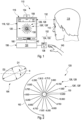
- Figure 1 illustrates a preferred embodiment of an apparatus 110 for determining at least one refractive value of an eye 112 of a person 114.
- the at least one refractive value of both eyes 112 of the person 114 can, preferably, be determined in a consecutive fashion.
- the apparatus 110 can be provided in a room belonging to practice of an ophthalmologist or to a shop of an optician or optometrist. As an alternative, the apparatus 110 can be provided in a kiosk or a part thereof. In this manner, the person 114 has easy access to the apparatus 110 at a public place, especially a shopping center or a retail store, allowing determining the at least one refractive value on a global scale to all kinds of persons 114 without difficulties with communication or compliance as far as possible.
- the exemplary apparatus 110 of Figure 1 comprises - without limiting the scope of the invention - an electronic device 116 having a projection device 118 which is configured for displaying a visual stimulus image 120 to the user 114.
- the electronic device 116 comprises a monitor 122 and a corresponding desktop computer 124.
- a touchscreen comprised by a mobile communication device can be used, wherein the mobile communication device may, preferably, be selected from at least one of a smartphone, a smart watch, a smart glass, an augmented reality glass, a virtual reality glass, a laptop, a tablet, or a smart television.
- the mobile communication device may, preferably, be selected from at least one of a smartphone, a smart watch, a smart glass, an augmented reality glass, a virtual reality glass, a laptop, a tablet, or a smart television.
- further alternatives may also be feasible.
- Figures 1 to 5 schematically illustrated the exemplary visual stimulus 120 having a plurality of concentric radial lines 126, 126', ..., wherein each radial line 126, 126', ... has a different angular value 128, 128', ... with respect to a center 130 of the visual stimulus 120.
- the concentric radial lines 126, 126', ... are arranged as a fan having a starburst pattern around the center 130 of the visual stimulus in a sense as disclosed by Keirl A.W. et al., see above, in connection with the so-denoted "fan-and-block-technique.
- a so-denoted "starburst pattern” is provided, which appears to originate from the center 130 of the visual stimulus 120.
- the visual stimulus 120 is a monochrome starburst pattern; however, a chromatic starburst pattern may also be feasible.
- each radial line 126, 126', ... directs to the center 130 of the visual stimulus 120, it originates in a particular distance from the center 130 of the visual stimulus 120.
- concentric radial lines 126, 126', ... are arranged in equidistant steps; however, using different angular distances between adjacent radial lines 126, 126', ... may also be feasible.
- the exemplary visual stimulus 120 as depicted in Figures 1 to 5 comprises 18 concentric radial lines radial lines 126, 126', ..., which results in an angular distance of 20° between adjacent radial lines 126, 126', ...; however, using a different number of concentric radial lines 126, 126', ... may also be feasible. Still, various further embodiments of the visual stimulus 120 are conceivable.
- each radial line 126, 126', ... is projected at a particular defocus plane to the eye 112 of the person 114, thereby providing a particular dioptric value to the eye 112 of the person 114.
- the eye 112 of the person 114 is located at a constant distance 132 from the projection device 118, it recognizes each radial line 126, 126', ... as having a particular distance from the eye 112 of the person 114, wherein the particular distance from the eye 112 of the person 114 may, preferably, be different for each radial line 126, 126', ....
- a dioptric step of 0,75 D is used as a difference between the defocus planes for adjacent radial lines radial lines 126, 126', ...; however, using a different value for the dioptric step may also be feasible.
- the projection device 118 may, preferably, be configured for using a virtual display technique, particularly be selected from a light-field, a holographic optical element, and/or a retinal laser beam projection; however, using a different type of projection device may also be conceivable.
- each radial line 126, 126', ... of the visual stimulus 120 as presented on the projection device 118 to the eye 112 of the person 114 according to Figures 1 and 2 is a continuous elongated line having a uniform lateral extension and an identical sharpness
- the eye 112 of the person 114 recognizes a difference in sharpness, depending on the at least one refractive value of the eye 112 of the person 114 and a relative orientation of the visual stimulus 120 with respect to the eye 112 of the person 114, as schematically depicted in Figures 3 to 5 .
- the apparatus 110 further comprises a rotation element 134.
- the rotation element 134 is configured for rotating the visual stimulus 120 by the person 114 in a manner that the angular value of each concentric radial line 126, 126', ... with respect to the center 130 of the visual stimulus is altered, whereby a rotated visual stimulus 136 is obtained.
- the rotation element 134 is a turning knob 138, which can be touched by the hand 140 of the person 114 in order to induce a rotation of the visual stimulus 120 as displayed on the projection device 118.
- an intensity, a duration and/or a direction of the touching of the rotation element 134 by the hand 140 of the person 114 induces a velocity and/or a direction of the rotation of the visual stimulus 120.
- a different kind of mechanical rotation element in particular a button, or a switch, may also be feasible.
- the mechanical rotation element may be placed in a vicinity of the projection device 118 in order to facilitate the concentration of the person 114 towards the visual stimulus 120 while the person 114 is using the rotation element.
- a virtual rotation element may be displayed on the projection device 118 close to the visual stimulus 120, but not overlapping it.
- the virtual rotation element may be a virtual turning knob, a virtual button, or a virtual switch, resembling the mechanical equivalent to the person 134; however, using a different kind of virtual element may also be feasible.
- the virtual rotation element may be configured for voice control by the person 114, especially by recording an acoustic response by the person 114.
- the apparatus 110 may comprise a microphone 142 as schematically depicted in Figure 1 .
- still further embodiments of the virtual rotation element are conceivable.
- the apparatus 110 further comprises an input element 150.
- the input element 150 is configured for recording a reaction by the person 114 to the visual stimulus 120 or, preferably, to the rotated visual stimulus 136 indicating that the particular radial line 144 at the particular angular value 146 appears to the eye 112 of the person 114 at maximum sharpness 148 as schematically illustrated in Figure 4 .
- the input element 150 and the rotation element 134 constitute a combined rotation and input element 152, which is configured here for providing functions of both the rotation element 134 and the input element 150.
- the turning knob 138 can further be pressed by the hand 140 of the person 114 in order to indicate the desired reaction by the person 114 to the rotated visual stimulus 136 expressing that the particular radial line 144 at the particular angular value 146 appears at maximum sharpness 148 to the eye 112 of the person 114.
- removing the hand 140 of the person 114 from the turning knob 138 may, initially, induce a stop of the rotation of the visual stimulus 120 and, after a predefined time interval, be interpreted as the desired reaction by the person 114 to the visual stimulus 120 or, preferably, to the rotated visual stimulus 136.
- using a different type of input element 150 may also be feasible.
- an acoustic response by the person 114 and/or a gesture of the person 140 can be used for recording the desired reaction by the person 114 to the visual stimulus 120 or, preferably, to the rotated visual stimulus 136.
- the microphone 142 as comprised by the exemplary apparatus 110 of Figure 1 can, further, be used.
- the apparatus 110 may comprise a monitoring device, in particular a front camera 154 as schematically depicted in Figure 1 ; however, using a different arrangement and type of the monitoring device may also be conceivable.
- the front camera 154 may be used as a camera, a motion sensor, or an eye tracker. Further, the front camera 154 may be used as a distance meter for determining the distance 132 between the eye 112 of the person 114 and the projection device 118.
- the apparatus 110 further comprises an evaluation device 156.
- the evaluation device 156 is configured for determining the at least one refractive value of the eye 112 of the person 114 by evaluating the reaction by the person 114 to the visual stimulus 120 or, preferably, to the rotated visual stimulus 136.
- the evaluation device 156 may, preferably be comprised by the desktop computer 124.
- a further local processing device and/or a remote processing device (not depicted here), in particular a server or a cloud server, may also be feasible.
- a graphical user interface 158 configured for assisting the person 114 at determining the at least one refractive value of the eye 112 of the person 114 may be displayed on the projection device 118.
- the graphical user interface 158 may show at least one piece of information about the person 114, the at least one refractive value of the eye 112 of the person 114 and/or one or more steps of related procedure for determining the at least one refractive value of the eye 112 of the person 114.
- at least one piece of information about rotating the visual stimulus 120 and/or the reaction by the person 114 to the rotated visual stimulus 136 can be provided to the person 114 or initiated by providing the at least one corresponding piece of information to the person 114.
- the apparatus 110 further comprises a loudspeaker 160, which may be configured to support the graphical user interface 158 by providing the at least one piece of information to the person 114 in an acoustic fashion.
- Figures 2 illustrates an enlarged version of the same visual stimulus 120 as displayed on the projection device 118 as shown in Figure 1 .
- the visual stimulus 120 comprises 18 concentric radial lines radial lines 126, 126', ... in an angular distance of 20° between adjacent radial lines 126, 126', ..., which have been projected by using a virtual display technique, whereby 18 different defocus planes ranging from +2.25 D to -10.50 D in 0.75 D dioptric steps are used.
- the visual stimulus 120 can be rotated by the person 14 by using the rotation element 134.
- the visual stimulus 120 is used according to the method as disclosed herein to directly determine at least one value, preferably all values, of a refraction ellipse 164 configured to describe the refractive value s of the eye 112 of the person 114, wherein the values of the refraction ellipse 164 as further depicted there comprise:
- each concentric radial line 126, 126', ... represents an individual refractive requirement for the eye 112 of the person 114, is rotated to the particular angular value 146 to appear under maximum sharpness 148 to the eye 112 of the person 114.
- the contrast within the visual stimulus 120 may, predominantly, be a function of a broadening of a width of each line 126, 126', ..., which can be minimized by rotating the visual stimulus 120 in a manner that the rotated visual stimulus 136 is may be oriented parallel to the angular value ⁇ with regard to the first spatial direction D1 in order to compensate the maximum value of the dioptric power or, alternatively, parallel to an angular value 90° + ⁇ with regard to the first spatial direction D1 in order to compensate the minimum value of the dioptric power.
- the orientation of the refraction ellipse 164 and one of its meridians can be measured by rotating the visual stimulus 120 alone without being visually affected by the astigmatism of the eye 112 of the person 114.
- the visual stimulus 120 may be, further, rotated to maximize the contrast for a further particular radial line 166 at a further particular angular value 168 to appear under maximum sharpness 148 to the eye 112 of the person 114, wherein the further particular angular value 168 in the further rotated visual stimulus 170 is perpendicular to the particular angular value 146 as previously determined.
- both the major axis and the minor axis of the refraction ellipse 164 configured to describe the refractive values of the eye 112 of the person 114 can been determined.
- Figure 3 illustrates an example of a recognition of the visual stimulus 120 by the eye 112 of the person 114.
- the corresponding eye 112 of the person 114 recognizes the lines closer to the circle of least confusion of the person 114 less blurry compared to other lines; however, no line can be recognized with maximum sharpness 148 by the eye 112 of the person 114 under a rotation angle of the starburst pattern of the visual stimulus 120 as depicted in Figure 3 .
- the person 114 now rotates the starburst pattern as comprised by the visual stimulus 120 until the rotated visual stimulus 136 is obtained, wherein the particular line 144 at the particular angular value 146 appears at maximum sharpness 148 to the eye 112 of the person 114 as schematically illustrated in Figure 4 .
- the person 114 further rotates the starburst pattern of the already rotated visual stimulus 136 until the further rotated visual stimulus 170 is obtained, wherein the further particular radial line 166 at the further particular angular value 168 appears under maximum sharpness 148 to the eye 112 of the person 114.
- the major axis and the minor axis of the refraction ellipse 164 configured to describe the refractive values of the eye 112 of the person 114 can be determined in this manner.
- Figure 6 schematically illustrates a preferred embodiment of a method 210 for producing an ophthalmic lens 212 for the eye 112 of the person 114 according to the present invention.
- At least one refractive value 216 of the eye 112 of the person 114 is determined by using a method 218 for determining the at least one refractive value 216 of the eye 112 of the person 114.
- the method 218 comprises a displaying step 220 pursuant to step a), according to which the visual stimulus 120 is displayed to the eye 112 of the person 114.
- the visual stimulus 120 comprises the plurality of the concentric radial lines 126, 126', ..., wherein each radial line 126, 126', ... has the different angular value 128, 128', ... with respect to the center 130 of the visual stimulus 120.
- the method 218 may, further, comprise an optional rotating step 222 pursuant to step d), according to which the visual stimulus 120 may be rotated by the person 114, wherein the angular value 128, 128', ... of each radial line 126, 126', ... with respect to the center 130 of the visual stimulus 120 may be altered, whereby the rotated visual stimulus 136 may be obtained, such as exemplarily depicted in Figure 4 .
- the method 218 for determining the at least one refractive value 216 of the eye 112 of the person 114 comprises a recording step 224 pursuant to step b), according to which the reaction by the person 114 to the visual stimulus 120 or, preferably, to the rotated visual stimulus 136 is recorded.
- the method 218 comprises a determining step 226 pursuant to step c), according to which the at least one refractive value 216 of the eye 112 of the person 114 is determined by evaluating the reaction by the person 114 to the visual stimulus 120 or, preferably, to the rotated visual stimulus 136.
- the method 218 may further comprise a further rotating step 228 pursuant to step e), according to which the visual stimulus 120 is further rotated by the person 114, such as exemplarily depicted in Figure 5 , whereby the further rotated visual stimulus 170 is obtained, wherein the angular value 128, 218', ... of each radial line 126, 126', ... with respect to the center 130 of the visual stimulus 120 is further altered.
- the method 218 may further comprise a further recording step 230 pursuant to step f), according to which a further reaction by the person 114 to the further rotated visual stimulus 170 is recorded.
- further reaction by the person 114 to the further rotated visual stimulus 170 indicates that a further particular radial line 166 at a further particular angular value 168 has the appearance of maximum sharpness 148 to the eye 112 of the person 114.
- the further particular angular value 168 is perpendicular to the particular angular value 146 as recorded according to the recording step 224 pursuant to step d).
- the method 218 may further comprise a further determining step 232 pursuant to step g), according to which at least one further refractive value 216 of the eye 112 of the person 114 is determined by evaluating the further reaction by the person 114 to the further rotated visual stimulus 170.
- the at least one further value as determined here by applying the further determining step 232 is attributed to the at least one refractive value 216 of the eye 112 of the person 114 as determined above in the determining step 226 pursuant to step d).
- the method 210 for producing the at least one ophthalmic lens 212 for the eye 112 of the person 114 comprises a generating step 234 according to method step (ii), wherein at least one geometrical model 236 of the at least one ophthalmic lens 212 is generated by using the at least one refractive value 216 of the eye 112 of the person 114 as determined by using the refraction determining step 214 pursuant to method step (i).
- the method 210 for producing the at least one ophthalmic lens 212 for the eye 112 of the person 114 comprises a processing step 238 according to method step (iii), wherein at least one lens blank 240 is processed according to the at least one geometrical model 236 of the at least one ophthalmic lens 212, whereby the at least one ophthalmic lens 212 is produced.
Landscapes
- Life Sciences & Earth Sciences (AREA)
- Health & Medical Sciences (AREA)
- Medical Informatics (AREA)
- Biophysics (AREA)
- Ophthalmology & Optometry (AREA)
- Engineering & Computer Science (AREA)
- Biomedical Technology (AREA)
- Heart & Thoracic Surgery (AREA)
- Physics & Mathematics (AREA)
- Molecular Biology (AREA)
- Surgery (AREA)
- Animal Behavior & Ethology (AREA)
- General Health & Medical Sciences (AREA)
- Public Health (AREA)
- Veterinary Medicine (AREA)
- Eye Examination Apparatus (AREA)
Priority Applications (2)
| Application Number | Priority Date | Filing Date | Title |
|---|---|---|---|
| EP23210416.6A EP4555917A1 (de) | 2023-11-16 | 2023-11-16 | Verfahren und vorrichtung zur bestimmung mindestens eines brechungswerts eines auges |
| PCT/EP2024/082522 WO2025104270A1 (en) | 2023-11-16 | 2024-11-15 | Method and apparatus for determining at least one refractive value of an eye |
Applications Claiming Priority (1)
| Application Number | Priority Date | Filing Date | Title |
|---|---|---|---|
| EP23210416.6A EP4555917A1 (de) | 2023-11-16 | 2023-11-16 | Verfahren und vorrichtung zur bestimmung mindestens eines brechungswerts eines auges |
Publications (1)
| Publication Number | Publication Date |
|---|---|
| EP4555917A1 true EP4555917A1 (de) | 2025-05-21 |
Family
ID=88837094
Family Applications (1)
| Application Number | Title | Priority Date | Filing Date |
|---|---|---|---|
| EP23210416.6A Withdrawn EP4555917A1 (de) | 2023-11-16 | 2023-11-16 | Verfahren und vorrichtung zur bestimmung mindestens eines brechungswerts eines auges |
Country Status (2)
| Country | Link |
|---|---|
| EP (1) | EP4555917A1 (de) |
| WO (1) | WO2025104270A1 (de) |
Citations (5)
| Publication number | Priority date | Publication date | Assignee | Title |
|---|---|---|---|---|
| WO2003090612A1 (en) * | 2002-04-26 | 2003-11-06 | Queensland University Of Technology | Optometry measurement device |
| WO2014195951A1 (en) * | 2013-06-06 | 2014-12-11 | Ofer Limon | System and method for measurement of refractive error of an eye based on subjective distance metering |
| EP3730038A1 (de) | 2019-04-25 | 2020-10-28 | VisionApp Solutions S.L. | Computerimplementiertes verfahren und system zur interaktiven messung von brechungsfehlern des auges, addition und leistung einer lesebrille |
| WO2020243771A1 (en) * | 2019-06-07 | 2020-12-10 | SPEQS Limited | Eye test |
| US20200397279A1 (en) | 2018-02-22 | 2020-12-24 | The Schepens Eye Research Institute, Inc. | Measuring eye refraction |
-
2023
- 2023-11-16 EP EP23210416.6A patent/EP4555917A1/de not_active Withdrawn
-
2024
- 2024-11-15 WO PCT/EP2024/082522 patent/WO2025104270A1/en active Pending
Patent Citations (5)
| Publication number | Priority date | Publication date | Assignee | Title |
|---|---|---|---|---|
| WO2003090612A1 (en) * | 2002-04-26 | 2003-11-06 | Queensland University Of Technology | Optometry measurement device |
| WO2014195951A1 (en) * | 2013-06-06 | 2014-12-11 | Ofer Limon | System and method for measurement of refractive error of an eye based on subjective distance metering |
| US20200397279A1 (en) | 2018-02-22 | 2020-12-24 | The Schepens Eye Research Institute, Inc. | Measuring eye refraction |
| EP3730038A1 (de) | 2019-04-25 | 2020-10-28 | VisionApp Solutions S.L. | Computerimplementiertes verfahren und system zur interaktiven messung von brechungsfehlern des auges, addition und leistung einer lesebrille |
| WO2020243771A1 (en) * | 2019-06-07 | 2020-12-10 | SPEQS Limited | Eye test |
Non-Patent Citations (2)
| Title |
|---|
| ELLIOT D.B.: "Clinical Procedures in Primary Eye Care", 2003, BUTTERWORTH-HEINEMANN, pages: 117 - 123 |
| KEIRL A.W.CHRISTIE C.: "Clinical Optics & Refraction", 2007, BUTTERWORTH-HEINEMANN, pages: 117 - 123 |
Also Published As
| Publication number | Publication date |
|---|---|
| WO2025104270A1 (en) | 2025-05-22 |
Similar Documents
| Publication | Publication Date | Title |
|---|---|---|
| JP7420438B2 (ja) | 人の矯正レンズ処方を決定するための方法及びシステム | |
| US20230118575A1 (en) | Computerized refraction and astigmatism determination | |
| CN110573061B (zh) | 眼科检查方法及仪器 | |
| JP7165994B2 (ja) | 眼の計測を収集するための方法及びデバイス | |
| KR102219659B1 (ko) | 가상현실 기반의 눈 건강 측정방법 및 그 시스템 | |
| JP7437402B2 (ja) | コンピュータ支援光学系を利用するシステム及び方法 | |
| EP4555917A1 (de) | Verfahren und vorrichtung zur bestimmung mindestens eines brechungswerts eines auges | |
| CN116056623B (zh) | 用于确定至少一只眼睛的至少一个散光作用的方法和装置 | |
| EP4364642A1 (de) | Computerimplementierte verfahren und vorrichtungen zur bestimmung von brechungsfehlern | |
| EP4512304A2 (de) | Bestimmung einer linsenform zur herstellung einer optischen linse für ein auge einer person | |
| EP4364643A1 (de) | Computerimplementierte verfahren und vorrichtungen zur bestimmung von brechungsfehlern | |
| EP4556989A1 (de) | Verfahren und vorrichtungen zur bestimmung mindestens eines brechungswerts | |
| HK40065255A (en) | Computerized refraction and astigmatism determination | |
| CN115877575A (zh) | 头戴显示设备、头戴显示设备调节方法及存储介质 |
Legal Events
| Date | Code | Title | Description |
|---|---|---|---|
| PUAI | Public reference made under article 153(3) epc to a published international application that has entered the european phase |
Free format text: ORIGINAL CODE: 0009012 |
|
| STAA | Information on the status of an ep patent application or granted ep patent |
Free format text: STATUS: THE APPLICATION HAS BEEN PUBLISHED |
|
| AK | Designated contracting states |
Kind code of ref document: A1 Designated state(s): AL AT BE BG CH CY CZ DE DK EE ES FI FR GB GR HR HU IE IS IT LI LT LU LV MC ME MK MT NL NO PL PT RO RS SE SI SK SM TR |
|
| STAA | Information on the status of an ep patent application or granted ep patent |
Free format text: STATUS: THE APPLICATION IS DEEMED TO BE WITHDRAWN |
|
| 18D | Application deemed to be withdrawn |
Effective date: 20251122 |