EP4555922A1 - Pcb-kabelanordnung für einen katheter - Google Patents
Pcb-kabelanordnung für einen katheter Download PDFInfo
- Publication number
- EP4555922A1 EP4555922A1 EP24203089.8A EP24203089A EP4555922A1 EP 4555922 A1 EP4555922 A1 EP 4555922A1 EP 24203089 A EP24203089 A EP 24203089A EP 4555922 A1 EP4555922 A1 EP 4555922A1
- Authority
- EP
- European Patent Office
- Prior art keywords
- pcb
- flexible pcb
- catheter
- conductive traces
- elongate flexible
- Prior art date
- Legal status (The legal status is an assumption and is not a legal conclusion. Google has not performed a legal analysis and makes no representation as to the accuracy of the status listed.)
- Pending
Links
Images



Classifications
-
- A—HUMAN NECESSITIES
- A61—MEDICAL OR VETERINARY SCIENCE; HYGIENE
- A61B—DIAGNOSIS; SURGERY; IDENTIFICATION
- A61B5/00—Measuring for diagnostic purposes; Identification of persons
- A61B5/68—Arrangements of detecting, measuring or recording means, e.g. sensors, in relation to patient
- A61B5/6846—Arrangements of detecting, measuring or recording means, e.g. sensors, in relation to patient specially adapted to be brought in contact with an internal body part, i.e. invasive
- A61B5/6847—Arrangements of detecting, measuring or recording means, e.g. sensors, in relation to patient specially adapted to be brought in contact with an internal body part, i.e. invasive mounted on an invasive device
- A61B5/6852—Catheters
-
- A—HUMAN NECESSITIES
- A61—MEDICAL OR VETERINARY SCIENCE; HYGIENE
- A61B—DIAGNOSIS; SURGERY; IDENTIFICATION
- A61B18/00—Surgical instruments, devices or methods for transferring non-mechanical forms of energy to or from the body
- A61B18/04—Surgical instruments, devices or methods for transferring non-mechanical forms of energy to or from the body by heating
- A61B18/12—Surgical instruments, devices or methods for transferring non-mechanical forms of energy to or from the body by heating by passing a current through the tissue to be heated, e.g. high-frequency current
- A61B18/14—Probes or electrodes therefor
- A61B18/1492—Probes or electrodes therefor having a flexible, catheter-like structure, e.g. for heart ablation
-
- H—ELECTRICITY
- H05—ELECTRIC TECHNIQUES NOT OTHERWISE PROVIDED FOR
- H05K—PRINTED CIRCUITS; CASINGS OR CONSTRUCTIONAL DETAILS OF ELECTRIC APPARATUS; MANUFACTURE OF ASSEMBLAGES OF ELECTRICAL COMPONENTS
- H05K1/00—Printed circuits
- H05K1/02—Details
- H05K1/0277—Bendability or stretchability details
- H05K1/028—Bending or folding regions of flexible printed circuits
-
- A—HUMAN NECESSITIES
- A61—MEDICAL OR VETERINARY SCIENCE; HYGIENE
- A61B—DIAGNOSIS; SURGERY; IDENTIFICATION
- A61B18/00—Surgical instruments, devices or methods for transferring non-mechanical forms of energy to or from the body
- A61B2018/00053—Mechanical features of the instrument of device
- A61B2018/00059—Material properties
- A61B2018/00071—Electrical conductivity
- A61B2018/00077—Electrical conductivity high, i.e. electrically conducting
-
- A—HUMAN NECESSITIES
- A61—MEDICAL OR VETERINARY SCIENCE; HYGIENE
- A61B—DIAGNOSIS; SURGERY; IDENTIFICATION
- A61B18/00—Surgical instruments, devices or methods for transferring non-mechanical forms of energy to or from the body
- A61B2018/00053—Mechanical features of the instrument of device
- A61B2018/00059—Material properties
- A61B2018/00071—Electrical conductivity
- A61B2018/00083—Electrical conductivity low, i.e. electrically insulating
-
- A—HUMAN NECESSITIES
- A61—MEDICAL OR VETERINARY SCIENCE; HYGIENE
- A61B—DIAGNOSIS; SURGERY; IDENTIFICATION
- A61B18/00—Surgical instruments, devices or methods for transferring non-mechanical forms of energy to or from the body
- A61B2018/00053—Mechanical features of the instrument of device
- A61B2018/0016—Energy applicators arranged in a two- or three dimensional array
-
- A—HUMAN NECESSITIES
- A61—MEDICAL OR VETERINARY SCIENCE; HYGIENE
- A61B—DIAGNOSIS; SURGERY; IDENTIFICATION
- A61B18/00—Surgical instruments, devices or methods for transferring non-mechanical forms of energy to or from the body
- A61B2018/00053—Mechanical features of the instrument of device
- A61B2018/00172—Connectors and adapters therefor
- A61B2018/00178—Electrical connectors
-
- A—HUMAN NECESSITIES
- A61—MEDICAL OR VETERINARY SCIENCE; HYGIENE
- A61B—DIAGNOSIS; SURGERY; IDENTIFICATION
- A61B18/00—Surgical instruments, devices or methods for transferring non-mechanical forms of energy to or from the body
- A61B2018/00053—Mechanical features of the instrument of device
- A61B2018/00214—Expandable means emitting energy, e.g. by elements carried thereon
- A61B2018/00267—Expandable means emitting energy, e.g. by elements carried thereon having a basket shaped structure
-
- A—HUMAN NECESSITIES
- A61—MEDICAL OR VETERINARY SCIENCE; HYGIENE
- A61B—DIAGNOSIS; SURGERY; IDENTIFICATION
- A61B18/00—Surgical instruments, devices or methods for transferring non-mechanical forms of energy to or from the body
- A61B2018/00571—Surgical instruments, devices or methods for transferring non-mechanical forms of energy to or from the body for achieving a particular surgical effect
- A61B2018/00577—Ablation
-
- A—HUMAN NECESSITIES
- A61—MEDICAL OR VETERINARY SCIENCE; HYGIENE
- A61B—DIAGNOSIS; SURGERY; IDENTIFICATION
- A61B18/00—Surgical instruments, devices or methods for transferring non-mechanical forms of energy to or from the body
- A61B2018/00636—Sensing and controlling the application of energy
- A61B2018/00773—Sensed parameters
- A61B2018/00839—Bioelectrical parameters, e.g. ECG, EEG
-
- A—HUMAN NECESSITIES
- A61—MEDICAL OR VETERINARY SCIENCE; HYGIENE
- A61B—DIAGNOSIS; SURGERY; IDENTIFICATION
- A61B2562/00—Details of sensors; Constructional details of sensor housings or probes; Accessories for sensors
- A61B2562/22—Arrangements of medical sensors with cables or leads; Connectors or couplings specifically adapted for medical sensors
- A61B2562/221—Arrangements of sensors with cables or leads, e.g. cable harnesses
- A61B2562/222—Electrical cables or leads therefor, e.g. coaxial cables or ribbon cables
-
- A—HUMAN NECESSITIES
- A61—MEDICAL OR VETERINARY SCIENCE; HYGIENE
- A61N—ELECTROTHERAPY; MAGNETOTHERAPY; RADIATION THERAPY; ULTRASOUND THERAPY
- A61N1/00—Electrotherapy; Circuits therefor
- A61N1/02—Details
- A61N1/04—Electrodes
- A61N1/05—Electrodes for implantation or insertion into the body, e.g. heart electrode
- A61N1/056—Transvascular endocardial electrode systems
-
- A—HUMAN NECESSITIES
- A61—MEDICAL OR VETERINARY SCIENCE; HYGIENE
- A61N—ELECTROTHERAPY; MAGNETOTHERAPY; RADIATION THERAPY; ULTRASOUND THERAPY
- A61N1/00—Electrotherapy; Circuits therefor
- A61N1/18—Applying electric currents by contact electrodes
- A61N1/32—Applying electric currents by contact electrodes alternating or intermittent currents
- A61N1/36—Applying electric currents by contact electrodes alternating or intermittent currents for stimulation
- A61N1/362—Heart stimulators
-
- H—ELECTRICITY
- H05—ELECTRIC TECHNIQUES NOT OTHERWISE PROVIDED FOR
- H05K—PRINTED CIRCUITS; CASINGS OR CONSTRUCTIONAL DETAILS OF ELECTRIC APPARATUS; MANUFACTURE OF ASSEMBLAGES OF ELECTRICAL COMPONENTS
- H05K2201/00—Indexing scheme relating to printed circuits covered by H05K1/00
- H05K2201/09—Shape and layout
- H05K2201/09009—Substrate related
- H05K2201/09063—Holes or slots in insulating substrate not used for electrical connections
-
- H—ELECTRICITY
- H05—ELECTRIC TECHNIQUES NOT OTHERWISE PROVIDED FOR
- H05K—PRINTED CIRCUITS; CASINGS OR CONSTRUCTIONAL DETAILS OF ELECTRIC APPARATUS; MANUFACTURE OF ASSEMBLAGES OF ELECTRICAL COMPONENTS
- H05K2203/00—Indexing scheme relating to apparatus or processes for manufacturing printed circuits covered by H05K3/00
- H05K2203/02—Details related to mechanical or acoustic processing, e.g. drilling, punching, cutting, using ultrasound
- H05K2203/0228—Cutting, sawing, milling or shearing
Definitions
- the present disclosure describes examples relating to a conductive cable and to a method for production of the conductive cable, and, more particularly, but not exclusively, to a conductive cable product which includes an elongate flexible Printed Circuit Board (PCB) cable along a length of which are drawn multiple conductive traces and through slits cut between the traces, thereby providing an elongate flexible PCB conductive cable.
- PCB Printed Circuit Board
- a catheter may be required to advance through tight areas with complex geometry. To enable reaching a desired location under such challenging conditions, the catheter should be very flexible.
- wires running along a length of the catheter are used to provides electrical connections between the sensors and/or electrodes at a distal end of the catheter, and a connector and/or a plug at a proximal end of the catheter. The wires provide flexibility.
- a problem with using wires relates to practicality or manufacturability of a bundle of conductive wires. Electrically connecting each of the wires at each end of a catheter is a difficult manual process. The process is difficult due to the number of wires that need to be connected on a small footprint.
- a solution to the above-mentioned problem includes replacing wires with a cable assembly formed from a flexible PCB strip that includes electrical connection pads at one or both of its ends, and conductive traces.
- the cable assembly may be about 1-2 meters long, e.g. 1.5 meters long, so that the cable assembly extends along a length of a catheter shaft.
- a further potential improvement is related to increasing flexibility when multiple conductors are extended along a catheter, by making through cuts along a length of a flexible PCB between conductive traces, to improve flexibility of the PCB along a shaft or lumen of a catheter, and produce a more-flexible PCB cable assembly.
- Such through cuts potentially improve the flexibility of the PCB, thereby potentially improving the flexibility of the PCB cable assembly and of the catheter, and enable replacing multiple wire leads with the flexible PCB.
- the flexible PCB after through cutting is potentially more amenable to rolling or twisting the PCB to be a compact bundle of conductive traces as a PCB cable assembly which is threaded through a catheter and/or a lumen of the catheter.
- the traces on the flexible PCB may optionally be shielded from electromagnetic (EM) interference, by using EM shielding integrated in the flexible PCB itself and/or by providing EM shielding to the traces themselves.
- EM electromagnetic
- the traces on the flexible PCB may optionally be shielded from interference, by twisting the traces around each other, in a manner similar to a twisted pair of wires.
- the traces on the flexible PCB may optionally end with connectors and/or connection pads at one or both ends.
- Another non-limiting example method for reducing the cost and/or speed of manufacturing the multiple conductors includes producing multiple traces on a flexible PCB to be used instead of threading multiple wires through a catheter, or even threading multiple wires through multiple lumens in a catheter, thereby potentially reducing cost and/or speed of manufacturing a device which uses such multiple conductors.
- Another non-limiting example method for reducing the cost and/or speed of manufacturing the PCB cable assembly includes producing contacts at one or both ends of the conductors, making it easy to connect to the conductors.
- the through cuts extend along a length of the flexible PCB between one or both ends of the flexible PCB and do not extend all the way to the end, thereby maintaining an end with a controlled spacing between the conductors, which enable producing a connector to connect to multiple conductors at once, thereby potentially reducing cost and/or speed of manufacturing a device which uses such multiple conductors.
- Another non-limiting example method for reducing the cost and/or speed of manufacturing a device using the PCB cable assembly includes producing sensors upon the PCB, eliminating a need to attach multiple sensors, each one to one or more corresponding conductor(s), thereby potentially reducing cost and/or speed of manufacturing a device which uses such multiple sensors.
- the present disclosure describes examples relating to a PCB cable assembly and to a method for production of the PCB cable assembly, and, more particularly, but not exclusively, to a conductive cable product which includes an elongate flexible Printed Circuit Board (PCB) cable along a length of which are drawn multiple conductive traces and through slits cut between the traces, thereby providing an elongate flexible PCB conductive cable and, more particularly, but not exclusively, to a PCB cable assembly within a catheter.
- PCB Printed Circuit Board
- a catheter may be required to advance through tight areas with complex geometry. To enable reaching a desired location under such challenging conditions, the catheter should be very flexible.
- wires running through lumens along a length of the catheter are used to provide electrical connections between the sensors and/or electrodes at a distal end of the catheter, and a connector and/or a plug at a proximal end of the catheter. The wires provide flexibility.
- Manufacturing a plurality of conductors along a length of a catheter by using a plurality of wires requires a significant amount of manual labor. Manufacturing and assembly of the conductors in the catheter is potentially simplified by using a flexible PCB upon which are arranged a required number of conductive traces.
- a typical state of the art flexible PCB does not provide the flexibility needed for negotiating bending angles which a catheter may need to negotiate.
- Cutting the slits enables an optional additional action - twisting the narrower flexible PCB strips, potentially making the PCB cable assembly have a small diameter than a width of the uncut flexible PCB, potentially able to fit into a narrower catheter.
- Cutting the slits enables another optional additional action - rolling the narrower flexible PCB strips, potentially making the PCB cable assembly have a small diameter than a width of the uncut flexible PCB, potentially able to fit into a narrower catheter.
- one or more traces may be placed on a flexible PCB, by way of some non-limiting examples, 1, 2, 3, 4, 5, and up to 10, 15 or even 20 traces.
- more than one flexible PCB may be inserted into a catheter, by way of some non-limiting examples, 1, 2, 3, 4, 5, and up to 10, 15 or even 20 flexible PCBs.
- the slits may extend most, but not all, of a length of the elongate flexible PCB.
- all the slits may extend 75%, 80%, 85%, 90% 95% or even up to 98% or 99% of a length of the elongate flexible PCB, yet not reach either end of the elongate flexible PCB. Proximal and distal ends of the elongate flexible PCB are not cut through, and the remaining material connects the separated-by-the-slits strips, making them potentially easier to handle as a group of strips.
- connector pads may be structed at a proximal and/or a distal end of the elongate flexible PCB.
- Such connector pads are potentially easy to connect to, because their spacing is known despite any twists and turns the elongate flexible PCB may take along its length.
- one or more of the slits may extend until an end of the elongate flexible PCB.
- one slit extends all the way to an end of the elongate flexible PCB
- the slit separates the elongate flexible PCB to two strips, attached at one end and separated at another end.
- the two strips can now optionally be twisted about each other, producing a twisted cable, if so desired. It is noted that in an embodiment where one slit extends all the way to both ends of the elongate flexible PCB, two separate strips are produced, and if so desired, the two separate strips can be twisted about each other, producing a twisted cable.
- more than one slit extends all the way to an end of the elongate flexible PCB, and the slits separate the elongate flexible PCB to several strips, attached at one end and separated at another end. One or more of the several strips can now optionally be twisted about each other, producing a twisted cable, if so desired. It is noted that in an embodiment where more than one slit extends all the way to both ends of the elongate flexible PCB, several separate strips are produced, and if so desired, two or more of the several separate strips can be twisted about each other, producing a twisted PCB cable assembly.
- a number of traces in the group may include, by way of some non-limiting examples, 2, 3, 4, 5, up to 10, 15 or 20 traces.
- One purpose of conductive traces on the elongate flexible PCB is to connect between a device used inside a patient's body, by way of a non-limiting example a heart-related device at a distal end of a catheter such as a heart procedure catheter, and instruments at a proximal end of the catheter, outside the patient's body.
- a device used inside a patient's body by way of a non-limiting example a heart-related device at a distal end of a catheter such as a heart procedure catheter, and instruments at a proximal end of the catheter, outside the patient's body.
- the elongate flexible PCB may extend most, but not all, of a length of a catheter, for example 50%, 60%, 70%, 80%, 90%, 95% and even 98% or 99% of the length of the catheter. In some embodiments, the elongate flexible PCB may extend all of a length of a catheter. In some embodiments, the elongate flexible PCB may extend more than a length of a catheter.
- a proximal end of the PCB cable assembly includes pads for electrical connection to an electrical connector, to be used as a connection to connect various electrical devices outside a catheter and outside a patient's body.
- one end of the PCB cable assembly may optionally include pads to connect to a connection plug at an end of a catheter, for example a proximal end or a distal end.
- one end of the PCB cable assembly may optionally include pads to connect to an end assembly comprising electrodes and/or sensors, and/or another PCB.
- a distal end of the elongate flexible PCB includes pads for electrical connection to an electrical connector, to be used as a connection to connect various sensors, electrodes and/or additional electrical devices outside a catheter and within a patient's body.
- System 10 includes multiple catheters, which are percutaneously inserted by a physician 61 through the patient's vascular system into a chamber or vascular structure of a heart 12.
- a delivery sheath catheter is inserted into the left or right atrium near a desired location in heart 12.
- one or more catheters may be inserted into the delivery sheath catheter so as to arrive at the desired location in heart 12.
- the plurality of catheters may include catheters dedicated for sensing Intracardiac Electrogram (IEGM) signals, catheters dedicated for ablating and/or catheters dedicated for both sensing and ablating.
- An example catheter 14 that is configured for ablating tissue and/or for sensing electrical cardiac activity and/or mapping is illustrated herein.
- Catheter 14 is an exemplary catheter having an end effector at its distal tip 28 that includes an expandable assembly, having one and preferably multiple electrodes 26 optionally distributed over a plurality of flexible spline elements 24.
- the electrodes 26 are generally configured for delivering ablation energy to tissue and/or for sensing cardiac electrical signals.
- Catheter 14 additionally includes one or more position sensors 70 embedded in or near distal tip 28 for tracking position and orientation of distal tip 28.
- position sensor 70 is a magnetic based position sensor, for example a position sensor including three magnetic coils for sensing three-dimensional (3D) position and orientation; or a position sensor including one magnetic coil, for sensing a single direction.
- Each of the magnetic based position sensors 70 may be operated together with a location pad 25 including a plurality of magnetic coils 32 configured to generate magnetic fields in a predefined working volume. Real time position of distal tip 28 of catheter 14 may be tracked based on magnetic fields generated with location pad 25 and sensed by magnetic based position sensor 70. Details of the magnetic based position sensing technology are described in U.S. Patent Nos. 5,391,199 ; 5,443,489 ; 5,558,091 ; 6,172,499 ; 6,239,724 ; 6,332,089 ; 6,484,118 ; 6,618,612 ; 6,690,963 ; 6,788,967 ; 6,892,091 .
- Physician 61 may place a distal tip 28 of catheter 14 in contact with the heart wall for sensing a target site in heart 12. For ablation, physician 61 may similarly place a distal end of an ablation catheter in contact with a target site for ablating tissue.
- System 10 includes one or more electrode patches 38 positioned for skin contact on patient 23 to establish location reference for location pad 25 as well as impedance-based tracking of electrodes 26.
- impedance-based tracking electrical current is directed to electrodes 26 and sensed at electrode skin patches 38 so that the location of each electrode can be triangulated via the electrode patches 38. Details of the impedance-based location tracking technology are described in US Patent Nos. 7,536,218 ; 7,756,576 ; 7,848,787 ; 7,869,865 ; and 8,456,182 .
- a recorder 11 records and displays electrograms 21 captured with body surface ECG electrodes 18 and intracardiac electrograms (IEGM) captured with electrodes 26 of catheter 14.
- Recorder 11 may include pacing capability for pacing the heart rhythm and/or may be electrically connected to a standalone pacer.
- System 10 may include an ablation energy generator 50 that is adapted to conduct ablative energy to one or more of electrodes at a distal tip of a catheter configured for ablating.
- Energy produced by ablation energy generator 50 may include, but is not limited to, radiofrequency (RF) energy or pulsed-field ablation (PFA) energy, including monopolar or bipolar high-voltage DC pulses as may be used to effect irreversible electroporation (IRE), or combinations thereof.
- RF radiofrequency
- PFA pulsed-field ablation
- IRE irreversible electroporation
- Patient interface unit (PIU) 30 is an interface configured to establish electrical communication between catheters, other electrophysiological equipment, power supply and a workstation 55 for controlling operation of system 10.
- Electrophysiological equipment of system 10 may include for example, multiple catheters, location pad 25, body surface ECG electrodes 18, electrode patches 38, ablation energy generator 50, and recorder 11.
- PIU 30 additionally includes processing capability for implementing real-time computations of location of the catheters and for performing ECG calculations.
- Workstation 55 includes memory, processor unit with memory or storage with appropriate operating software stored therein, and user interface capability. Workstation 55 may provide multiple functions, optionally including (1) modeling the endocardial anatomy in three-dimensions (3D) and rendering the model or anatomical map 20 for display on a display device 27, (2) displaying on display device 27 activation sequences (or other data) compiled from recorded electrograms 21 in representative visual indicia or imagery superimposed on the rendered anatomical map 20, (3) displaying real-time location and orientation of multiple catheters within the heart chamber, and (4) displaying on display device 27 sites of interest such as places where ablation energy has been applied.
- One commercial product embodying elements of the system 10 is available as the CARTO TM 3 System, available from Biosense Webster, Inc., 31A Technology Drive, Irvine, CA 92618.
- an irrigation module for delivering irrigation fluid, such as saline solution, to the location of treatment.
- the irrigation module may comprise a pump and an associated fluid tank.
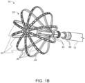
- Figure 1B is a partly exploded view of an example distal end assembly of a non-limiting example of a catheter-based electrophysiology device, in the non-limiting example of Figure 1B , a configuration called a basket catheter.
- FIG. 1B The non-limiting example shown in Figure 1B is a distal end assembly of a catheter, for operation within a patient's body.
- an end assembly 10 of a catheter 12 has a basket shape with a plurality of splines 24.
- a spline 24 may optionally include one or more electrodes 26 and/or one or more sensors 26.
- the electrodes 26 and/or sensors 26 may be mounted on a flexible PCB included in the spline 24.
- ends 42 (only some of which are labeled, for the sake of simplicity) of the splines 24 are optionally provided with electrical connection to wires (not shown) passing through lumens 66 in the catheter 12.
- manufacturing a catheter which has plurality of conductors passing through lumens along a length of the catheter by threading the wires through the lumens requires a significant amount of manual labor.
- Manufacturing and assembly of the conductors in the catheter is potentially simplified by using a flexible PCB upon which are arranged a required number of conductive traces.
- multiple wires threaded through multiple lumens in a catheter may not provide the flexibility needed for negotiating bending angles which a catheter may need to negotiate.
- embodiments are described which are suitable, by way of some non-limiting examples, for electrically connecting sensors for operation within a heart, through a catheter, to instruments outside a patient's body.
- An aspect of some embodiments includes replacing the wires (not shown) passing through lumens 66 in the catheter 12, with an elongate flexible PCB including multiple conductive traces serving for signal conductance along the catheter.
- FIG. 2A is a simplified block diagram illustration of a PCB cable assembly for connecting a distal end assembly to a proximal end connector according to an example embodiment.
- Figure 2A is intended to illustrate a concept of an example elongate flexible PCB 234, within a catheter 240.
- the elongate flexible PCB 234 has a distal end connector 236, with electrical connection(s) for connecting to a distal assembly 238, by way of a non-limiting example, to a catheter-based electrophysiology device, optionally the non-limiting example of Figure 1B , a configuration called a basket catheter sensor.
- the elongate flexible PCB 234 has a proximal end connector 232, with electrical connection(s) for connecting to, by way of a non-limiting example, medical instruments to use signal
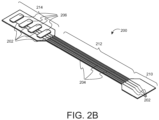
- FIG. 2B is a simplified illustration of a PCB cable assembly according to an example embodiment.
- Figure 2B shows an elongate flexible PCB 200, having multiple conductive traces 202 laid along a length of the elongate flexible PCB 200, and multiple slits 204 cutting through the elongate flexible PCB 200 parallel to and between the conductive traces 202.
- Figure 2B shows three sections of the elongate flexible PCB 200 - a proximal end section 210, a mid-section 212, and a distal end section 214.
- the end section 210 may be located at a proximal end section of a catheter, the mid-section 212 may pass through a shaft of the catheter, and the end section 214 may be located at a distal end section of the catheter.
- the end section 210 may be located at a distal end section of a catheter, the mid-section 212 may pass through a shaft of the catheter, and the end section 214 may be located at a proximal end section of the catheter.
- the mid-section 212 extends 75%, 80%, 85%, 90% 95% or even up to 98%, or 99% of a length of the elongate flexible PCB 200, yet not reach either end of the elongate flexible PCB.
- the proximal end 210 and the distal end 214 of the elongate flexible PCB 200 are not cut through, and the remaining material connects the separated-by-the-slits strips, making them potentially easier to handle as a group of strips.
- the elongate flexible PCB 200 is sized to be packaged within a catheter.
- a length of the elongate flexible PCB 200 is designed to extend a full length of a catheter (not shown) into which the elongate flexible PCB 200 is planned to be inserted.
- a length of the elongate flexible PCB 200 is designed to extend more than a full length of a catheter (not shown) into which the elongate flexible PCB 200 is planned to be inserted, so the some of the proximal end section 210 and/or the distal end section 214 may jut out of the catheter.
- proximal end section 210 is at an end of a catheter designed to be the end remaining outside of a patient's body.
- the conductive traces 202 are optionally electrically connected to electric components 206 such as electrodes 206 or sensors 206.
- Figure 2B shows the electric components at the distal end section 214. However, such electric components may be attached to the conductive traces 202 at the proximal end section 210.
- the conductive traces 202 are optionally electrically connected to electric connection pads (not shown), for connecting to additional circuitry.
- Figure 2B shows the electric components 206 at the distal end section 214, so electric connection pads may be at the proximal end section 210. However, such electric connection pads may also optionally be at the distal end section 214.
- a width of the elongate flexible PCB 200 is designed to be less than a diameter of a catheter (not shown) into which the elongate flexible PCB 200 is planned to be inserted.
- a width of the elongate flexible PCB 200 is designed to be less than a circumference of a catheter (not shown) into which the elongate flexible PCB 200 is planned to be inserted, and the elongate flexible PCB 200 is inserted with the catheter and lies along the circumference of the catheter against an inner surface of the catheter.
- the elongate flexible PCB 200 is designed to be twisted and/or rolled. When twisted or rolled, an outer diameter of the elongate flexible PCB 200 is less than a width of the elongate flexible PCB 200, and can be inserted into a catheter diameter smaller than the width of the elongate flexible PCB 200.
- Figure 3 is a simplified illustration of an elongate flexible PCB according to an example embodiment.
- Figure 3 is intended to show an embodiment where an elongate flexible PCB, forming a PCB cable assembly, includes slits and conductive traces similarly to slits 204 and conductive traces 202 shown in the mid-section 212 of Figure 2B .
- Figure 3 illustrates a configuration of an elongate flexible PCB 302, having multiple conductive traces 304 laid along a length of the elongate flexible PCB 302, and multiple slits 306 cutting through the elongate flexible PCB 302 parallel to and between the conductive traces 304, and electric contacts 308 at one end of the conductive traces 304, the left end in Figure 3 .
- the configuration shown in Figure 3 is a configuration where the slits 306 split the elongate flexible PCB 302 into multiple separate strips attached to each other at one end, the left end of Figure 3 . It is noted that a corresponding configuration, where the multiple separate strips are attached to each other at the other end, the right end of Figure 3 , is also contemplated.
- the elongate flexible PCB 302 may optionally include one or more of the slits 306 extending to both ends of the elongate flexible PCB 302 (not shown in Figure 3 ). In such a configuration (not shown in Figure 3 ) the slits 306 split the elongate flexible PCB 302 into multiple separate strips.
- Proximal and distal ends of the elongate flexible PCB s 302 312 322 may or may not include contact pads or sensors.
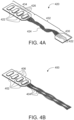
- FIG. 4A is a simplified illustration of a PCB cable assembly according to an example embodiment.
- Figure 4A shows an elongate flexible PCB forming a PCB cable assembly in which a group of traces are shown twisted.
- Such an elongate flexible PCB provides a group of twisted traces which can potentially remove cross talk between signals carried via the traces, and/or remove cross talk between signals carried by neighboring groups of twisted traces.
- the elongate flexible PCB may optionally include shielding of the traces to shield from electromagnetic (EM) interference between signals carried via the groups of traces.
- EM electromagnetic
- Figure 4A illustrates a configuration of an elongate flexible PCB 420, having multiple conductive traces 422 laid along a length of the elongate flexible PCB 420, and multiple slits cutting through the elongate flexible PCB 420 parallel to and between the conductive traces 422, and electric contacts 426 at one end of the conductive traces 422, the left end in Figure 4A .
- the configuration shown in Figure 4A is a configuration where the electric contacts 426 are shown at the left end of Figure 4A . It is noted that a corresponding configuration, where the electric contacts 426 are at the other end, the right end of Figure 4A , is also contemplated. In some embodiments the electrical contacts 426 may be present at both ends of the conductive traces 422.
- Figure 4A shows a non-limiting example of a specific number of strips 424 of twisted flexible PCB with traces.
- a different number of twisted strips 424 may be used, for example 2, 3, 5, 6, 7, 8, 9, 10 strips twisted together, and even more.
- a number of flexible PCB strips 420 may be twisted around each other, for example 2, 3, 4, 5, 6, 7, 8, 9, 10 flexible PCB strips, and even more, may be twisted around each other.
- Figure 4B is a simplified illustration of an elongate flexible PCB according to an example embodiment.
- Figure 4B shows an elongate flexible PCB forming a PCB cable assembly, in which one or more pair(s) of traces are shown twisted.
- Such an elongate flexible PCB provides twisted traces which can potentially remove cross talk between signals carried via the traces.
- the elongate flexible PCB may optionally include shielding of the traces to shield from electromagnetic (EM) interference between signals carried via the traces.
- EM electromagnetic
- Figure 4B illustrates a configuration of an elongate flexible PCB 400, having multiple conductive traces 402 laid along a length of the elongate flexible PCB 400, and multiple slits cutting through the elongate flexible PCB 400 parallel to and between the conductive traces 402, and electric contacts 406 at one end of the conductive traces 402, the left end in Figure 4B .
- FIG. 4B The configuration shown in Figure 4B is a configuration where the slits split the elongate flexible PCB 400 into multiple separate strips attached to each other at one end, the left end of Figure 4B . It is noted that a corresponding configuration, where the multiple separate strips are attached to each other at the other end, the right end of Figure 4B , is also contemplated.
- the multiple separate strips may optionally be twisted around each other.
- Figure 4B shows a non-limiting example of two pairs 404 of twisted flexible PCB with traces.
- a different number of twisted pairs 404 may be used, for example 1, 2, 3, 4, 5, 6, 7, 8, 9, 10 twisted pairs, and even more.
- a different number of flexible PCB strips may be twisted around each other, for example 2, 3, 4, 5, 6, 7, 8, 9, 10 strips with traces, and even more, may be twisted around each other.
- different combinations of different numbers of twisted strips may be combined in one flexible PCB.
- a twisted pair and a twisted triplet, or a twisted quadruplet, and other similar combinations may be combined in one flexible PCB.
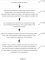
- Figure 5 is a simplified flow chart illustration of a method of connecting a distal end assembly of a catheter to a connector at a proximal end of the catheter, according to an example embodiment.
- the method exemplified in Figure 5 includes:
- elongate flexible PCB includes a plurality of electrical connection pads at ends of the conductive traces.
- At least some of the conductive traces are twisted about each other before the inserting the conductive cable into the catheter.
- Example 1 The catheter according to Example 1 wherein the plurality of slits (204, 306) extends along more than 75% of the elongate flexible PCB.
- the catheter according to any one of Examples 1-6 including a plurality of elongate flexible PCBs being housed within the shaft of the catheter.
- a method of connecting a distal end assembly of a catheter to a connector at a proximal end of the catheter including providing a catheter shaft (502), providing an elongate flexible PCB (Printed Circuit Board) sized to extend an entire length of the catheter shaft, having a plurality of parallel conductive traces laid along a length of the elongate flexible PCB (504), cutting elongate slits through the elongate flexible PCB between and parallel to at least some of the conductive traces (506), inserting the elongate flexible PCB into the catheter shaft such that the elongate flexible PCB extends at least a full length of the shaft of the catheter (508), and connecting the electrical connection pads on a distal end of the elongate flexible PCB to a distal end assembly and the electrical connection pads on a proximal end of the elongate flexible PCB to a connector configured to connect to a controller (510), wherein the controller is configured to communicate electrical signals between the controller and the distal end assembly.
- Example 8 The method according to Example 8 wherein the elongate flexible PCB includes a plurality of electrical connection pads at ends of the conductive traces
- a group of conductors including a plurality of elongate flexible strips, each strip including a flexible PCB (200, 302, 400, 420), the flexible PCB including a PCB distal portion (214, 434) including a plurality of electrical connection pads (206, 406, 426) configured for establishing electrical connection with an electrical connection array of a distal sensing assembly, a PCB proximal portion (210, 430) including a plurality of conductive traces (202, 304, 402, 422) corresponding to the plurality of electric connection pads (206, 406, 426) of the PCB distal portion, wherein the plurality of conductive traces is configured to be electrically connectable to an external electric connector, a PCB median portion (212, 432) including a plurality of conductive traces (202, 304, 402, 422) laid longitudinally along more than 75% of a length of the elongate flexible PCB, the conductive traces continuing the conductive traces of the PCB proximal portion and electrically connected to the pluralit
- Example 16 The group according to Example 16 wherein the conductive traces are insulated from each other.
- Example 20 The group according to Example 20 wherein the group extends from a proximal end to a distal end of the catheter.
- example is used herein to mean “serving as an example, instance or illustration”. Any embodiment described as an “example” is not necessarily to be construed as preferred or advantageous over other embodiments and/or to exclude the incorporation of features from other embodiments.
Landscapes
- Health & Medical Sciences (AREA)
- Life Sciences & Earth Sciences (AREA)
- Engineering & Computer Science (AREA)
- Surgery (AREA)
- General Health & Medical Sciences (AREA)
- Veterinary Medicine (AREA)
- Public Health (AREA)
- Animal Behavior & Ethology (AREA)
- Physics & Mathematics (AREA)
- Molecular Biology (AREA)
- Biomedical Technology (AREA)
- Heart & Thoracic Surgery (AREA)
- Medical Informatics (AREA)
- Cardiology (AREA)
- Otolaryngology (AREA)
- Nuclear Medicine, Radiotherapy & Molecular Imaging (AREA)
- Plasma & Fusion (AREA)
- Microelectronics & Electronic Packaging (AREA)
- Biophysics (AREA)
- Pathology (AREA)
- Measurement And Recording Of Electrical Phenomena And Electrical Characteristics Of The Living Body (AREA)
- Coupling Device And Connection With Printed Circuit (AREA)
Applications Claiming Priority (2)
| Application Number | Priority Date | Filing Date | Title |
|---|---|---|---|
| US202363541306P | 2023-09-29 | 2023-09-29 | |
| US18/822,984 US20250107844A1 (en) | 2023-09-29 | 2024-09-03 | Pcb cable assembly for a catheter |
Publications (1)
| Publication Number | Publication Date |
|---|---|
| EP4555922A1 true EP4555922A1 (de) | 2025-05-21 |
Family
ID=92925932
Family Applications (1)
| Application Number | Title | Priority Date | Filing Date |
|---|---|---|---|
| EP24203089.8A Pending EP4555922A1 (de) | 2023-09-29 | 2024-09-27 | Pcb-kabelanordnung für einen katheter |
Country Status (5)
| Country | Link |
|---|---|
| US (1) | US20250107844A1 (de) |
| EP (1) | EP4555922A1 (de) |
| CN (1) | CN119732731A (de) |
| CR (1) | CR20240403A (de) |
| IL (1) | IL315926A (de) |
Citations (19)
| Publication number | Priority date | Publication date | Assignee | Title |
|---|---|---|---|---|
| JPS6440119U (de) * | 1987-09-04 | 1989-03-09 | ||
| JPH02271843A (ja) * | 1989-04-13 | 1990-11-06 | Olympus Optical Co Ltd | 電子走査型超音波プローブ |
| JPH0513408U (ja) * | 1991-08-06 | 1993-02-23 | 横河メデイカルシステム株式会社 | 内視鏡型超音波プローブ |
| US5391199A (en) | 1993-07-20 | 1995-02-21 | Biosense, Inc. | Apparatus and method for treating cardiac arrhythmias |
| US5558091A (en) | 1993-10-06 | 1996-09-24 | Biosense, Inc. | Magnetic determination of position and orientation |
| US6172499B1 (en) | 1999-10-29 | 2001-01-09 | Ascension Technology Corporation | Eddy current error-reduced AC magnetic position measurement system |
| US6239724B1 (en) | 1997-12-30 | 2001-05-29 | Remon Medical Technologies, Ltd. | System and method for telemetrically providing intrabody spatial position |
| US6332089B1 (en) | 1996-02-15 | 2001-12-18 | Biosense, Inc. | Medical procedures and apparatus using intrabody probes |
| US20020062082A1 (en) * | 2000-11-21 | 2002-05-23 | Asahi Kogaku Kogyo Kabushiki Kaisha | Ultrasonic endoscope |
| US6484118B1 (en) | 2000-07-20 | 2002-11-19 | Biosense, Inc. | Electromagnetic position single axis system |
| US6618612B1 (en) | 1996-02-15 | 2003-09-09 | Biosense, Inc. | Independently positionable transducers for location system |
| US6690963B2 (en) | 1995-01-24 | 2004-02-10 | Biosense, Inc. | System for determining the location and orientation of an invasive medical instrument |
| US6892091B1 (en) | 2000-02-18 | 2005-05-10 | Biosense, Inc. | Catheter, method and apparatus for generating an electrical map of a chamber of the heart |
| US20060058676A1 (en) * | 2002-04-17 | 2006-03-16 | Tomoyuki Yagi | Ultrasonic probe in body cavity |
| US7536218B2 (en) | 2005-07-15 | 2009-05-19 | Biosense Webster, Inc. | Hybrid magnetic-based and impedance-based position sensing |
| US7756576B2 (en) | 2005-08-26 | 2010-07-13 | Biosense Webster, Inc. | Position sensing and detection of skin impedance |
| US7848787B2 (en) | 2005-07-08 | 2010-12-07 | Biosense Webster, Inc. | Relative impedance measurement |
| US7869865B2 (en) | 2005-01-07 | 2011-01-11 | Biosense Webster, Inc. | Current-based position sensing |
| US8456182B2 (en) | 2008-09-30 | 2013-06-04 | Biosense Webster, Inc. | Current localization tracker |
-
2024
- 2024-09-03 US US18/822,984 patent/US20250107844A1/en active Pending
- 2024-09-25 IL IL315926A patent/IL315926A/en unknown
- 2024-09-26 CR CR20240403A patent/CR20240403A/es unknown
- 2024-09-27 EP EP24203089.8A patent/EP4555922A1/de active Pending
- 2024-09-27 CN CN202411359019.5A patent/CN119732731A/zh active Pending
Patent Citations (21)
| Publication number | Priority date | Publication date | Assignee | Title |
|---|---|---|---|---|
| JPS6440119U (de) * | 1987-09-04 | 1989-03-09 | ||
| JPH02271843A (ja) * | 1989-04-13 | 1990-11-06 | Olympus Optical Co Ltd | 電子走査型超音波プローブ |
| JPH0513408U (ja) * | 1991-08-06 | 1993-02-23 | 横河メデイカルシステム株式会社 | 内視鏡型超音波プローブ |
| US5391199A (en) | 1993-07-20 | 1995-02-21 | Biosense, Inc. | Apparatus and method for treating cardiac arrhythmias |
| US5443489A (en) | 1993-07-20 | 1995-08-22 | Biosense, Inc. | Apparatus and method for ablation |
| US5558091A (en) | 1993-10-06 | 1996-09-24 | Biosense, Inc. | Magnetic determination of position and orientation |
| US6690963B2 (en) | 1995-01-24 | 2004-02-10 | Biosense, Inc. | System for determining the location and orientation of an invasive medical instrument |
| US6618612B1 (en) | 1996-02-15 | 2003-09-09 | Biosense, Inc. | Independently positionable transducers for location system |
| US6332089B1 (en) | 1996-02-15 | 2001-12-18 | Biosense, Inc. | Medical procedures and apparatus using intrabody probes |
| US6788967B2 (en) | 1997-05-14 | 2004-09-07 | Biosense, Inc. | Medical diagnosis, treatment and imaging systems |
| US6239724B1 (en) | 1997-12-30 | 2001-05-29 | Remon Medical Technologies, Ltd. | System and method for telemetrically providing intrabody spatial position |
| US6172499B1 (en) | 1999-10-29 | 2001-01-09 | Ascension Technology Corporation | Eddy current error-reduced AC magnetic position measurement system |
| US6892091B1 (en) | 2000-02-18 | 2005-05-10 | Biosense, Inc. | Catheter, method and apparatus for generating an electrical map of a chamber of the heart |
| US6484118B1 (en) | 2000-07-20 | 2002-11-19 | Biosense, Inc. | Electromagnetic position single axis system |
| US20020062082A1 (en) * | 2000-11-21 | 2002-05-23 | Asahi Kogaku Kogyo Kabushiki Kaisha | Ultrasonic endoscope |
| US20060058676A1 (en) * | 2002-04-17 | 2006-03-16 | Tomoyuki Yagi | Ultrasonic probe in body cavity |
| US7869865B2 (en) | 2005-01-07 | 2011-01-11 | Biosense Webster, Inc. | Current-based position sensing |
| US7848787B2 (en) | 2005-07-08 | 2010-12-07 | Biosense Webster, Inc. | Relative impedance measurement |
| US7536218B2 (en) | 2005-07-15 | 2009-05-19 | Biosense Webster, Inc. | Hybrid magnetic-based and impedance-based position sensing |
| US7756576B2 (en) | 2005-08-26 | 2010-07-13 | Biosense Webster, Inc. | Position sensing and detection of skin impedance |
| US8456182B2 (en) | 2008-09-30 | 2013-06-04 | Biosense Webster, Inc. | Current localization tracker |
Also Published As
| Publication number | Publication date |
|---|---|
| IL315926A (en) | 2025-04-01 |
| US20250107844A1 (en) | 2025-04-03 |
| CN119732731A (zh) | 2025-04-01 |
| CR20240403A (es) | 2025-01-06 |
Similar Documents
| Publication | Publication Date | Title |
|---|---|---|
| US12156694B2 (en) | Electroporation systems and catheters for electroporation systems | |
| EP3797689B1 (de) | Darstellung von intrakardialem elektrokardiogramm | |
| EP3790484B1 (de) | Spitzenelektrodenanordnungen für intravaskulären katheter | |
| US20220000537A1 (en) | Devices and Methods for Electrosurgical Navigation | |
| EP2797648B1 (de) | Elektrisch transparente einführschleuse | |
| US20090177111A1 (en) | System and method for displaying contact between a catheter and tissue | |
| EP3958774B1 (de) | Elektrodendesign mit reduzierter impedanz | |
| US10973436B2 (en) | Pericardiocentesis needle guided by cardiac electrophysiology mapping | |
| AU2018237071A1 (en) | Sensing system for pericardial access | |
| US20180325586A1 (en) | Single catheter for cardiac ablation and mapping | |
| JP2024119902A (ja) | 電気解剖学的マッピングシステム | |
| EP3363355B1 (de) | Elektrophysiologische vorrichtung und verfahren zur konstruktion der elektrophysiologischen vorrichtung | |
| EP4585146A1 (de) | Impedanzbasierte verfolgung der katheterposition in bezug auf eine hohlraumwand | |
| US20250009278A1 (en) | Electroanatomical mapping device with internal electrode | |
| US20250107844A1 (en) | Pcb cable assembly for a catheter | |
| US20240407730A1 (en) | Electroanatomical mapping enable dilator and sheath with electrical coupling | |
| US20260013932A1 (en) | Expandable catheter with a coil-spring assembly | |
| EP4393426A2 (de) | Multielektrodenkatheter mit verschachteltem substrat |
Legal Events
| Date | Code | Title | Description |
|---|---|---|---|
| PUAI | Public reference made under article 153(3) epc to a published international application that has entered the european phase |
Free format text: ORIGINAL CODE: 0009012 |
|
| STAA | Information on the status of an ep patent application or granted ep patent |
Free format text: STATUS: THE APPLICATION HAS BEEN PUBLISHED |
|
| AK | Designated contracting states |
Kind code of ref document: A1 Designated state(s): AL AT BE BG CH CY CZ DE DK EE ES FI FR GB GR HR HU IE IS IT LI LT LU LV MC ME MK MT NL NO PL PT RO RS SE SI SK SM TR |
|
| STAA | Information on the status of an ep patent application or granted ep patent |
Free format text: STATUS: REQUEST FOR EXAMINATION WAS MADE |
|
| 17P | Request for examination filed |
Effective date: 20250819 |