EP4555978A1 - Stabilisateur distal - Google Patents
Stabilisateur distal Download PDFInfo
- Publication number
- EP4555978A1 EP4555978A1 EP23839657.6A EP23839657A EP4555978A1 EP 4555978 A1 EP4555978 A1 EP 4555978A1 EP 23839657 A EP23839657 A EP 23839657A EP 4555978 A1 EP4555978 A1 EP 4555978A1
- Authority
- EP
- European Patent Office
- Prior art keywords
- catheter
- mesh portion
- distal
- biological lumen
- proximal side
- Prior art date
- Legal status (The legal status is an assumption and is not a legal conclusion. Google has not performed a legal analysis and makes no representation as to the accuracy of the status listed.)
- Pending
Links
Images


Classifications
-
- A—HUMAN NECESSITIES
- A61—MEDICAL OR VETERINARY SCIENCE; HYGIENE
- A61M—DEVICES FOR INTRODUCING MEDIA INTO, OR ONTO, THE BODY; DEVICES FOR TRANSDUCING BODY MEDIA OR FOR TAKING MEDIA FROM THE BODY; DEVICES FOR PRODUCING OR ENDING SLEEP OR STUPOR
- A61M25/00—Catheters; Hollow probes
- A61M25/01—Introducing, guiding, advancing, emplacing or holding catheters
- A61M25/06—Body-piercing guide needles or the like
- A61M25/0662—Guide tubes
-
- A—HUMAN NECESSITIES
- A61—MEDICAL OR VETERINARY SCIENCE; HYGIENE
- A61B—DIAGNOSIS; SURGERY; IDENTIFICATION
- A61B17/00—Surgical instruments, devices or methods
- A61B17/22—Implements for squeezing-off ulcers or the like on inner organs of the body; Implements for scraping-out cavities of body organs, e.g. bones; for invasive removal or destruction of calculus using mechanical vibrations; for removing obstructions in blood vessels, not otherwise provided for
- A61B2017/22079—Implements for squeezing-off ulcers or the like on inner organs of the body; Implements for scraping-out cavities of body organs, e.g. bones; for invasive removal or destruction of calculus using mechanical vibrations; for removing obstructions in blood vessels, not otherwise provided for with suction of debris
-
- A—HUMAN NECESSITIES
- A61—MEDICAL OR VETERINARY SCIENCE; HYGIENE
- A61F—FILTERS IMPLANTABLE INTO BLOOD VESSELS; PROSTHESES; DEVICES PROVIDING PATENCY TO, OR PREVENTING COLLAPSING OF, TUBULAR STRUCTURES OF THE BODY, e.g. STENTS; ORTHOPAEDIC, NURSING OR CONTRACEPTIVE DEVICES; FOMENTATION; TREATMENT OR PROTECTION OF EYES OR EARS; BANDAGES, DRESSINGS OR ABSORBENT PADS; FIRST-AID KITS
- A61F2/00—Filters implantable into blood vessels; Prostheses, i.e. artificial substitutes or replacements for parts of the body; Appliances for connecting them with the body; Devices providing patency to, or preventing collapsing of, tubular structures of the body, e.g. stents
- A61F2/82—Devices providing patency to, or preventing collapsing of, tubular structures of the body, e.g. stents
- A61F2/86—Stents in a form characterised by the wire-like elements; Stents in the form characterised by a net-like or mesh-like structure
- A61F2/90—Stents in a form characterised by the wire-like elements; Stents in the form characterised by a net-like or mesh-like structure characterised by a net-like or mesh-like structure
-
- A—HUMAN NECESSITIES
- A61—MEDICAL OR VETERINARY SCIENCE; HYGIENE
- A61F—FILTERS IMPLANTABLE INTO BLOOD VESSELS; PROSTHESES; DEVICES PROVIDING PATENCY TO, OR PREVENTING COLLAPSING OF, TUBULAR STRUCTURES OF THE BODY, e.g. STENTS; ORTHOPAEDIC, NURSING OR CONTRACEPTIVE DEVICES; FOMENTATION; TREATMENT OR PROTECTION OF EYES OR EARS; BANDAGES, DRESSINGS OR ABSORBENT PADS; FIRST-AID KITS
- A61F2/00—Filters implantable into blood vessels; Prostheses, i.e. artificial substitutes or replacements for parts of the body; Appliances for connecting them with the body; Devices providing patency to, or preventing collapsing of, tubular structures of the body, e.g. stents
- A61F2/95—Instruments specially adapted for placement or removal of stents or stent-grafts
- A61F2/962—Instruments specially adapted for placement or removal of stents or stent-grafts having an outer sleeve
- A61F2/966—Instruments specially adapted for placement or removal of stents or stent-grafts having an outer sleeve with relative longitudinal movement between outer sleeve and prosthesis, e.g. using a push rod
-
- A—HUMAN NECESSITIES
- A61—MEDICAL OR VETERINARY SCIENCE; HYGIENE
- A61M—DEVICES FOR INTRODUCING MEDIA INTO, OR ONTO, THE BODY; DEVICES FOR TRANSDUCING BODY MEDIA OR FOR TAKING MEDIA FROM THE BODY; DEVICES FOR PRODUCING OR ENDING SLEEP OR STUPOR
- A61M25/00—Catheters; Hollow probes
- A61M25/01—Introducing, guiding, advancing, emplacing or holding catheters
- A61M2025/0175—Introducing, guiding, advancing, emplacing or holding catheters having telescopic features, interengaging nestable members movable in relations to one another
-
- A—HUMAN NECESSITIES
- A61—MEDICAL OR VETERINARY SCIENCE; HYGIENE
- A61M—DEVICES FOR INTRODUCING MEDIA INTO, OR ONTO, THE BODY; DEVICES FOR TRANSDUCING BODY MEDIA OR FOR TAKING MEDIA FROM THE BODY; DEVICES FOR PRODUCING OR ENDING SLEEP OR STUPOR
- A61M25/00—Catheters; Hollow probes
- A61M25/01—Introducing, guiding, advancing, emplacing or holding catheters
- A61M25/06—Body-piercing guide needles or the like
- A61M25/0662—Guide tubes
- A61M2025/0681—Systems with catheter and outer tubing, e.g. sheath, sleeve or guide tube
-
- A—HUMAN NECESSITIES
- A61—MEDICAL OR VETERINARY SCIENCE; HYGIENE
- A61M—DEVICES FOR INTRODUCING MEDIA INTO, OR ONTO, THE BODY; DEVICES FOR TRANSDUCING BODY MEDIA OR FOR TAKING MEDIA FROM THE BODY; DEVICES FOR PRODUCING OR ENDING SLEEP OR STUPOR
- A61M25/00—Catheters; Hollow probes
- A61M25/01—Introducing, guiding, advancing, emplacing or holding catheters
- A61M25/09—Guide wires
- A61M2025/09125—Device for locking a guide wire in a fixed position with respect to the catheter or the human body
-
- A—HUMAN NECESSITIES
- A61—MEDICAL OR VETERINARY SCIENCE; HYGIENE
- A61M—DEVICES FOR INTRODUCING MEDIA INTO, OR ONTO, THE BODY; DEVICES FOR TRANSDUCING BODY MEDIA OR FOR TAKING MEDIA FROM THE BODY; DEVICES FOR PRODUCING OR ENDING SLEEP OR STUPOR
- A61M25/00—Catheters; Hollow probes
- A61M25/01—Introducing, guiding, advancing, emplacing or holding catheters
- A61M25/09—Guide wires
- A61M2025/09133—Guide wires having specific material compositions or coatings; Materials with specific mechanical behaviours, e.g. stiffness, strength to transmit torque
- A61M2025/09141—Guide wires having specific material compositions or coatings; Materials with specific mechanical behaviours, e.g. stiffness, strength to transmit torque made of shape memory alloys which take a particular shape at a certain temperature
-
- A—HUMAN NECESSITIES
- A61—MEDICAL OR VETERINARY SCIENCE; HYGIENE
- A61M—DEVICES FOR INTRODUCING MEDIA INTO, OR ONTO, THE BODY; DEVICES FOR TRANSDUCING BODY MEDIA OR FOR TAKING MEDIA FROM THE BODY; DEVICES FOR PRODUCING OR ENDING SLEEP OR STUPOR
- A61M25/00—Catheters; Hollow probes
- A61M25/01—Introducing, guiding, advancing, emplacing or holding catheters
- A61M25/02—Holding devices, e.g. on the body
- A61M25/04—Holding devices, e.g. on the body in the body, e.g. expansible
Definitions
- the present invention relates to a distal stabilizer for use in a catheter delivery in a biological lumen.
- Patent Document 1 discloses an anchoring device in which a cylindrical portion (locking stent) is joined to the distal end of a delivery wire.
- Patent Document 1 US Patent No. 968221
- the treatment catheter that is slidably fitted over the microcatheter has a large outer diameter and high rigidity. Therefore, the treatment catheter repeatedly applies a force to pull the microcatheter or the delivery wire having low rigidity to the proximal side during the advancement.
- a blood vessel which is a biological lumen
- the treatment catheter is easily caught on a bent portion or a bifurcated portion, and when a force is applied to make the treatment catheter to pass through the bent portion or the bifurcated portion, a force for pulling the microcatheter or the delivery wire to the proximal side is applied repeatedly.
- the application of the force to pull the delivery wire to the proximal side may cause a displacement of the cylindrical portion locked to the inner wall in the biological lumen.
- the cylindrical portion is displaced, it is necessary to store the cylindrical portion in the microcatheter, release the cylindrical portion from the distal side of the microcatheter in the vicinity of the target position, and lock the cylindrical portion in the biological lumen. Therefore, it takes time and effort to deliver the treatment catheter to the vicinity of the target location.
- An object of the present invention is to provide a distal stabilizer capable of suppressing displacement of a cylindrical portion locked in a biological lumen.
- the present invention is directed to a distal stabilizer for use in catheter delivery in a biological lumen, the distal stabilizer including: a linear delivery member; and a cylindrical portion that extends from a distal end of the linear delivery member and is locked to an inner wall of the biological lumen by a mesh pattern structure, in which the cylindrical portion has a range of an effective length, and includes an easily deformable portion on a proximal side of the range of the effective length, such that the proximal side is more deformable than a distal side of the effective length.
- An opening area of each cell constituting the mesh pattern structure of the easily deformable portion may be larger than an opening area of each cell constituting the mesh pattern structure of the distal side of the cylindrical portion.
- An opening area of each cell constituting the mesh pattern structure of the easily deformable portion may be larger than a reference opening area.
- a ratio of a length of the easily deformable portion in an axial direction relative to the range of the effective length of the cylindrical portion may be 1:0.5 to 1:0.2.
- a distal stabilizer capable of suppressing displacement of a cylindrical portion locked in a biological lumen.
- the long axis direction in a state where the distal stabilizer 1 extends linearly is also referred to as an "axial direction LD" or simply as an “axial direction”.
- axial direction LD the proximal side close to the practitioner is referred to as “D1”, and the distal side away from the practitioner is referred to as "D2".
- FIG. 1 shows a delivery system 10 including a distal stabilizer 1 according to an embodiment.
- FIG. 2 is a perspective view showing a state in which a main body portion 11 of a locking stent 2 is virtually expanded in a plane.
- the delivery system 10 shown in FIG. 1 is a system used to deliver a treatment device (described below) in a biological lumen.
- the blood vessels of the biological lumen in which the delivery system 10 is used are not particularly limited, but typically include tortuous large cerebral blood vessels and the like.
- the delivery system 10 includes the distal stabilizer 1 and a plurality of catheters, including a first catheter 5 and a second catheter 6.
- the distal stabilizer 1 is a device used for catheter delivery in a biological lumen.
- the distal stabilizer 1 includes the locking stent (cylindrical portion) 2 and a delivery wire (linear delivery member) 3.
- each "cell” described later refers to a portion surrounded by portions made of a wire-shaped material forming a mesh pattern structure.
- Each "strut” refers to an elongated rod-shaped or band-shaped portion made of the wire-shaped material.
- the locking stent 2 is an anchoring device that extends from a distal end 3f of the delivery wire 3 and is lockable to the inner wall of the biological lumen by a self-expanding force.
- the locking stent 2 is housed in the first catheter 5 in a state reduced in diameter, and is locked to the inner wall of the biological lumen by being released from the first catheter 5 and deployed in the biological lumen.
- the biological lumen is not particularly limited, and may be a blood vessel (an artery or a vein) of the brain, a coronary artery, an upper or lower limb, or the like, an organ, or the like.
- the locking stent 2 includes a main body portion 11 and an antenna portion 12.
- the main body portion 11 is a portion configured to have a cylindrical shape in a state expanded in diameter, and has a mesh pattern structure described later. As shown in FIG. 2 , the range of the main body portion 11 in the axial direction LD corresponds to the range of the effective length VL of the locking stent 2.
- the range of the effective length VL refers to a range between distal end portions 16f of cells 16 (described later) located on the most distal side D2 of the mesh pattern structure and a proximal end portion 17n of the cell 17 (described later) located on the most proximal side D1.
- the locking stent 2 of the present embodiment there are a plurality of cells 16 located on the most distal side D2 of the mesh pattern structure and a plurality of cells 17 located on the most proximal side D1.
- the number of cells located on the most distal side and the most proximal side may be one, respectively.
- the locking stent 2 can support the inner wall of the biological lumen by increasing the diameter in the main body portion 11 (the range of the effective length VL).
- the mesh pattern structure of the main body portion 11 is simplified.
- the antenna portion 12 is a portion at which a portion on the proximal side of the main body portion 11 converges to the distal end 3f of the delivery wire 3.
- the antenna portion 12 has a mesh pattern structure and is designed so as not to support the inner wall of the biological lumen when expanded at the inner diameter of the blood vessel at the target position.
- the locking stent 2 includes, at its distal and proximal ends, markers (not shown), each made of X-ray opaque material. Each of the markers of the locking stent 2 is a mark for confirming the position of the distal end and the proximal end of the locking stent 2 in the X-ray transmission image.
- the locking stent 2 can be made, for example, by performing laser processing on a tube made of a biocompatible material, particularly preferably a superelastic alloy. In a case of producing the locking stent 2 from a superelastic alloy tube, in order to reduce the cost, it is preferable to produce the locking stent 2 by performing laser processing on a tube of about 2 to 3 mm, then expanding the tube to a desired diameter, and subjecting the tube to shape memory treatment.
- the locking stent 2 is not limited to laser processing, and may be produced by cutting or the like, or may be produced by braiding a wire-shaped metal wire into a tubular shape. In a case in which the material or thickness of the strut is changed depending on the region of the locking stent 2 in the axial direction, if the material is metallic, two mesh portions to be described later may be joined by welding or the like.
- the locking stent 2 is preferably made of a material having high rigidity and high biocompatibility.
- a material having high rigidity and high biocompatibility examples include titanium, nickel, stainless steel, platinum, gold, silver, copper, iron, chromium, cobalt, aluminum, molybdenum, manganese, tantalum, tungsten, niobium, magnesium, calcium, and alloys containing these.
- a synthetic resin material of a polyolefin such as polyethylene (PE) or polypropylene (PP), polyamide, polyvinyl chloride, polyphenylene sulfide, polycarbonate, polyether, polymethyl methacrylate or the like may be used.
- biodegradable resin such as polylactic acid (PLA), polyhydroxybutyrate (PHB), polyglycolic acid (PGA), or poly ⁇ -caprolactone may be used.
- PLA polylactic acid
- PHB polyhydroxybutyrate
- PGA polyglycolic acid
- poly ⁇ -caprolactone poly ⁇ -caprolactone
- titanium, nickel, stainless steel, platinum, gold, silver, copper, magnesium, and alloys containing these are preferable.
- the alloy include a Ni-Ti alloy, a Cu-Mn alloy, a Cu-Cd alloy, a Co-Cr alloy, a Cu-Al-Mn alloy, an Au-Cd-Ag alloy, and a Ti-Al-V alloy.
- examples of the alloy include an alloy of magnesium and Zr, Y, Ti, Ta, Nd, Nb, Zn, Ca, Al, Li, Mn, or the like.
- a Ni-Ti alloy is preferable.
- a plurality of cells (cells 16 and 17 to be described later) defined by a plurality of struts arranged in a frame shape are spread in the radial direction (circumferential direction) RD.
- a part of the plurality of cells spread in the radial direction RD is continuously arranged along the axial direction LD. That is, the main body portion 11 has a mesh pattern structure in which a plurality of cells are spread in the radial direction RD and a part of the cells is continuously arranged along the axial direction LD.
- the circumferential direction refers to an outer circumferential direction of the main body portion 11.
- the radial direction RD (a direction orthogonal to the axial direction LD) shown in FIG. 2 corresponds to the circumferential direction in the main body portion 11 virtually expanded in a plane.
- the mesh pattern structure includes a first mesh portion 13 and a second mesh portion (an easily deformable portion) 14.
- the first mesh portion 13 and the second mesh portion 14 are regions having different ease of deformation in the main body portion 11.
- the second mesh portion 14, which is more easily deformed than the first mesh portion 13 is adjacent to the first mesh portion 13 in the axial direction.
- the first mesh portion 13 and the second mesh portion 14 partially overlap each other in the circumferential direction, but may be a configuration not overlapping.
- an intermediate position between the first mesh portion 13 and the second mesh portion 14 may be defined as a boundary between the first mesh portion 13 and the second mesh portion 14 in the axial direction LD.
- the boundary between the first mesh portion 13 and the second mesh portion 14 has a zigzag pattern shape along the circumferential direction.
- its boundary can be specified by the same method.
- the first mesh portion 13 is a portion of the main body portion 11 located on the distal side D2 in the axial direction LD.
- the first mesh portion 13 has a self-expanding force, and expands by being released from the catheter to support the inner wall of the blood vessel. Even when the delivery wire 3 is pulled toward the proximal side D1, the first mesh portion 13 is in a state of supporting the inner wall of the blood vessel. Therefore, the first mesh portion 13 expands to support the inner wall of the blood vessel, such that the blood flow is secured and the locking stent 2 can be anchored to the inner wall of the blood vessel. As shown in FIG. 2 , the first mesh portion 13 includes the plurality of cells 16. In FIG.
- the first mesh portion 13 is provided between a proximal end portion 16n of the cell 16 located on the most proximal side D1 in the axial direction LD and the distal end portions 16f of the cells 16 located on the most distal side D2.
- each of the cells 16 constituting the first mesh portion 13 has substantially the same shape, and therefore has substantially the same opening area.
- the opening area of each of the cells 16 is, for example, about 1 to 10 mm 2 .
- a value obtained by arithmetic mean from the opening areas of all of the cells 16 constituting the first mesh portion 13 can be used.
- the cell pattern of the cells 16 constituting the first mesh portion 13 is not particularly limited, but may be all open cells or all closed cells. As a cell pattern of the cell 16, closed cells and open cells may coexist. It should be noted that, in the present disclosure, the definitions of an open cell and a closed cell are not uniquely defined. For example, in a closed cell including a free end, a half region surrounded by two sides (struts) forming the free end may be defined as an open cell, and the other half region may be defined as a closed cell, or alternatively, a closed cell including a free end may be defined as an open cell, and a closed cell not including a free end may be defined as a closed cell.
- the second mesh portion 14 is a portion located more to the proximal side D1 of the main body portion 11 than the first mesh portion 13.
- the second mesh portion 14 has a self-expanding force and expands by being released from the catheter to support the inner wall of the blood vessel.
- the second mesh portion 14 no longer supports the inner wall of the blood vessel.
- the second mesh portion 14 includes the plurality of cells 17.
- the second mesh portion 14 is provided between the proximal end portion 17n of the cell 17 located on the most proximal side D1 in the axial direction LD and distal end portions 17f of the cells 17 located on the most distal side D2.
- the second mesh portion 14 of the present embodiment includes three cells 17, but the number of cells may be four or more or less than three.
- the shapes of the cells 17 constituting the second mesh portion 14 may be different from one another or may be the same.
- the cell pattern of the cells 17 constituting the second mesh portion 14 is not particularly limited, but may be all open cells or all closed cells. As a pattern of the cell 17, closed cells and open cells may coexist.
- the second mesh portion 14 is provided as an easily deformable portion that is more easily deformed than the first mesh portion 13. Specifically, the second mesh portion 14 extends more easily in the axial direction than the first mesh portion 13 and has a lower bending rigidity in the axial direction.
- the elongation ratio of each of the first mesh portion 13 and the second mesh portion 14 can be calculated as a ratio to the original sample length, for example, by forming each portion to have a predetermined sample length, loading the portions into a small diameter tube, and measuring the length in the axial direction.
- the diameter of the small diameter tube used in the test may be, for example, the smallest diameter of the blood vessel in which the distal stabilizer 1 is used.
- the elongation ratio of the second mesh portion 14 is preferably, for example, about 150 to 300% of the elongation ratio of the first mesh portion 13.
- the bending rigidity in the axial direction of each of the first mesh portion 13 and the second mesh portion 14 can be measured by forming each portion to have a predetermined sample length and performing, for example, a three-point bending test, a four-point bending test, or the like.
- the bending rigidity of the second mesh portion 14 is preferably about 30% to 70% of the bending rigidity of the first mesh portion 13.
- the bending rigidity of the second mesh portion 14 is preferably about 3 to 14 Nmm 2 .
- the second mesh portion 14 can be formed by, for example, entirely forming the first mesh portion 13 as the main body portion 11 and removing a portion of the struts in the region on the proximal side D1.
- the second mesh portion 14 is provided so that the opening area of each of the cells 17 constituting the second mesh portion 14 is larger than the opening area of each of the cells 16 constituting the first mesh portion 13 such that the second mesh portion 14 easily extends in the axial direction more than the first mesh portion 13 and the bending rigidity in the axial direction is lower than the first mesh portion 13.
- the opening area of each of the cells 17 is, for example, about 6 to 60 mm 2 .
- a value obtained by arithmetic mean from the opening areas of all of the cells 17 constituting the second mesh portion 14 can be used.
- the opening area of each of the cells 17 of the second mesh portion 14 may be larger than the reference opening area.
- the reference opening area is an opening area serving as a reference when determining the magnitude of the bending rigidity in the axial direction in the mesh pattern structure.
- the reference opening area is selected according to the degree of flexibility imparted to the second mesh portion 14.
- the ratio of the length of the second mesh portion 14 (the easily deformable portion) in the axial direction to the main body portion 11 is preferably 1:0.5 to 1:0.2 (the main body portion: the second mesh portion).
- the ratio of the length of the second mesh portion 14 in the axial direction to the main body portion 11 is less than 1:0.5 (lower limit value), it becomes difficult for the main body portion 11 to secure a locking force necessary for locking the locking stent 2 to the inner wall of the biological lumen.
- the ratio of the length of the second mesh portion 14 in the axial direction to the main body portion 11 exceeds 1:0.2 (the upper limit value)
- the characteristics of the second mesh portion 14 elongation and bending in the axial direction described later
- the delivery wire 3 is pulled toward the proximal side are impaired. Therefore, by setting the ratio of the length of the second mesh portion 14 in the axial direction to the main body portion 11 to 1:0.5 to 1:0.2, it is possible to sufficiently exhibit the characteristics of the second mesh portion 14, while securing the locking force of the first mesh portion 13.
- the delivery wire 3 is a member used when the locking stent 2 is advanced or retracted in the biological lumen.
- the delivery wire 3 is delivered toward the distal side D2 when the locking stent 2 is advanced within the biological lumen V, and is drawn toward the proximal side D1 when the locking stent 2 is retracted within the biological lumen V.
- the delivery wire 3 is made of, for example, a metal material having a high elastic modulus such as stainless steel.
- the diameter of the delivery wire 3 is not particularly limited as long as it has physical properties sufficient to perform an advancing or retracting operation in the biological lumen V and is adapted to the first catheter 5, and may be, for example, 0.005 to 0.018 inches.
- the linear delivery member is not limited to a metal material such as a delivery wire, and may be made of, for example, a resin or a composite material of a metal and a resin.
- the first catheter 5 is slidably fitted over the delivery wire 3.
- the first catheter 5 is, for example, a microcatheter.
- the second catheter 6 (described later) is slidably fitted over the first catheter 5.
- the diameter of the first catheter 5 is set according to a target position TP, and the inner diameter and the degree of bending of a biological lumen V of the path to the target position TP, and is not particularly limited, but the inner diameter is preferably 0.017 inches or less, and more preferably 0.0165 inches or less.
- one or more other catheters (not shown) slidably fitted over the second catheter 6 may be used as necessary. In general, by using a large number of catheters, a catheter having a large inner diameter can be ultimately inserted into the biological lumen V and advanced.
- a catheter having an inner diameter larger than that of the first catheter 5 is referred to as a treatment catheter.
- the treatment catheter is a catheter having an inner diameter sufficient to place the treatment device thereinside in an inserted manner or having an inner diameter sufficient to use itself as a treatment device.
- the treatment catheter may also be referred to as a guiding catheter in applications that place the treatment device thereinside in an inserted manner.
- the treatment device examples include a thrombus aspiration device, a flow diverter, an aneurysm embolization device, a thrombectomy device (such as a stent retriever), a stent for treating aneurysm, a stent for treating intracranial arterial stenosis, a balloon catheter, a shunt, and a liquid embolic substance release means (such as a catheter having a lumen through which a liquid embolic substance passes).
- the treatment catheter may itself be used as a treatment device. In such applications, the treatment catheter may also be referred to as a thrombus aspiration catheter.
- a case where the second catheter 6 is a treatment catheter will be described as an example.
- the biological lumen V is a blood vessel.
- the distal stabilizer 1 and the delivery system 10 of the present embodiment are suitably used when a highly bent tortuous blood vessel is included in a blood vessel.
- the distal stabilizer 1 and the delivery system 10 of the present embodiment are preferably used when the target position TP is located in a region having a blood vessel inner diameter of 7 mm or less, specifically, less than 2.5 mm (preferably, 2.0 mm or less or 1.5 mm or less).
- the target position TP may be a region after M2 (M2, M3, M4, etc.) of the middle cerebral artery (MCA), A1 and A2 regions of the anterior cerebral artery (ACA), a region after P1 (P1, P2, etc.) of the posterior cerebral artery (PCA), the internal carotid artery (ICA), etc.
- M2 M2, M3, M4, etc.
- ACA anterior cerebral artery
- P1 P1, P2, etc.
- ICA internal carotid artery
- the target position TP is not limited thereto, and may be located in a wide range of a blood vessel inner diameter of 0.5 to 10 mm.
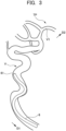
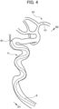
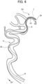
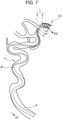
- FIGS. 3 to 11 are schematic diagrams each illustrating an example of a procedure performed by the delivery system 10 including the distal stabilizer 1.
- FIG. 12 is an enlarged view showing the shape of the locking stent 2 (2A) locked in the biological lumen V. Since the shape of the locking stent in a state of being locked in the biological lumen V and not being pulled toward the proximal side D1 is substantially the same in both the locking stent of the embodiment and the locking stent of the comparative example, the locking stent 2 of the embodiment is representatively illustrated in FIG. 12 .
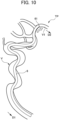
- the mesh pattern structure of the locking stent 2A of the comparative example includes cells having the same shape as a whole. In the locking stent 2A of the comparative example shown in FIG. 13 , the mesh pattern structure is the same as that of the first mesh portion 13, and will be described as a "mesh portion 15".
- FIG. 13 is an enlarged view showing a shape of the locking stent 2A of the comparative example when a force for pulling the first catheter 5 and the delivery wire 3 toward the proximal side D1 is applied.
- the locking stent 2A of the comparative example shown in FIG. 13 is a stent of a conventional example configured by cells having the same shape.
- FIG. 14 is an enlarged view showing the shape of the locking stent 2 of the embodiment when a force is applied to pull the first catheter 5 and the delivery wire 3 to the proximal side D1.
- the central axis line L0 of each of the locking stents (2, 2A) indicates an imaginary central axis line in the axial direction of the locking stent locked in the biological lumen V.
- the second catheter 6 is disposed on the proximal side D1 of the biological lumen V of a patient.
- a distal end 61 of the second catheter 6 is caught by the bending portion or the branching portion of the biological lumen V, and it is difficult to advance the second catheter 6 further to the distal side.
- the first catheter 5 is inserted into the second catheter 6 to be delivered into the biological lumen V and pushed out of the distal end 61 of the second catheter 6, and then a distal end 51 of the first catheter 5 is disposed in the vicinity of the target position TP. Subsequently, as shown in FIG.
- the distal stabilizer 1 is inserted into the first catheter 5 and placed in the vicinity of the target position TP. At this time, the locking stent 2 of the distal stabilizer 1 is housed in the first catheter 5 in a state reduced in diameter.
- the distal stabilizer 1 (the locking stent 2 and the delivery wire 3) is housed over the entire area of the first catheter 5, but for convenience, the distal stabilizer 1 is illustrated by a broken line only on the distal side of the first catheter 5.
- the locking stent 2 housed in the first catheter 5 in the state reduced in diameter is released from the distal end 51 of the first catheter 5. Release of the locking stent 2 is performed by an operation of retracting the first catheter 5 toward the proximal side D1.
- the locking stent 2 released from the distal end 51 of the first catheter 5 expands in diameter due to its self-expanding force. As a result, the locking stent 2 pushes the inner wall V1 of the biological lumen V from the inside toward the outside, and is locked to the inner wall V1.
- the second catheter is slidably fitted over the first catheter 5, and the second catheter 6 is advanced to the distal side D2 in the biological lumen V.
- the second catheter 6 has a large outer diameter and high rigidity. Therefore, the second catheter 6 repeatedly applies a force to pull the first catheter 5 or the delivery wire 3 having low rigidity toward the proximal side D1 in the process of advancing.
- the position of the locking stent locked to the inner wall in the biological lumen V may be displaced due to the application of the force for pulling the delivery wire toward the proximal side D1.
- both the first mesh portion 13 and the second mesh portion 14 support the inner wall V1.
- the inner wall V1 is supported over the entire region in the axial direction.
- force F a force that pulls the delivery wire 3 toward the proximal side D1
- the range R1 on the proximal side of the mesh portion 15 on which the force F acts becomes close to the central axis line L0.
- a direction D0 is also referred to as a "pulling-out direction D0" or a "direction to pull out D0".
- the range R1 on the proximal side of the mesh portion 15 is close to the central axis line L0, much of the force F acts in the direction D0 in which the locking stent 2A is pulled out toward the proximal side in the biological lumen V. Therefore, when the delivery wire 3 is pulled toward the proximal side, positional displacement of the locking stent 2A is likely to occur.
- the second mesh portion 14 having an elongation ratio in the axial direction higher than that of the first mesh portion 13 extends toward the proximal side D1 together with the antenna portion 12, such that the force for pulling the delivery wire 3 toward the proximal side D1 is relaxed by the elongation of the second mesh portion 14, and the force hardly propagates to the first mesh portion 13.
- the locking stent 2 of the present embodiment shown in FIG. 14 shows that when the force F for pulling the delivery wire 3 toward the proximal side D1 is applied, as shown in FIG. 14 , the second mesh portion 14 having an elongation ratio in the axial direction higher than that of the first mesh portion 13 extends toward the proximal side D1 together with the antenna portion 12, such that the force for pulling the delivery wire 3 toward the proximal side D1 is relaxed by the elongation of the second mesh portion 14, and the force hardly propagates to the first mesh portion 13.
- the range R2 on the proximal side of the second mesh portion 14 on which the force F acts is away from the central axis line L0 of the locking stent 2.
- the force acting in the direction D0 in which the locking stent 2 is pulled out to the proximal side in the biological lumen V becomes smaller than that in FIG. 13 due to the dispersion of the force F. Therefore, it is possible to more effectively suppress the displacement of the locking stent 2 when the delivery wire 3 is pulled toward the proximal side.
- an operation of pulling the delivery wire 3 toward the proximal side D1 may be performed in a state where the locking stent 2 is locked to the inner wall V1 of the biological lumen V.
- the second catheter 6 can be advanced toward the distal side D2. Specifically, when the delivery wire 3 is pulled toward the proximal side D1 in a state in which the locking stent 2 is locked to the inner wall V1, the path of the delivery wire 3 in the biological lumen V becomes close to a straight line and becomes short.
- the position of the portion of the proximal side D1 of the second catheter 6 does not change, and instead, as shown in FIG. 9 , the distal end 61 of the second catheter 6 advances in the biological lumen V. Further, when the distal end 61 of the second catheter 6 advances into the biological lumen V without changing the position of the portion of the second catheter 6 on the proximal side D1, the path of the second catheter 6 becomes close to a straight line. This operation is particularly beneficial when the second catheter 6 attempts to pass through a place where it is difficult to pass through, for example, a place where the bending of the biological lumen V is severe or a place where the inner diameter is small. According to the distal stabilizer 1 of the present embodiment, even when such an operation is performed, it is possible to suppress displacement of the locking stent 2 locked to the inner wall V1 of the biological lumen V.
- the first catheter 5 inserted into the treatment catheter (the second catheter 6) in the middle of advancement may stray and enter the aneurysm together with the delivery wire 3.
- the path of the delivery wire 3 in the biological lumen V is shortened, and thus the delivery wire 3 and the first catheter 5 can be returned into the biological lumen V from the aneurysm.
- the distal stabilizer 1 of the present embodiment since it is possible for the distal stabilizer 1 of the present embodiment to suppress the displacement of the locking stent 2 locked in the biological lumen V, even when the operation of returning the wire or the catheter which has strayed and entered the aneurysm to the inside of the biological lumen V is performed, it is possible for the distal stabilizer 1 to be suitably used for the application of delivering the treatment catheter to the vicinity of the target position in a state where the locking stent 2 is locked to the distal side of the aneurysm.
- the distal stabilizer 1 is retracted toward the proximal side D1 and housed in the first catheter 5 (not shown). After the distal stabilizer 1 is housed in the first catheter 5, the first catheter 5 and the distal stabilizer 1 may be removed from the proximal side D1 of the second catheter 6. Alternatively, after the first catheter 5 is removed from the proximal side D1, the distal stabilizer 1 may be housed in the second catheter 6 and removed from the proximal side D1.
- the distal stabilizer 1 of the present embodiment since the flexibility of the second mesh portion 14 on the proximal side is high, it is possible for the distal stabilizer 1 to be easily housed (resheathed) in the first catheter 5 or the second catheter 6.
- the second catheter 6 by providing the second catheter 6 at the target position TP in the biological lumen V, it is possible to easily deliver a treatment device 7 inserted into the second catheter 6 to the target position TP.
- the second catheter 6 or the third catheter itself may be used as a treatment device.
- the thrombus at the target position TP is aspirated and removed from the distal end 61 by applying a negative pressure to the internal flow path of the second catheter 6.
- the removal of the distal stabilizer 1 is not limited to removal before the delivery of the treatment device 7, but may be removal after the delivery of the treatment device 7.
- the second catheter 6 has at least a double structure of a lumen through which the distal stabilizer 1 and the first catheter 5 are inserted and a lumen through which the treatment device 7 is inserted.
- the treatment device 7 is, for example, a thrombus aspiration device, a flow diverter, an aneurysm embolization device, a thrombectomy device (such as a stent retriever), an aneurysm treatment stent, an intracranial arterial stenosis treatment stent, a balloon catheter, a shunt, or a liquid embolic substance release means (such as a catheter with a lumen through which the liquid embolic substance passes).
- these treatment devices can also be delivered, in terms of transcatheter, to the above-described region of the vessel inner diameter of 0.5 mm to 10 mm, preferably 7 mm or less, specifically less than 2.5 mm (preferably 2.0 mm or less, or 1.5 mm or less), and diseases or conditions (vascular occlusions, aneurysms, etc.) in these regions can be treated or ameliorated with little burden on the patient.
- diseases or conditions vascular occlusions, aneurysms, etc.
- the treatment device 7 delivered to the target position TP may be used in the biological lumen (a thrombus aspiration device, a flow diverter, an aneurysm embolization device, a thrombectomy device, a stent for treating aneurysm, a stent for treating intracranial arterial stenosis, a balloon catheter, or a means for releasing liquid embolic substance, etc.) or may be used by protruding out of the biological lumen (a shunt or the like).
- the distal stabilizer 1 of the present embodiment is also applied to a method of delivering the treatment device 7 to the target position TP in the biological lumen V by the delivery system 10 for performing a therapeutic action at the target position TP in the biological lumen V, or for causing the treatment device 7 to protrude from the target position TP in the biological lumen V to the outside of the biological lumen V to perform a therapeutic action.
- the distal stabilizer 1 of the present embodiment has, on the proximal side of the locking stent 2, the second mesh portion (the easily deformable portion) 14 that is more deformable than the distal side of the locking stent 2.
- the second mesh portion 14 having an elongation ratio higher than that of the first mesh portion 13 extends to the proximal side, and therefore, the force for pulling the delivery wire 3 to the proximal side is relaxed by the elongation of the second mesh portion 14, and the force hardly propagates to the first mesh portion 13. Therefore, when the delivery wire 3 is pulled toward the proximal side, it is possible to suppress displacement of the locking stent locked to the inner wall in the biological lumen.
- the entire second mesh portion 14 having low bending rigidity in the axial direction deforms into a substantially conical shape together with the antenna portion 12 and is largely bent in the axial direction along the bending of the biological lumen V. Therefore, in the locking stent 2, the range R2 on the distal side of the second mesh portion 14 on which the force F acts is away from the central axis line L0 of the locking stent 2 (refer to FIG. 14 ).
- the locking stent 2 of the embodiment is more likely to deform on the proximal side in the axial direction than on the distal side, stress is less likely to concentrate on both end portions in the axial direction of the locking stent 2. According to this configuration, since the blood vessel to be locked is less likely to have a shape close to a straight line, the inner wall of the blood vessel is more protected.
- the second mesh portion 14 has flexibility by making the opening area of each of the cells 17 larger than that of each of the cells 16 of the first mesh portion 13. Therefore, it is possible to set the flexibility (bending rigidity) of the second mesh portion 14 within a desired range by appropriately adjusting the opening area of each of the cells 17 of the second mesh portion 14.
- the first mesh portion 13 can easily secure the locking force necessary for locking the locking stent 2 to the inner wall of the biological lumen. Further, by setting the ratio of the length of the first mesh portion 13 to the second mesh portion 14 to be less than 1:4, it is possible to prevent the characteristics (elongation or bending toward the proximal side) of the second mesh portion 14 from being impaired when the delivery wire 3 is pulled toward the proximal side.
- the following configuration may be applied.
Landscapes
- Health & Medical Sciences (AREA)
- Life Sciences & Earth Sciences (AREA)
- Biophysics (AREA)
- Pulmonology (AREA)
- Engineering & Computer Science (AREA)
- Anesthesiology (AREA)
- Biomedical Technology (AREA)
- Heart & Thoracic Surgery (AREA)
- Hematology (AREA)
- Animal Behavior & Ethology (AREA)
- General Health & Medical Sciences (AREA)
- Public Health (AREA)
- Veterinary Medicine (AREA)
- Media Introduction/Drainage Providing Device (AREA)
Applications Claiming Priority (2)
| Application Number | Priority Date | Filing Date | Title |
|---|---|---|---|
| JP2022113422 | 2022-07-14 | ||
| PCT/JP2023/025753 WO2024014485A1 (fr) | 2022-07-14 | 2023-07-12 | Stabilisateur distal |
Publications (2)
| Publication Number | Publication Date |
|---|---|
| EP4555978A1 true EP4555978A1 (fr) | 2025-05-21 |
| EP4555978A4 EP4555978A4 (fr) | 2025-11-26 |
Family
ID=89536792
Family Applications (1)
| Application Number | Title | Priority Date | Filing Date |
|---|---|---|---|
| EP23839657.6A Pending EP4555978A4 (fr) | 2022-07-14 | 2023-07-12 | Stabilisateur distal |
Country Status (4)
| Country | Link |
|---|---|
| US (1) | US20260007863A1 (fr) |
| EP (1) | EP4555978A4 (fr) |
| JP (1) | JP2024012161A (fr) |
| WO (1) | WO2024014485A1 (fr) |
Families Citing this family (1)
| Publication number | Priority date | Publication date | Assignee | Title |
|---|---|---|---|---|
| CN120381358A (zh) * | 2025-04-24 | 2025-07-29 | 艾柯医疗器械(北京)股份有限公司 | 一种支架输送装置及包含其的支架系统 |
Family Cites Families (6)
| Publication number | Priority date | Publication date | Assignee | Title |
|---|---|---|---|---|
| US968221A (en) | 1910-02-08 | 1910-08-23 | Wilcox & White Co | Tracker construction for mechanical music-playing instruments. |
| DE10233085B4 (de) * | 2002-07-19 | 2014-02-20 | Dendron Gmbh | Stent mit Führungsdraht |
| WO2010077973A2 (fr) * | 2008-12-17 | 2010-07-08 | Sanjay Shrivastava | Procédé et appareil de filtration d'une lumière corporelle |
| WO2013071173A1 (fr) * | 2011-11-11 | 2013-05-16 | Dacuycuy Nathan John | Dispositifs pour l'élimination des occlusions vasculaires |
| CN110090063B (zh) * | 2018-01-30 | 2022-07-08 | 上海沃比医疗科技有限公司 | 血栓捕捉装置及其方法 |
| KR102125615B1 (ko) * | 2018-08-28 | 2020-06-22 | 인제대학교 산학협력단 | 스텐트 시술장치 |
-
2023
- 2023-07-12 EP EP23839657.6A patent/EP4555978A4/fr active Pending
- 2023-07-12 US US18/992,144 patent/US20260007863A1/en active Pending
- 2023-07-12 JP JP2023114664A patent/JP2024012161A/ja active Pending
- 2023-07-12 WO PCT/JP2023/025753 patent/WO2024014485A1/fr not_active Ceased
Also Published As
| Publication number | Publication date |
|---|---|
| EP4555978A4 (fr) | 2025-11-26 |
| US20260007863A1 (en) | 2026-01-08 |
| WO2024014485A1 (fr) | 2024-01-18 |
| JP2024012161A (ja) | 2024-01-25 |
Similar Documents
| Publication | Publication Date | Title |
|---|---|---|
| JP5733759B2 (ja) | 方向性のある拡張をする脈管内器具 | |
| US8241345B2 (en) | Stent delivery system | |
| JP5793620B2 (ja) | ステント送達システム、およびステントを送達シテム内に拘束する方法 | |
| EP3755276A1 (fr) | Nouveau dispositif intra-sacculaire de type orb amélioré | |
| CA2429992A1 (fr) | Dispositifs d'endoprothese a bobines distales ou proximales amovibles | |
| US8709063B2 (en) | Bifurcated stent introducer system | |
| JP2004358242A (ja) | 改善された放射線不透過性腔内医療装置 | |
| JP2016073553A (ja) | プッシャーガイドワイヤ | |
| EP4555978A1 (fr) | Stabilisateur distal | |
| EP3025684A1 (fr) | Stent auto-extensible | |
| US20210298774A1 (en) | Wire-equipped stent, catheter, and catheter-stent system | |
| JP2024042127A (ja) | 生体管腔中でのカテーテルデリバリに用いる遠位スタビライザ、治療デバイスのデリバリシステム、及び治療デバイス | |
| WO2022004850A1 (fr) | Stabilisateur distal pour pose d'un cathéter à l'intérieur d'une lumière biologique, système de placement de dispositif de traitement, et dispositif de traitement | |
| US20070142900A1 (en) | Stent including a portal and methods of use thereof | |
| CN110251285B (zh) | 渐缩型血管支架 | |
| US20220233821A1 (en) | Distal stabilizer for use for catheter delivery in biological lumen, delivery system for delivering treatment device, and treatment device | |
| EP4582128A1 (fr) | Stabilisateur distal | |
| EP4582129A1 (fr) | Stabilisateur distal | |
| US20260124432A1 (en) | Distal stabilizer | |
| US20260041447A1 (en) | Distal stabilizer | |
| WO2024241863A1 (fr) | Stabilisateur distal et procédé d'imagerie pour stabilisateur distal | |
| JP3754055B2 (ja) | 体腔内狭窄部治療用器具 | |
| EP4473996A1 (fr) | Stabilisateur distal et son procédé d'imagerie | |
| WO2024195733A1 (fr) | Stabilisateur distal | |
| EP2907457A1 (fr) | Composant pour implantation dans un organisme vivant, endoprothèse, composant d'embolisation, kit d'expansion de vaisseau sanguin, et kit d'embolisation d'anévrisme |
Legal Events
| Date | Code | Title | Description |
|---|---|---|---|
| STAA | Information on the status of an ep patent application or granted ep patent |
Free format text: STATUS: THE INTERNATIONAL PUBLICATION HAS BEEN MADE |
|
| PUAI | Public reference made under article 153(3) epc to a published international application that has entered the european phase |
Free format text: ORIGINAL CODE: 0009012 |
|
| STAA | Information on the status of an ep patent application or granted ep patent |
Free format text: STATUS: REQUEST FOR EXAMINATION WAS MADE |
|
| 17P | Request for examination filed |
Effective date: 20250213 |
|
| AK | Designated contracting states |
Kind code of ref document: A1 Designated state(s): AL AT BE BG CH CY CZ DE DK EE ES FI FR GB GR HR HU IE IS IT LI LT LU LV MC ME MK MT NL NO PL PT RO RS SE SI SK SM TR |
|
| REG | Reference to a national code |
Ref country code: DE Ref legal event code: R079 Free format text: PREVIOUS MAIN CLASS: A61F0002900000 Ipc: A61M0025000000 |
|
| DAV | Request for validation of the european patent (deleted) | ||
| DAX | Request for extension of the european patent (deleted) | ||
| A4 | Supplementary search report drawn up and despatched |
Effective date: 20251024 |
|
| RIC1 | Information provided on ipc code assigned before grant |
Ipc: A61M 25/00 20060101AFI20251020BHEP Ipc: A61M 25/01 20060101ALI20251020BHEP Ipc: A61M 25/06 20060101ALI20251020BHEP Ipc: A61M 25/04 20060101ALI20251020BHEP Ipc: A61M 25/09 20060101ALI20251020BHEP Ipc: A61F 2/90 20130101ALI20251020BHEP Ipc: A61B 17/22 20060101ALI20251020BHEP Ipc: A61F 2/01 20060101ALI20251020BHEP Ipc: A61F 2/844 20130101ALI20251020BHEP Ipc: A61F 2/966 20130101ALI20251020BHEP |