EP4556080A2 - Installation d'extinction d'eau et procédé de commande d'un cycle d'essai de pompe dans une installation d'extinction d'eau - Google Patents
Installation d'extinction d'eau et procédé de commande d'un cycle d'essai de pompe dans une installation d'extinction d'eau Download PDFInfo
- Publication number
- EP4556080A2 EP4556080A2 EP25161899.7A EP25161899A EP4556080A2 EP 4556080 A2 EP4556080 A2 EP 4556080A2 EP 25161899 A EP25161899 A EP 25161899A EP 4556080 A2 EP4556080 A2 EP 4556080A2
- Authority
- EP
- European Patent Office
- Prior art keywords
- pump
- fluid
- extinguishing
- test run
- line
- Prior art date
- Legal status (The legal status is an assumption and is not a legal conclusion. Google has not performed a legal analysis and makes no representation as to the accuracy of the status listed.)
- Pending
Links
Images


Classifications
-
- A—HUMAN NECESSITIES
- A62—LIFE-SAVING; FIRE-FIGHTING
- A62C—FIRE-FIGHTING
- A62C37/00—Control of fire-fighting equipment
- A62C37/50—Testing or indicating devices for determining the state of readiness of the equipment
-
- A—HUMAN NECESSITIES
- A62—LIFE-SAVING; FIRE-FIGHTING
- A62C—FIRE-FIGHTING
- A62C35/00—Permanently-installed equipment
- A62C35/58—Pipe-line systems
-
- A—HUMAN NECESSITIES
- A62—LIFE-SAVING; FIRE-FIGHTING
- A62C—FIRE-FIGHTING
- A62C35/00—Permanently-installed equipment
- A62C35/58—Pipe-line systems
- A62C35/68—Details, e.g. of pipes or valve systems
-
- G—PHYSICS
- G08—SIGNALLING
- G08B—SIGNALLING SYSTEMS, e.g. PERSONAL CALLING SYSTEMS; ORDER TELEGRAPHS; ALARM SYSTEMS
- G08B29/00—Checking or monitoring of signalling or alarm systems; Prevention or correction of operating errors, e.g. preventing unauthorised operation
- G08B29/02—Monitoring continuously signalling or alarm systems
- G08B29/04—Monitoring of the detection circuits
- G08B29/043—Monitoring of the detection circuits of fire detection circuits
Definitions
- the present invention relates to a control device and a method for controlling a pump test run, in particular in a water extinguishing system.
- Water extinguishing systems within the meaning of the invention are in particular sprinkler, spray water and foam extinguishing systems, whereby the invention is not limited to particular types of water extinguishing systems.
- the present invention particularly relates to water extinguishing systems comprising a fluid supply for providing an extinguishing fluid, a pump configured to convey the extinguishing fluid from the fluid supply into a supply line of a pipe system of the water extinguishing system, and a sampling line branching off from the supply line of the pipe system and configured to direct the extinguishing fluid conveyed by the pump away from the pipe system.
- the sampling line has an opening member configured to be movable between a blocking position, in which the opening member closes the sampling line, and an unlocking position, in which the opening member opens the sampling line.
- the water extinguishing system further comprises a fluid diversion having a reduced cross-section compared to the sampling line, wherein the fluid diversion is configured to direct a predefined portion of the extinguishing fluid around the opening member away from the pipe system.
- the fluid supply is understood to be a combination of one or more elements that serve to supply the water extinguishing system with extinguishing fluid.
- the fluid supply may, in particular, comprise a drinking water supply from which drinking water can be supplied to the water extinguishing system as extinguishing fluid.
- the fluid supply may comprise a storage tank in which the extinguishing fluid can be stored.
- a test line is typically understood to be a water measuring device comprising a flow meter, settling sections, and regulating valves for testing the water flow.
- the test line is preferably provided as a branch from the supply line to the pipe system of the water extinguishing system, in particular as a branch from the distribution pipe downstream of the pump, which serves to supply the pipe system.
- a distribution pipe specifically describes a pipe that either directly feeds a branch pipe or a single sprinkler on a branch pipe that does not have a tailpipe and is over 300 mm long. The pipes that serve to supply the pipe system thus form the supply line to the pipe system.
- the test line is used to carry out a so-called pump test run, in which the functionality of the pump of the water extinguishing system can be tested.
- the test line comprises an opening element.
- An opening element is understood in particular to be a sliding element within an opening unit, such as a valve, which can be operated manually according to the prior art. Opening is achieved by moving the sliding element from a blocked to an unlocked position.
- the opening element in the test line is opened. This enables a volume flow through the test line, by means of which a pump test run can be carried out. Closing then occurs by moving the sliding element from the unlocked position to the blocked position. This interrupts the volume flow through the valve.
- the test line is therefore the line that is used for the pump test run in the case of a manually carried out pump test run in order to form a test circuit.
- the test line is opened for the duration of the pump test run, and on the other hand, the supply of extinguishing fluid to the pipe system is prevented. This ensures that the extinguishing fluid is guided within the test circuit created by the test line during the test run.
- the extinguishing fluid is led away from the pump through the test line and then either into a corresponding The extinguishing fluid reservoir and/or a drain are then directed. This means that no extinguishing fluid is introduced into the pipe system. Only after the pump test run is the test line closed again and the fluid supply to the pipe system restored. After that, the extinguishing fluid can flow back into the pipe system.
- a fluid bypass is understood to be an additional line provided in addition to the test line, which can also branch off either from the supply line to the pipe system or from the test line.
- the fluid bypass is characterized in that it has a cross-section that is much smaller than that of the test line.
- the cross-section of the fluid bypass corresponds, for example, to only 2 to 10% of the cross-section of the test line, and in other embodiments even less.
- the cross-section of the fluid bypass is selected such that it conducts in particular 2% of the pump's flow rate.
- the fluid bypass is also referred to as an emergency line.
- the fluid bypass is designed such that it directs the extinguishing fluid pumped by the pump away from the pipe system even when the opening element in the test line is in the blocked position. The fluid bypass therefore serves to direct the extinguishing fluid away from the pipe system around the opening element.
- extinguishing fluid therefore refers to a fluid used to extinguish and/or fight fires.
- This extinguishing fluid can, in particular, be extinguishing water, provided with or without additives.
- the extinguishing fluid can contain a foam, an antifreeze agent, or similar.
- the additives should, if possible, be selected to be optimal for the specific application of the water extinguishing system.
- the extinguishing fluid can also be pure extinguishing water. Other extinguishing fluids are also conceivable.
- VdS 2212 Water extinguishing systems of the aforementioned type are subject, among other things, to the regulations described in VdS 2212.
- paragraph 1.3.4 of VdS 2212 stipulates weekly inspections of the water extinguishing system by the system operator.
- the weekly tests include a check of the pump start-up of the pump used to deliver the extinguishing fluid. This requires a so-called pump test run, which must last until the pump's normal operating parameters are reached.
- test line is usually used in such water extinguishing systems, which enables a pump test and prevents the extinguishing fluid
- the areas monitored by the water extinguishing system are flooded weekly.
- This test line can be opened using the opening device for the purpose of the pump test run and closed again after the pump test run is completed. This makes it possible to provide a kind of "test circuit" for the duration of the pump test run, thus avoiding flooding of the monitored areas.
- the test line is configured to direct the extinguishing fluid flowing through it back into a storage tank and/or an intermediate tank configured as part of the fluid supply system. This allows the extinguishing fluid flowing through the test line during the pump test run to continue to be used by the water extinguishing system.
- the extinguishing fluid flowing through the test line is also directed into a wastewater tank and/or discharged via a wastewater line, rather than being stored.
- the fluid diversion can also be configured to direct the extinguishing fluid flowing through it back into the storage tank and/or an intermediate tank. Alternatively, the fluid diversion can also be configured to direct the extinguishing fluid flowing through it into a wastewater tank and/or discharge it into a wastewater line and/or otherwise divert it from the piping system and not make it available to the fluid supply again.
- the weekly pump test run is carried out manually by a trained person.
- the test line is released by opening the opening device.
- a starting device is then used to trigger the pump to start. This start can be automatic or manual.
- the starting pressure which corresponds to the pressure at the time the pump starts up, is then measured and recorded, and the pump test run is continued until the normal operating parameters of the pump's drive motor are reached.
- the test line is closed again using the opening device, and no further extinguishing fluid can enter the test line.
- a water extinguishing system of the type mentioned above wherein the water extinguishing system comprises at least one control device configured to determine at least one parameter indicative of the cross-section of the fluid diversion and to control a pump test run of the pump based on the parameter.
- the present invention allows the pump test run to be automated. Thus, it is no longer possible to simply start the pump test run "automatically”; instead, the entire pump test run can be performed without manual intervention. This allows a pump test run to be performed without the need for trained personnel on-site.
- a maintenance technician can send a signal, for example via a remote connection, to the pump control unit, which ensures that the pump is started – as is already known from the prior art – for example, by a pressure drop at the pump inlet.
- the further process can then be automated, without the need for a trained person on site. This is because, according to the present invention, the extinguishing fluid delivered by the pump during the automatic pump test run is guided via the fluid diversion, and accordingly, no opening or closing of the opening device is necessary.
- the fluid diversion has a much smaller opening cross-section than the test line, usually at least 2%, only a very small portion of the extinguishing fluid is diverted away from the pipe system via the fluid diversion and would be available in the event of a fire. not available for firefighting. Since this is only a small portion, efficient firefighting can still be carried out.
- the present invention is therefore based on the finding that the small proportion of extinguishing fluid that can be passed through the fluid diversion is sufficient to prevent the pump from running dry (and, for example, overheating) during the pump test run.
- the fluid diversion line can actually carry sufficient extinguishing fluid. Due to the reduced cross-section compared to the test line, even small deposits in the fluid diversion line can prevent sufficient extinguishing fluid flow. Accordingly, the pump test run must be controlled based on whether the fluid diversion line can adequately divert the extinguishing fluid pumped by the pump during the pump test run away from the pipe system.
- a novel control device which determines a parameter indicative of the cross-section of the fluid bypass and controls the pump test run based on this parameter.
- the control can be designed based on the parameter in particular such that the parameter is used to determine - directly or indirectly - whether the cross-section of the fluid bypass is still large enough to supply sufficient extinguishing fluid to the pump. If this direct or indirect determination shows that sufficient extinguishing fluid can be supplied through the fluid bypass, the pump test run can be continued. If the determination shows that the extinguishing fluid flow is insufficient, the control device can be configured to abort the pump test run.
- control device can be understood as any type of device that is quantitatively capable of controlling the pump test run of the pump based on the question of whether the cross-section of the fluid diversion is suitable and sufficient to ensure a sufficient flow of extinguishing fluid during the pump test run and thus to prevent the pump from running dry.
- control device can be designed, in particular, as a combination of a sensor and a control unit.
- the control unit of the control device can be arranged, in particular, on or in the vicinity of the pump.
- control unit can be provided as a separate unit specifically designed to control the pump test run.
- control unit can also be implemented as an additional module of the control system for automatic pump start (by reducing the pressure).
- control unit for the pump test run according to the present invention can also be configured as part of a central device of the water extinguishing system and communicate bidirectionally with the pump via a communication unit.
- Particularly suitable sensors for the control system are those that allow the determination of a parameter that provides information about the flow rate of the extinguishing fluid through the fluid diversion per unit of time and thus about the cross-section of the fluid diversion.
- Such sensors can include, in particular, temperature sensors on the pump, especially at the pump outlet, since the temperature at the pump is indicative of the amount of extinguishing fluid that passes through the fluid diversion during the pump test run.
- a vibration sensor and/or a noise sensor can be installed on the pump to measure the pump's vibrations and/or noise output during operation. If cavitation/deposits occur in the fluid bypass, the pump's vibration and/or noise output will change. These changes, compared to the values recorded during operation without cavitation/deposits, are also detected by the vibration sensor and/or the noise sensor and can thus indicate a change in the pump's operating condition and indicate that the pump test run should be aborted.
- the sensors may also include pressure sensors that determine a pressure difference, for example, between a first and a second end of the fluid bypass, or temperature sensors that also measure a temperature and/or a temperature difference, for example, at the first and second ends of the fluid bypass and/or at the inlet and outlet of the pump.
- a measurement of the temperature and/or temperature difference within the fluid bypass can thus, for example, allow for the detection of possible freezing of the fluid bypass, and a measurement at the pump can allow for the detection of pump overheating.
- the sensors may also include ultrasonic sensors capable of detecting deposits within the fluid diversion and thus a reduction in the cross-section.
- the sensors may include flow sensors configured to determine the flow rate per unit time through the fluid diversion and/or the flow rate difference, for example, between a first end and the second end of the fluid diversion.
- the fluid bypass can be located directly on the fluid bypass and/or in the inlet or outlet lines of the fluid bypass and/or in the vicinity, on and/or inside the pump.
- the one or more sensors of the control device transmit the sensor data to the control unit of the control device, which enables the pump operation to be controlled.
- the control device can evaluate the sensor data and thus determine the parameter indicative of the cross-section of the fluid diversion. The control can then be carried out depending on this parameter.
- the evaluation may include determining whether the flow rate per unit of time/the cross-section of the fluid diversion is within a predefined value range. If this is the case, it can be assumed that the pump is being supplied with sufficient extinguishing fluid. If the flow rate per unit of time/the cross-section falls below a predefined limit, it can no longer be assumed that the pump can still deliver sufficient extinguishing fluid. In this case, the control device can output a signal that interrupts the pump test run and/or prevents it from starting at all. This can prevent the pump from running dry during the test run.
- control device can also be designed in the form of a switching device, in particular a flow switch, which switches at a certain flow rate (as a parameter indicative of the cross-section). If this flow rate is undershot, the switching device switches from an activated position to a deactivated position. In the deactivated position, the pump is deactivated.
- the switching device can preferably be in the energetically more favorable state in the They are in the deactivation position and are shifted to the less energetically favorable state by the set flow rate. This ensures that the pump operation is interrupted in the event of a power failure.
- the pump is not deactivated by the switch in the event of a fire.
- This can be achieved, for example, by wiring the pump in two ways, whereby in the event of a fire, another switching device, such as a pressure switch within the pipe system, switches to an activated position and keeps the pump activated, even if the switching device switches to the deactivated position for the pump test run.
- another switching device such as a pressure switch within the pipe system
- the fluid diversion is configured to branch off from the sampling line or from the supply line of the piping system.
- the fluid diversion is preferably configured to divert a portion of the extinguishing fluid away from the pipe system around the opening member of the test line.
- the fluid diversion branches off from the supply line to the pipe system for this purpose. This means that the fluid diversion branches off with its first end, for example, from the distributor pipe behind the pump and thus diverts the extinguishing fluid delivered by the pump during the pump test run away from the pipe system.
- the fluid diversion ends with its second end in a drain.
- the second end of the fluid diversion branches off back into the fluid supply. Further configurations are possible as long as they allow the extinguishing fluid delivered by the pump during the pump test run to be diverted away from the pipe system.
- the fluid diversion can also be designed such that its first end branches off from the test line—at a position upstream of the opening member—and its second end leads back into the test line—at a position downstream of the opening member.
- the extinguishing fluid guided through the fluid diversion is first guided through the test line, and the fluid diversion serves to guide the extinguishing fluid delivered during the pump test run around the (closed) opening member.
- the test line guides the extinguishing fluid downstream of the opening member, for example, back into the fluid supply and/or into a drain, such as a wastewater network and/or a wastewater tank.
- the second end of the fluid diversion can also not lead into the test line, but separately from it back into the fluid supply and/or the drain.
- controlling the pump test run may comprise comparing a parameter value with a predetermined limit value, wherein the control device may be configured to terminate the pump test run if the limit value is exceeded or not reached and/or not to start the pump test run.
- control device can in particular be configured to evaluate the parameter indicative of the cross-section and to carry out the control of the pump test run on the basis of this evaluation.
- the evaluation comprises in particular determining a limit value for the parameter.
- a limit value in particular a minimum value
- the control device is configured to abort a pump test run that is already in progress.
- the control device is configured not to start the pump test run at all.
- a limit value can also be specified for this, in particular a minimum pressure value that must be maintained to prevent damage to the pump. If this value is exceeded, the control device will also abort an ongoing pump test run or prevent the pump test run from starting at all, if this hasn't already happened.
- the limit value may include, in particular, a maximum value for the temperature of the extinguishing fluid that must not be exceeded. If the maximum value is exceeded, the control device then aborts an ongoing pump test run and/or prevents it from starting.
- the limit values to be used in the evaluation can be predetermined and in particular depend on the pump used and/or its pump type and/or the pump category. These specifications can be taken, for example, from manufacturer specifications. However, they can also be regularly recalculated for each pump.
- the limit values can be stored, in particular, in a memory unit of the control unit and/or the central device.
- control device may be configured to ensure an operational readiness state of the water extinguishing system in the event of a power failure during the pump test run.
- the operating state is the state in which the water extinguishing system is in operation, i.e., is being used to carry out a fire protection operation.
- the control device can be configured to ensure such an operational readiness state even in the event of a power failure, in particular a power outage.
- the control device can comprise an energy storage device, such as a battery, which allows the pump to be controlled even in the event of a power failure and thus, for example, to abort the pump test run to save energy in the event of a fire.
- this switching device can be configured such that it is in the deactivation position in the more energy-efficient state.
- the switching device will transition to the deactivation position, thus aborting the pump test run so that the pump is in a ready-to-operate state in the event of a fire.
- control device may be configured to ensure an operating state of the water extinguishing system in the event of a fire during the pump test run.
- An operating state is understood to be the state into which the water extinguishing system changes in the event of a fire, i.e. in which the water extinguishing system is triggered and carries out fire fighting.
- the pump When automating the pump test run, it must be ensured that in the event of a fire, the pump is not switched off after the pump test run has been completed, but continues to run in order to continue supplying the water extinguishing system with extinguishing fluid.
- the control device must be configured to switch off/deactivate of the pump after completion of the pump test run in the event of a fire.
- control device is preferably connected by signal to a detection device, such as an alarm valve or a non-return valve with a flow detector of the water extinguishing system, which is configured to detect a fire event. If this detection device detects a fire event, the control device receives a signal that the pump should continue running even after the pump test run has been completed. The control device then controls the pump in such a way that the pump run is not interrupted after the test run has been completed.
- a detection device such as an alarm valve or a non-return valve with a flow detector of the water extinguishing system, which is configured to detect a fire event. If this detection device detects a fire event, the control device receives a signal that the pump should continue running even after the pump test run has been completed. The control device then controls the pump in such a way that the pump run is not interrupted after the test run has been completed.
- the control device is designed as a switching arrangement, such provision of an operating state in the event of a fire can be achieved in particular by appropriately wiring the pump.
- the pump is switched by at least two switching arrangements, one switching arrangement being set up to activate and deactivate the pump for the pump test run and a second switching arrangement, which comprises, for example, an alarm switch and/or a pressure switch, being set up to activate the pump in the event of a fire. If a fire occurs during the pump test run, the first switching arrangement can deactivate the pump test run, but the second switching arrangement ensures that the pump remains activated and delivers the extinguishing fluid for the water extinguishing system to extinguish the fire.
- the water extinguishing system may further comprise an input device configured to receive an automated input that causes the pump to start a pump test run.
- the water extinguishing system can, in particular, comprise a pump with a control system configured for a so-called automatic pump start.
- This automatic pump start means that the pump test run can be started automatically, in particular by entering a corresponding command via an input device.
- the advantage of this design is that the pump test run can also be initiated remotely, eliminating the need for on-site maintenance personnel. This eliminates the need for maintenance personnel to travel and return for weekly tests—and the associated costs. Furthermore, more pump test runs can be performed, as a single person can conduct multiple test runs in parallel and collect the corresponding data.
- control device may comprise at least one flow sensor, wherein the parameter may indicate a flow rate of the extinguishing fluid per unit time through the fluid bypass.
- the control device is designed in particular as a combination of a control unit with a flow sensor and accordingly comprises such a flow sensor.
- the flow sensor is preferably arranged on the fluid diversion in order to measure the flow rate of the extinguishing fluid per unit of time. Due to the small cross-section of the fluid diversion, a flow sensor is preferred for this purpose which can measure with very high precision, so that irregular deviations can be detected even in the case of small flow rates.
- a flow sensor can, for example, comprise an electronic flow meter, such as a variable area flow meter.
- flow sensors comprising impellers, dynamic pressure sensors, ultrasonic sensors, gyroscopic flow meters, and thermal sensors which, for example, detect heating due to cavitation within the fluid diversion.
- control device may comprise at least one pressure sensor, wherein the parameter may indicate a differential pressure of the extinguishing fluid through the fluid bypass.
- control device can also comprise one or more pressure sensors configured to determine a differential pressure of the extinguishing fluid through the fluid diversion.
- the pressure sensor can preferably be designed as a differential pressure sensor configured to measure the pressure at at least two positions along the fluid diversion in order to thus determine a differential pressure.
- the at least one pressure sensor for determining the differential pressure can preferably comprise a plurality of pressure gauges, each of which detects and transmits the pressure value at its respective position.
- multiple independent pressure sensors can be used, each of which can determine the pressure at a position along the fluid bypass.
- the measurements from the multiple pressure sensors are combined to determine a differential pressure.
- a first measured value for the pressure at a first end of the fluid bypass can be determined and a second measured value for the pressure at a second end of the fluid bypass can be determined to determine the pressure loss along the fluid bypass.
- pressure sensors can also be arranged at branches from the test line to the fluid bypass so that the differential pressure at accesses to the test line can be determined. In some embodiments, more than two pressure values can be taken. This can increase the accuracy of determining the pressure loss.
- the necessary accuracy must also be ensured in this case, since, due to the very small cross-section of the fluid diversion, pressure changes or pressure losses along the line can be subject to very small deviations, which can, however, have very significant consequences for the pump test run.
- the values can be in the range of several mbar, so the appropriate accuracy must be ensured.
- One way to achieve the necessary accuracy would be to equip a pressure sensor with an orifice plate.
- the control unit triggers the pump to abort the pump test run or not to start it at all.
- the controller may include at least one noise sensor, wherein the parameter indicates a noise output of the pump that is indicative of a condition of the pump. In some embodiments, the controller may include at least one vibration sensor, wherein the parameter indicates a vibration condition of the pump that is indicative of the condition of the pump.
- control device can also comprise a noise sensor, which is preferably arranged such that it can determine the noise output of the pump.
- a noise sensor which is preferably arranged such that it can determine the noise output of the pump. This embodiment is based on the finding that in the event of cavitation/deposits within the fluid line that conveys the extinguishing fluid, the noise output of the pump changes depending on the extent of the cavitation/deposits.
- the noise output of the pump is indicative of the condition of the pump. This means that changes in the pump condition can be determined by measuring the noise output of the pump. If the pump can no longer convey sufficient extinguishing fluid due to cavitation in the fluid bypass, the noise output, i.e. in particular the noise level and noise frequency of the pump, changes. Measuring this change makes it possible to determine when the pump needs to be switched off to prevent it from running dry.
- a measurement of the oscillations i.e. the vibration of the pump
- a vibration sensor can be used to determine the occurrence of cavitation/deposits within the fluid bypass and to shut down the pump if deposits are too large that could cause the pump to run dry.
- the vibrations of the pump also change when the amount of extinguishing fluid pumped changes per unit of time. If less extinguishing fluid can be pumped due to cavitation, this leads to a corresponding change in the pump's vibration spectrum compared to the values recorded in the initial state - i.e. without cavitation - which is recorded by the vibration sensor. This allows conclusions to be drawn about the condition of the pump and thus a decision to be made as to whether a pump test run should be aborted to avoid damage to the pump.
- control device may comprise a switching arrangement configured to switch between an activation position and a deactivation position, wherein the deactivation position represents the energetically more favorable state and is switched when a limit value for a flow rate is undershot, and wherein the pump run is terminated in the deactivation position.
- control device can additionally or alternatively control the pump test run in a quantitative manner.
- control device can, in particular, comprise a switching arrangement or be configured as such.
- the switching arrangement is used instead of a control unit and a sensor.
- This switching arrangement can, in particular, be designed in the form of a flow switch. which is arranged within the fluid bypass and can switch between an activated position and a deactivated position. This flow switch is preferably configured to move from the deactivated position to the activated position when a certain flow rate is exceeded, thus controlling the pump test run.
- the pump then begins to pump extinguishing fluid.
- This increases the flow rate through the fluid bypass, which causes the switching arrangement in the control device to switch from the deactivation position to the activation position.
- a signal is then output that controls the pump test run.
- the switching arrangement of the control device does not switch from the deactivation to the activation position and the pump test run is not started. This ensures that the pump test run is only carried out when there is a sufficient flow rate per unit of time through the fluid bypass (and thus when the cross-section of the fluid bypass is sufficient).
- the switching assembly is also switched, causing the switching assembly to move from the activated to the deactivated position and aborting the pump test run. This can prevent damage to the pump.
- the pump test run is terminated when the pump has reached its normal operating parameters. In this case, the pressure at the pump inlet returns to normal, the pressure switch used for automatic pump start returns to its initial position, and the pump is deactivated. This leads to a reduction in the flow rate per unit of time due to the fluid diversion and thus to the switching arrangement in the control unit being switched to the deactivation position. This (finally) terminates the pump test run.
- the pressure at the pump inlet remains low and the pressure switch at the pump inlet does not switch, and the pump continues to pump extinguishing fluid. This also ensures continued A constant flow rate per unit of time through the fluid diversion ensures that the switching arrangement remains in the activated position.
- the control device can thus ensure that the water extinguishing system switches to the operating state in the event of a fire, even during an ongoing pump test run. Since the fluid diversion only diverts a very small portion of the extinguishing fluid—just enough to prevent damage to the pump during the pump test run—efficient firefighting can be ensured despite these slight reductions in the extinguishing fluid flow.
- the water extinguishing system may further comprise at least one temperature sensor, which may be arranged in a vicinity of the pump and configured to determine a temperature of the extinguishing fluid. Controlling based on the parameter comprises comparing a temperature value of the temperature of the extinguishing fluid in the vicinity of the pump with a temperature limit. In some embodiments, the control device may be configured to terminate the pump test run if the temperature limit is exceeded.
- the water extinguishing system further comprises a temperature sensor, which together with the control unit can form the control device.
- This temperature sensor is preferably arranged in the vicinity of the pump.
- a vicinity is understood to mean the area around the pump and the area inside the pump.
- a vicinity is understood to mean the area at the pump inlet and/or at the pump outlet.
- the temperature sensor is arranged in particular at the pump outlet and is designed to measure the temperature of the pump directly or to determine it indirectly by measuring the temperature of the extinguishing fluid pumped by the pump and exiting it.
- the temperature value determined in this way can then be compared with a corresponding limit value for evaluation.
- This limit value can, in particular, be a maximum value for the temperature of the pump and/or the extinguishing fluid pumped by the pump, i.e. a corresponding temperature limit value. If this maximum value is exceeded, it can be assumed that the pump test would overheat if continued. Therefore, the control device is preferably configured to abort the pump test run in such a case. If an exceedance of the temperature limit value is detected before the pump starts, the control device is configured not to start the pump test run at all.
- the temperature sensor could also be located inside the pump and measure the pump temperature from there. In this case, too, control could be based on a temperature limit comparison. In any case, the temperature limit must be selected depending on the respective pump and/or pump type and/or extinguishing fluid, depending on the temperature being measured and the position at which the temperature is being measured.
- An advantage of this design is that the evaluation of whether the pump test run should be started/continued is carried out directly by observing the pump or the pump area. This can potentially provide a better assessment of the pump's condition.
- the cross-section of the fluid diversion branching off from the test line can be reduced by more than 90%, preferably more than 95%, and even more preferably more than 98%, compared to the test line.
- the fluid diversion has approximately 10% or less, preferably less than 5%, and even more preferably approximately 2% or less of the cross-section of the test line. In conventional water extinguishing systems, the fluid diversion will have approximately 2% of the cross-section of the test line.
- the invention relates to a control device for use in a water extinguishing system according to at least one of the embodiments described above, wherein the control device is configured to determine at least one parameter which is indicative of a cross section of a fluid diversion, and to control a pump test run of the pump on the basis of the parameter.
- the invention relates to a hazard warning center, in particular a fire alarm and/or extinguishing control center, for a water extinguishing system according to one of the embodiments described above.
- the invention relates to a method for controlling a pump test run, in particular in a water extinguishing system according to one of the embodiments described above, wherein the method comprises the following steps: providing a fluid diversion which has a reduced cross-section compared to a test line branching off from a supply line of the pipe system, wherein the fluid diversion is designed to divert a predefined portion of the extinguishing fluid around an opening member of the test line around the pipe system, determining at least one parameter indicative of the cross-section of the fluid diversion, and controlling, based on the parameter, the pump test run of the pump.
- the method may further comprise: arranging a temperature sensor in the vicinity of the pump, and determining the parameter, wherein the parameter is indicative of a temperature of the extinguishing fluid in the vicinity of the pump.
- the invention relates to the use of a fluid diversion in a water extinguishing system, in particular a water extinguishing system according to one of the embodiments described above, for a pump test run of a pump, wherein the fluid diversion has a reduced cross-section compared to a test line which branches off from a supply line of the water extinguishing system and comprises an opening member which is configured to be movable between a blocking position in which the opening member closes the test line and an unlocking position in which the opening member opens the test line, and is configured to direct a predefined portion of the extinguishing fluid around the opening member away from a pipe system of the water extinguishing system.
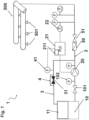
- the Fig. 1 shows a water extinguishing system 1 according to a preferred embodiment of the invention.
- the water extinguishing system 1 is a sprinkler system comprising a plurality of sprinklers 501, which are supplied with an extinguishing fluid via a pipe system 500.
- the extinguishing fluid is provided by a fluid supply, which in the exemplary embodiment of the Fig. 1 is designed as a fluid supply tank 10.
- the fluid supply tank 10 is connected to the pipe system 500 via a supply line 2 in order to supply the pipe system 500 with extinguishing fluid.
- the supply line 2 is preferably designed as a pipe in which a shut-off valve 101, a pressure indicator 102, a pump 20, a backflow preventer 50, and a shut-off valve 51 are arranged.
- the pump 20 serves to pump the extinguishing fluid from the fluid supply container 10.
- the pump 20 is designed as a sprinkler pump.
- a test line 3 branches off from the supply line 2, which includes a shut-off device 31. According to the prior art, this test line 3 was used to conduct a pump test run, for which purpose the opening device 31 is moved from a blocking position to an unlocking position in order to open a test circuit. However, it should be understood at this point that such an opening of the test line 3 is no longer necessary to conduct the pump test run according to the invention.
- the test line 3 is designed to direct the extinguishing fluid delivered by the pump 20 into a fluid reservoir 11.
- This fluid reservoir is fluidly connected to the fluid supply container 10, so that the extinguishing fluid is fed back into the fluid supply.
- the test line 3 can also be designed such that the extinguishing fluid passed through it is lost from the extinguishing circuit by being directed into a drain.
- the fluid diversion line 4 branches off from the test line 3. In other embodiments, however, the fluid diversion line may alternatively or additionally branch off from the supply line 2, as long as it allows part of the extinguishing fluid to be diverted around the opening member when the extinguishing fluid is pumped by the pump 20.
- the water extinguishing system 1 further comprises a pump control 21 with a pressure switch 22.
- the pump control 21 is used to start the pump 20. If a pump test run is to be carried out, this is done in the Fig. 1 by reducing the pressure detected by pressure switch 22. This pressure drop triggers pressure switch 22, activating pump control 21 and thus pump 20. Pump 20 now begins to operate and thus pump extinguishing fluid. Since shutoff valve 51 to the pipe system is closed, the extinguishing fluid is directed through test line 3, where it is routed via fluid diversion 4.
- the pump control 21 comprises a module which comprises the control unit 211.
- the control unit 211 is in communicative signal connection with the flow sensor 41, which is arranged on the sample line 3.
- Flow sensor 41 and control unit 211 form the control device for controlling the pump test run.
- the flow sensor 41 is configured to determine the flow rate per unit of time of the extinguishing fluid pumped by the pump 20 and thus to determine a parameter indicative of the cross-section of the fluid bypass 4. The value of this parameter is then evaluated by the control unit 211. Based on this evaluation, the control unit 211 controls the pump test run of the pump 20. In particular, the control unit determines whether the pump test run should be aborted because of faults that could lead to damage to the pump, or whether the pump test run should not be started at all because of such faults, or whether the pump test run can be carried out as planned. In the latter case, the control unit deactivates the pump 20 after the pump test run has been successfully completed—i.e., after the operating parameters of the pump 20 have been reached.
- the pump test run is controlled by a control device comprising a control unit 211 and a flow sensor, wherein the A parameter indicative of the cross-section of the fluid bypass 4 is a flow parameter.
- the extinguishing fluid pumped by the pump 20 during the pump test run is diverted via the fluid bypass 4, which in this way prevents damage to the pump.
- the pump test run according to the invention is thus carried out using the fluid bypass 4.
- the fluid bypass 4 rather than the test line 3, is used to divert the extinguishing fluid away from the pump during the pump test run. Since the fluid bypass 4, unlike the test line, always carries extinguishing fluid, the pump test run can also be carried out without opening a corresponding opening element.
- the water extinguishing system 1 of the Fig. 1 thus enables an automatic pump test run, during which it can be ensured that even in the event of a fire or in the event of a power failure, the water extinguishing system 1 has sufficient extinguishing fluid available for fire fighting, and that the pump 20 is controlled in such a way that it remains active in the event of a fire, even when the pump test run has been completed.
- the Fig. 1 shows a water extinguishing system 1 according to a preferred embodiment of the invention.
- the water extinguishing system 1 is a sprinkler system comprising a plurality of sprinklers 501, which are supplied with an extinguishing fluid via a pipe system 500.
- the extinguishing fluid is provided by a fluid supply, which in the exemplary embodiment of the Fig. 1 is designed as a fluid supply tank 10.
- the fluid supply tank 10 is connected to the pipe system 500 via a supply line 2 in order to supply the pipe system 500 with extinguishing fluid.
- the supply line 2 is preferably designed as a pipe in which a shut-off valve 101, a pressure indicator 102, a pump 20, a backflow preventer 50, and a shut-off valve 51 are arranged.
- the pump 20 serves to pump the extinguishing fluid from the fluid supply container 10.
- the pump 20 is designed as a sprinkler pump.
- a test line 3 branches off from the supply line 2, which includes a shut-off device 31. According to the prior art, this test line 3 was used to conduct a pump test run, for which purpose the opening device 31 is moved from a shut-off position to an unlocked position in order to open a test circuit.
- the test line 3 is designed to direct the extinguishing fluid delivered by the pump 20 into a fluid reservoir 11.
- This fluid reservoir is fluidly connected to the fluid supply container 10, so that the extinguishing fluid is fed back into the fluid supply.
- the test line 3 can also be designed such that the extinguishing fluid passed through it is lost from the extinguishing circuit by being directed into a drain.
- the opening member 31 In the blocking position of the opening member 31, the opening member 31 is positioned so that no fluid flow can take place through the test line 3. However, a fluid bypass 4 branches off from the test line 3, which in the embodiment of the Fig. 1 has a cross-section 98% smaller than that of the test line 3. This fluid diversion 4 allows a small portion of the extinguishing fluid to flow around the opening element and thus into the fluid reservoir 11.
- the fluid diversion line 4 branches off from the test line 3. In other embodiments, however, the fluid diversion line may alternatively or additionally branch off from the supply line 2, as long as it allows part of the extinguishing fluid to be diverted around the opening member when the extinguishing fluid is pumped by the pump 20.
- the water extinguishing system 1 further comprises a pump control 21 with a pressure switch 22.
- the pump control 21 is used to start the pump 20. If a pump test run is to be carried out, this is done in the Fig. 1 by reducing the pressure detected by pressure switch 22. This pressure drop triggers pressure switch 22, activating pump control 21 and thus pump 20. Pump 20 now begins to operate and thus pump extinguishing fluid. Since shutoff valve 51 to the pipe system is closed, the extinguishing fluid is directed through test line 3, where it is routed via fluid diversion 4.
- the pump control 21 comprises a module which comprises the control unit 211.
- the control unit 211 is in communicative Signal connection with the flow sensor 41, which is arranged on the sample line 3.
- Flow sensor 41 and control unit 211 form the control device for controlling the pump test run.
- the flow sensor 41 is configured to determine the flow rate per unit of time of the extinguishing fluid pumped by the pump 20 and thus to determine a parameter indicative of the cross-section of the fluid bypass 4. The value of this parameter is then evaluated by the control unit 211. Based on this evaluation, the control unit 211 controls the pump test run of the pump 20. In particular, the control unit determines whether the pump test run should be aborted because of faults that could lead to damage to the pump, or whether the pump test run should not be started at all because of such faults, or whether the pump test run can be carried out as planned. In the latter case, the control unit deactivates the pump 20 after the pump test run has been successfully completed—i.e., after the operating parameters of the pump 20 have been reached.
- the pump test run is thus controlled by a control device comprising a control unit 211 and a flow sensor, wherein the parameter indicative of the cross-section of the fluid bypass 4 is a flow parameter.
- the extinguishing fluid pumped by the pump 20 during the pump test run is diverted via the fluid bypass 4, thus preventing damage to the pump.
- the water extinguishing system 1 of the Fig. 1 thus enables an automatic pump test run, during which it can be ensured that even in the event of a fire or in the event of a power failure, the water extinguishing system 1 has sufficient extinguishing fluid available for fire fighting, and that the pump 20 is controlled in such a way that it remains active in the event of a fire, even when the pump test run has been completed.
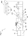
- the Fig. 2 shows a water extinguishing system 1' according to a further preferred embodiment of the invention.
- the embodiment of the Fig. 2 is in many ways parallel to the design of the Fig. 1 , wherein the same components are designated by the same reference numerals.
- the water extinguishing system 1' also comprises a fluid supply container 10, a fluid reservoir 11, a supply line 2 to a pipe system 500 with a shut-off valve 101, a pressure indicator 102, a pump 20, a backflow preventer 50 and a second shut-off valve 51.
- the pump 20 is controlled by the pump control 21 comprising the control unit 211 and connected to the pressure switch 22.
- the functionalities of these elements corresponding to those of the embodiment of the Fig. 1 , which is why a more detailed description is omitted here.
- the water extinguishing system 1' of the Fig. 2 is set up for an automatic pump test run, which, as described in connection with the Fig. 1 described, is started by the pump control 21 by means of the pressure switch 22. Also in the embodiment of the Fig. 2 The water extinguishing system 1' comprises a test line 3 with an opening element 31 and a fluid diversion 4. However, in the embodiment of the Fig. 2 No flow sensor 41 is arranged on the test line.
- the water extinguishing system 1' comprises a pressure difference sensor 42, which is configured to determine a first pressure value at a first position 43 at a first end of the fluid bypass 4, more precisely at a branch of the fluid bypass 4 from the test line 3, and to determine a second pressure value at a second position 44 at a second end of the fluid bypass 4, more precisely at the branch of the fluid bypass 4 to the test line 3.
- the pressure difference sensor 42 thus allows the pressure difference between a position at the beginning of the fluid bypass 4 and a position at the end of the fluid bypass 4 to be determined. This enables the measurement of a pressure loss of the extinguishing fluid along the fluid bypass 4. This, in turn, allows conclusions to be drawn about the properties of the cross-section of the fluid bypass 4.
- the pressure difference is transmitted from the pressure difference sensor 42 to the control unit 211 in the pump control system 21.
- the control unit 211 evaluates the determined pressure difference and thus determines whether the cross-section of the fluid diversion is sufficient to reliably divert the extinguishing fluid pumped by the pump 20 during the pump test run away from this pump and thus prevent damage to the pump 20.
- control unit 211 is preferably configured to compare the value of the pressure difference with a previously defined limit value.
- This limit value can, in particular, specify a maximum value for the pressure difference. If the value of the pressure difference exceeds this maximum value, this indicates that the cross-section of the fluid bypass 4 is insufficient to prevent damage to the pump.
- control unit 211 is configured to output a signal that aborts the pump test run. If the pump test run has not yet started, this signal may also prevent the pump from starting at all.
- the pump test run can be carried out until the working parameters of the pump 20 are reached and is then regularly terminated by the control unit 211 of the control device.
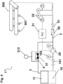
- Fig. 3 shows a water extinguishing system 1" according to a further preferred embodiment.
- the water extinguishing system 1" also comprises a fluid supply container 10, a fluid reservoir 11, a supply line 2 to a pipe system 500 with a first shut-off valve 101, a pressure indicator 102, a pump 20, a backflow preventer 50 and a second shut-off valve 51.
- the pump 20 is controlled by the pump control 21 comprising the control unit 211 and connected to the pressure switch 22.
- the water extinguishing system 1" comprises a temperature sensor 23, which is in communicative signal connection with the control unit 211 and together with it forms the control device for controlling the pump test run.
- the temperature sensor 23 is arranged at an outlet of the pump 20 and is configured to determine the temperature of the extinguishing fluid that was pumped by the pump 20. This allows the temperature of the pump 20 to be determined indirectly and thus to determine whether the guidance of the extinguishing fluid pumped by the pump 20 is sufficient to protect it from running dry and/or overheating - and therefore from damage.
- a temperature sensor 23 is used to detect any damage to the pump 20, it should be understood that, alternatively or additionally, a noise sensor and/or a vibration sensor may also be used to monitor the condition of the pump. Such a noise sensor and/or a vibration sensor would also be arranged similarly to the temperature sensor. Preferably, a noise and/or vibration sensor can also be arranged directly on the pump housing.
- the measured temperature is transmitted to the control unit 211.
- the control unit 211 is configured to compare the temperature with a temperature limit. If this temperature limit is exceeded, it means that the extinguishing fluid – and therefore also the pump 20 – has become too hot. If this is the case, The control unit 211 outputs a signal that aborts a pump test run that has already started or prevents a pump test run from being started. However, if the temperature falls below the temperature limit, the control unit 211 allows the pump test run to continue until the pump's operating parameters are reached and only then outputs a signal to terminate the pump test run.
- Fig. 4 shows a water extinguishing system 1′′′ according to yet another preferred embodiment, comprising a supply line 2, a test line 3, a fluid bypass line 4, a pump 20, a pipe system 500, a fluid supply container 10, and a fluid reservoir 11, as described above.
- identical elements are designated by identical reference numerals.
- a first shut-off valve 101, a pressure indicator 102, a backflow preventer 50, and a second shut-off valve 51 are also arranged along the supply line 2, and the pump 20 is activated by a pump control 21 with a pressure switch 22.
- the control device is no longer designed as a combination of a control unit 211 and a sensor, but as a switching arrangement 212, which is arranged on the fluid diversion 4 and comprises a flow switch, which is designed to switch from a deactivation position to an activation position at a certain flow rate of the extinguishing fluid through the fluid diversion 4.
- a switching arrangement 212 which is arranged on the fluid diversion 4 and comprises a flow switch, which is designed to switch from a deactivation position to an activation position at a certain flow rate of the extinguishing fluid through the fluid diversion 4.
- the switching arrangement 212 either does not switch to the activation position from the outset or switches back to the deactivation position, whereby the pump test run of the pump 20 is either not started at all or is aborted.
- the switching arrangement 212 thus prevents damage to the pump due to an insufficient extinguishing fluid line.
- the flow switch of the switching arrangement 212 remains in the activated position. This ensures that the pump is not switched off after the (supposed) completion of the pump test run, but continues to pump extinguishing fluid to fight the fire. This arrangement can therefore ensure operational readiness in the event of a fire.
- the Fig. 5 shows a water extinguishing system 1"" according to yet another preferred embodiment.
- the water extinguishing system 1"" corresponds in its arrangement with regard to the sensors and its functioning to the water extinguishing system 1′′′ of Fig. 4 with the difference that the fluid diversion 4 in the water extinguishing system 1"" of the Fig. 5 branches off from the supply line 2 in order to guide the extinguishing fluid around the shut-off device 31 of the test line 3 away from the pipe system 500.
- the thus modified arrangement of the fluid diversion 4 has no influence on the above-mentioned in connection with the Fig. 4 described pump test run.
- a combination of the sensor arrangements and/or configurations of the fluid diversion 4 and/or the sampling line 3 according to the exemplary embodiments of the Figures 1 to 5 is conceivable.
- a combination of a temperature sensor in the vicinity of the pump 20 with a pressure difference sensor on the fluid bypass 4 can be used to ensure improved monitoring of the pump test run.
- This combination can further be combined with a flow sensor on the fluid bypass 4 and/or a vibration sensor on the pump 20 and/or a noise sensor on or in the vicinity of the pump 20 to further improve monitoring. improve.
- Further combinations which will become immediately apparent to the person skilled in the art after studying the above description, are also contemplated within the meaning of the invention.
Landscapes
- Health & Medical Sciences (AREA)
- Public Health (AREA)
- Business, Economics & Management (AREA)
- Emergency Management (AREA)
- Control Of Positive-Displacement Pumps (AREA)
- Fire-Extinguishing By Fire Departments, And Fire-Extinguishing Equipment And Control Thereof (AREA)
Applications Claiming Priority (2)
| Application Number | Priority Date | Filing Date | Title |
|---|---|---|---|
| DE102019135815.9A DE102019135815B3 (de) | 2019-12-27 | 2019-12-27 | Wasserlöschanlage, Steuereinrichtung, Gefahrenmeldezentrale, Verfahren zum Steuern eines Pumpentestlaufs in einer Wasserlöschanlage und Verwendung einer Fluidumleitung in einer Wasserlöschanlage für einen Pumpentestlauf einer Pumpe |
| EP20211241.3A EP3842101A1 (fr) | 2019-12-27 | 2020-12-02 | Système d'extinction d'eau et procede de controle d`un test de pompe dans un système d'extinction d'eau |
Related Parent Applications (1)
| Application Number | Title | Priority Date | Filing Date |
|---|---|---|---|
| EP20211241.3A Division EP3842101A1 (fr) | 2019-12-27 | 2020-12-02 | Système d'extinction d'eau et procede de controle d`un test de pompe dans un système d'extinction d'eau |
Publications (2)
| Publication Number | Publication Date |
|---|---|
| EP4556080A2 true EP4556080A2 (fr) | 2025-05-21 |
| EP4556080A3 EP4556080A3 (fr) | 2025-08-13 |
Family
ID=73547495
Family Applications (3)
| Application Number | Title | Priority Date | Filing Date |
|---|---|---|---|
| EP25161899.7A Pending EP4556080A3 (fr) | 2019-12-27 | 2020-12-02 | Installation d'extinction d'eau et procédé de commande d'un cycle d'essai de pompe dans une installation d'extinction d'eau |
| EP25161902.9A Pending EP4556081A3 (fr) | 2019-12-27 | 2020-12-02 | Installation d'extinction d'eau et procédé de commande d'un cycle d'essai de pompe dans une installation d'extinction d'eau |
| EP20211241.3A Pending EP3842101A1 (fr) | 2019-12-27 | 2020-12-02 | Système d'extinction d'eau et procede de controle d`un test de pompe dans un système d'extinction d'eau |
Family Applications After (2)
| Application Number | Title | Priority Date | Filing Date |
|---|---|---|---|
| EP25161902.9A Pending EP4556081A3 (fr) | 2019-12-27 | 2020-12-02 | Installation d'extinction d'eau et procédé de commande d'un cycle d'essai de pompe dans une installation d'extinction d'eau |
| EP20211241.3A Pending EP3842101A1 (fr) | 2019-12-27 | 2020-12-02 | Système d'extinction d'eau et procede de controle d`un test de pompe dans un système d'extinction d'eau |
Country Status (4)
| Country | Link |
|---|---|
| US (3) | US11691042B2 (fr) |
| EP (3) | EP4556080A3 (fr) |
| CN (1) | CN216319701U (fr) |
| DE (1) | DE102019135815B3 (fr) |
Families Citing this family (12)
| Publication number | Priority date | Publication date | Assignee | Title |
|---|---|---|---|---|
| DE102020106193A1 (de) | 2020-03-06 | 2021-09-09 | Minimax Viking Research & Development Gmbh | Fernüberwachung eines Rohrnetzwerks mittels Sensoren |
| DE102020111756A1 (de) | 2020-04-30 | 2021-11-25 | Minimax Viking Research & Development Gmbh | Verfahren und System zum Überwachen einer Brandschutzanlage, sowie entsprechende Brandschutzanlage |
| WO2023086138A1 (fr) * | 2021-11-15 | 2023-05-19 | Siemens Industry, Inc. | Système d'extincteur d'incendie pour la gestion de bâtiments |
| US12186611B2 (en) | 2021-11-15 | 2025-01-07 | Siemens Industry, Inc. | Fire sprinkler system for building management |
| CN114146353B (zh) * | 2021-12-03 | 2022-09-16 | 辰安天泽智联技术有限公司 | 一种建筑消防给水系统的自动诊断系统和自动诊断方法 |
| CN114705462B (zh) * | 2022-02-28 | 2023-10-20 | 正帆百泰(苏州)科技有限公司 | 一种测试装置 |
| CN114593114B (zh) * | 2022-03-21 | 2024-09-20 | 中铁工程装备集团有限公司 | 一种多泵组合液压源的性能多维感知系统 |
| DE102022115301B4 (de) | 2022-06-20 | 2024-08-14 | Mecon Gmbh | Druckschaltvorrichtung, Wasserlöschanlage, Verfahren zur Überwachung einer Druckschaltvorrichtung und Verfahren zum Starten mindestens einer Pumpe einer Wasserlöschanlage |
| DE102022115300B4 (de) | 2022-06-20 | 2024-08-14 | Mecon Gmbh | Druckschaltvorrichtung, Wasserlöschanlage und Verfahren zum Start eines Pumpentestlaufes |
| EP4393555A1 (fr) * | 2022-12-27 | 2024-07-03 | Minimax Viking Research & Development GmbH | Système d'extinction d'eau et procédé pour effectuer une opération de pompe dans celui-ci |
| EP4477277A3 (fr) * | 2023-02-15 | 2025-03-19 | MECON GmbH | Installation d'extinction et procédé de fonctionnement d'une telle installation d'extinction |
| DE102024111475A1 (de) * | 2024-04-24 | 2025-10-30 | Mecon Gmbh | Überwachungsvorrichtung und Verfahren für einen Sprinklerpumpentestlauf |
Family Cites Families (14)
| Publication number | Priority date | Publication date | Assignee | Title |
|---|---|---|---|---|
| JPS585064B2 (ja) | 1980-10-21 | 1983-01-28 | ホーチキ株式会社 | 消火装置 |
| DE8427006U1 (de) * | 1984-09-13 | 1985-02-07 | Bender, Dieter, 7551 Bischweier | Pumpentesteinrichtung |
| GB2280369B (en) * | 1993-07-29 | 1997-03-05 | Project Fire Engineers Limited | Fire sprinkler systems |
| DE4439882C2 (de) * | 1994-11-08 | 1996-12-12 | Verband Der Sachversicherer Ev | Verfahren und Vorrichtung zur Versorgung von Sprinkleranlagen in hohen Wohn- und/oder Bürogebäuden mit Löschflüssigkeit |
| US5950150A (en) | 1996-07-05 | 1999-09-07 | Lloyd; Steven J. | Fire/life safety system operation criteria compliance verification system and method |
| GB0017935D0 (en) | 2000-07-22 | 2000-09-13 | Project Fire Engineers Limited | Testing fluid systems |
| DE102005024170A1 (de) | 2005-05-13 | 2006-11-16 | G + S Brandschutz Gmbh | Brandschutzeinrichtung |
| DE102006032648B4 (de) | 2006-01-30 | 2014-06-26 | Abb Research Ltd. | Diagnosesystem und Verfahren zur Zustandsüberwachung und Erkennung von Funktionsminderungen und Ausfällen an verdichtende und rotierende Maschinen |
| PL1972793T3 (pl) | 2007-03-23 | 2010-12-31 | Grundfos Management As | Sposób wykrywania usterek w zespołach pompowych |
| DE102008050126B4 (de) | 2008-10-06 | 2012-11-22 | Hekatron Vertriebs Gmbh | Vorrichtung zum Anzeigen von Zuständen und Steuern einer Sprinklerstation |
| US9375595B2 (en) | 2011-01-27 | 2016-06-28 | Jeremy Taylor | Self-testing and self-calibrating fire sprinkler system, method of installation and method of use |
| US8573315B1 (en) | 2012-10-23 | 2013-11-05 | W. S. Darley & Co. | Self-testing and self-calibrating fire sprinkler system, method of installation and method of use |
| CN208582904U (zh) * | 2018-07-17 | 2019-03-08 | 北京紫光新锐科技发展有限公司 | 一种智能型电路板数字巡检控制柜 |
| DE102018119776A1 (de) | 2018-08-14 | 2020-02-20 | Minimax Viking Research & Development Gmbh | Wasserlöschanlage und zugehöriges Verfahren zum Kontrollieren der Wasserlöschanlage |
-
2019
- 2019-12-27 DE DE102019135815.9A patent/DE102019135815B3/de active Active
-
2020
- 2020-11-05 US US17/090,496 patent/US11691042B2/en active Active
- 2020-12-02 EP EP25161899.7A patent/EP4556080A3/fr active Pending
- 2020-12-02 EP EP25161902.9A patent/EP4556081A3/fr active Pending
- 2020-12-02 EP EP20211241.3A patent/EP3842101A1/fr active Pending
- 2020-12-21 CN CN202023094359.XU patent/CN216319701U/zh active Active
-
2023
- 2023-05-17 US US18/318,786 patent/US12168156B2/en active Active
-
2024
- 2024-10-03 US US18/905,397 patent/US20250170443A1/en active Pending
Also Published As
| Publication number | Publication date |
|---|---|
| EP4556081A3 (fr) | 2025-08-13 |
| US12168156B2 (en) | 2024-12-17 |
| EP4556081A2 (fr) | 2025-05-21 |
| US20250170443A1 (en) | 2025-05-29 |
| US20230364459A1 (en) | 2023-11-16 |
| US20210197004A1 (en) | 2021-07-01 |
| US11691042B2 (en) | 2023-07-04 |
| CN216319701U (zh) | 2022-04-19 |
| EP4556080A3 (fr) | 2025-08-13 |
| DE102019135815B3 (de) | 2020-12-17 |
| EP3842101A1 (fr) | 2021-06-30 |
Similar Documents
| Publication | Publication Date | Title |
|---|---|---|
| DE102019135815B3 (de) | Wasserlöschanlage, Steuereinrichtung, Gefahrenmeldezentrale, Verfahren zum Steuern eines Pumpentestlaufs in einer Wasserlöschanlage und Verwendung einer Fluidumleitung in einer Wasserlöschanlage für einen Pumpentestlauf einer Pumpe | |
| EP3713649B1 (fr) | Installation d'extinction à eau et procédé correspondant pour le contrôle de l'installation d'extinction à eau | |
| DE3817411C2 (fr) | ||
| DE102010013982A1 (de) | Vorrichtung zum Erzeugen von Schaumbitumen und Verfahren zu deren Wartung | |
| DE10318671B4 (de) | Zentralschmieranlage, insbesondere für Maschinen, Fahrzeuge, Bau- oder Landmaschinen | |
| WO2011061005A1 (fr) | Agencement de débitmètre à auto-surveillance et procédé de fonctionnement associé | |
| DE69801419T2 (de) | Kraftstoffzapfsäule | |
| EP1861176B1 (fr) | Valve d'entretien facile destinee a des systemes de lutte contre un incendie | |
| EP2131172B1 (fr) | Dispositif de commande de gaz à l'aide d'un contrôle d'étanchéité | |
| DE19923296A1 (de) | Anlage mit Prüfeinrichtung | |
| EP3407981B1 (fr) | Installation d'extinction par brouillard | |
| WO2018192953A1 (fr) | Installation d'extinction d'incendie, système d'extinction d'incendie comportant cette dernière, ainsi que procédé pour la détermination de la propagation d'un feu | |
| EP1106904A2 (fr) | Procédé et dispositif pour localiser des pertes de pression | |
| DE102011119307B4 (de) | Verfahren zum Erfassen der Ventilstellung wenigstens eines Ablassventils | |
| CH623912A5 (en) | Monitoring device at the supply line of an oil-fed unit | |
| WO2015106872A1 (fr) | Système de piles à combustible comportant au moins un empilement de piles à combustible intégré dans un boîtier | |
| EP2468391B1 (fr) | Dispositif d'établissement du taux de mélange d'un injecteur dans une conduite d'extinction | |
| DE10348806B3 (de) | Hochdruckwasserstrahl-Anlage mit Prüfdüse | |
| DE102021203712A1 (de) | Wärmepumpensystem und Verfahren zum Betreiben eines Wärmepumpensystems | |
| DE112005003121T5 (de) | Brennstoffzellensystem und Verfahren zum Überprüfen eines Austretens von Gas aus demselben | |
| DE102022115301B4 (de) | Druckschaltvorrichtung, Wasserlöschanlage, Verfahren zur Überwachung einer Druckschaltvorrichtung und Verfahren zum Starten mindestens einer Pumpe einer Wasserlöschanlage | |
| DE19850588C1 (de) | Durchflußmengenbegrenzer | |
| EP4477277A2 (fr) | Installation d'extinction et procédé de fonctionnement d'une telle installation d'extinction | |
| DE102024101000A1 (de) | Löschanlage und Verfahren zum Betreiben einer solchen | |
| EP4143525A1 (fr) | Procédé et système de surveillance d'une installation de protection contre les incendies, et installation de protection contre les incendies correspondante |
Legal Events
| Date | Code | Title | Description |
|---|---|---|---|
| PUAI | Public reference made under article 153(3) epc to a published international application that has entered the european phase |
Free format text: ORIGINAL CODE: 0009012 |
|
| STAA | Information on the status of an ep patent application or granted ep patent |
Free format text: STATUS: THE APPLICATION HAS BEEN PUBLISHED |
|
| AC | Divisional application: reference to earlier application |
Ref document number: 3842101 Country of ref document: EP Kind code of ref document: P |
|
| AK | Designated contracting states |
Kind code of ref document: A2 Designated state(s): AL AT BE BG CH CY CZ DE DK EE ES FI FR GB GR HR HU IE IS IT LI LT LU LV MC MK MT NL NO PL PT RO RS SE SI SK SM TR |
|
| REG | Reference to a national code |
Ref country code: DE Ref legal event code: R079 Free format text: PREVIOUS MAIN CLASS: A62C0037500000 Ipc: A62C0035580000 |
|
| PUAL | Search report despatched |
Free format text: ORIGINAL CODE: 0009013 |
|
| AK | Designated contracting states |
Kind code of ref document: A3 Designated state(s): AL AT BE BG CH CY CZ DE DK EE ES FI FR GB GR HR HU IE IS IT LI LT LU LV MC MK MT NL NO PL PT RO RS SE SI SK SM TR |
|
| RIC1 | Information provided on ipc code assigned before grant |
Ipc: A62C 35/58 20060101AFI20250709BHEP Ipc: A62C 35/68 20060101ALI20250709BHEP Ipc: A62C 37/50 20060101ALI20250709BHEP |
|
| STAA | Information on the status of an ep patent application or granted ep patent |
Free format text: STATUS: REQUEST FOR EXAMINATION WAS MADE |
|
| 17P | Request for examination filed |
Effective date: 20260213 |