EP4556092A1 - Filtration des effluents d'une machine à laver à travers une brosse hélicoïdale - Google Patents
Filtration des effluents d'une machine à laver à travers une brosse hélicoïdale Download PDFInfo
- Publication number
- EP4556092A1 EP4556092A1 EP23383164.3A EP23383164A EP4556092A1 EP 4556092 A1 EP4556092 A1 EP 4556092A1 EP 23383164 A EP23383164 A EP 23383164A EP 4556092 A1 EP4556092 A1 EP 4556092A1
- Authority
- EP
- European Patent Office
- Prior art keywords
- flow channel
- filter
- brush
- tube
- filter assembly
- Prior art date
- Legal status (The legal status is an assumption and is not a legal conclusion. Google has not performed a legal analysis and makes no representation as to the accuracy of the status listed.)
- Withdrawn
Links
Images


Classifications
-
- B—PERFORMING OPERATIONS; TRANSPORTING
- B01—PHYSICAL OR CHEMICAL PROCESSES OR APPARATUS IN GENERAL
- B01D—SEPARATION
- B01D35/00—Filtering devices having features not specifically covered by groups B01D24/00 - B01D33/00, or for applications not specifically covered by groups B01D24/00 - B01D33/00; Auxiliary devices for filtration; Filter housing constructions
- B01D35/10—Brush filters ; Rotary brush filters
-
- B—PERFORMING OPERATIONS; TRANSPORTING
- B01—PHYSICAL OR CHEMICAL PROCESSES OR APPARATUS IN GENERAL
- B01D—SEPARATION
- B01D35/00—Filtering devices having features not specifically covered by groups B01D24/00 - B01D33/00, or for applications not specifically covered by groups B01D24/00 - B01D33/00; Auxiliary devices for filtration; Filter housing constructions
- B01D35/02—Filters adapted for location in special places, e.g. pipe-lines, pumps, stop-cocks
-
- D—TEXTILES; PAPER
- D06—TREATMENT OF TEXTILES OR THE LIKE; LAUNDERING; FLEXIBLE MATERIALS NOT OTHERWISE PROVIDED FOR
- D06F—LAUNDERING, DRYING, IRONING, PRESSING OR FOLDING TEXTILE ARTICLES
- D06F39/00—Details of washing machines not specific to a single type of machines covered by groups D06F9/00 - D06F27/00
- D06F39/10—Filtering arrangements
-
- A—HUMAN NECESSITIES
- A47—FURNITURE; DOMESTIC ARTICLES OR APPLIANCES; COFFEE MILLS; SPICE MILLS; SUCTION CLEANERS IN GENERAL
- A47L—DOMESTIC WASHING OR CLEANING; SUCTION CLEANERS IN GENERAL
- A47L15/00—Washing or rinsing machines for crockery or tableware
- A47L15/42—Details
- A47L15/4202—Water filter means or strainers
-
- B—PERFORMING OPERATIONS; TRANSPORTING
- B01—PHYSICAL OR CHEMICAL PROCESSES OR APPARATUS IN GENERAL
- B01D—SEPARATION
- B01D2201/00—Details relating to filtering apparatus
- B01D2201/29—Filter cartridge constructions
- B01D2201/291—End caps
- B01D2201/296—Other than having a circular shape
-
- B—PERFORMING OPERATIONS; TRANSPORTING
- B01—PHYSICAL OR CHEMICAL PROCESSES OR APPARATUS IN GENERAL
- B01D—SEPARATION
- B01D2201/00—Details relating to filtering apparatus
- B01D2201/32—Flow characteristics of the filter
Definitions
- the present invention refers to a filter assembly for filtering effluent of a washing machine.
- US 2019/0126326 A1 discloses a fiber catcher for removing fibers, microfibers, hair and similar items from fluids, such as may be found in effluent pipes, streams, washing machines and clothes dryers.
- the fiber catcher includes a plurality of arms with a plurality of teeth for collecting fibers that are suspended in fluids.
- the fiber catcher is generally spherical. For use, the fiber catcher is placed in a drum of the washing machine together with clothing being washed.
- a length of the brush may be at least 20 times, preferably, at least 40 times, a cross-sectional width of the flow channel.
- the brush may comprise a central cord and bristles protruding from the central cord.
- the central cords facilitates insertion of the brush into the flow channel. Bristles protruding radially from the cord assist in guiding particles towards a circumferential delimitation of the flow channel or a border within the flow channel.
- the brush may be contained within a tube made from filter material, preferably nonwoven filter material.
- the brush spans across a diameter of the tube.
- the brush covers a cross section of the tube.
- the filter tube forms a border within the flow channel. Dirt in the effluent flowing into the first end of the filter tube is prevented from entering the flow channel due to the filter material. Effluent is filtered throughout the length of the filter tube. Filtered effluent may pass through the filter tube towards a circumferential delimitation of the flow channel and into an inner space of a support tube. This contributes to keep the pressure loss low. Energy consumption for filtering the effluent may be reduced. Further, the reduced pressure loss may avoid particles from being detached from the bristles of the brush. Consequently, filtration efficiency is enhanced.
- a maximum pore size of the filter tube may be 200 ⁇ m, preferably 100, particularly preferably 50 ⁇ m.
- the tube is preferably circumferentially sealed against a delimitation of the flow channel at the first end.
- the tube is detachable from the support unit. This may facilitate maintenance. During maintenance, the tube and brush are removed from the support unit. Then, a new tube with a pre-inserted brush is arranged in the flow channel, e.g. by winding the tube and brush assembly around a support tube of the support unit.
- the support unit may comprise a cylindrical support tube.
- the flow channel may be wound around the support tube.
- the support tube provides stability to the flow channel and the brush and tube, if present.
- the support tube may delimit the flow channel from an inner space of the support tube over at least part of its longitudinal extension.
- the support unit comprises a cover, which seals the support tube at a first face associated with the first end of the flow channel. This prevents unfiltered effluent to enter the inner space of the support tube. Rather, the unfiltered effluent is forced to enter the flow channel at its first end on the outside of the support tube.
- the support tube may have at least one flow opening (flow window), which fluidically connects an inner space of the support tube.
- the support tube may comprise longitudinal and circumferential ribs.
- the flow openings are formed between adjacent ribs. In other words, the open space between neighboring ribs presents the flow openings.
- This design keeps a large area of the support tube that is in contact with the flow channel open for filtered effluent to flow into the inner space of the support tube. Filtered effluent may pass into the inner space of the support tube through the openings between the longitudinal and circumferential ribs. Clean water may easily be drained from the inner space.
- At least one flow opening is provided in an end section of the flow channel associated with its second end. Preferably, a multitude of flow openings is provided along the length of the support tube, in particular along the entire longitudinal extension of the flow channel.
- the support unit may comprise a helical guiding element, which separates adjacent convolutions of the flow channel.
- the helical guiding element may radially protrude from a cylindrical support tube, with respect to an axis of the support tube.
- the helical guiding element may form a ramp, which descends along the support tube.
- the helical guiding element provides stability to the brush and, if present, a filter tube within the flow channel.
- the support unit may be a monolithic part, preferably an injection molded plastic part. This allows for cost efficient manufacturing of the support unit. Further, assembly and maintenance of the filter assembly may be facilitated, since less separate parts need be manipulated.
- the invention further relates to a filter module comprising a housing and a filter assembly according to the invention, as described above.
- the filter assembly is removably arranged inside the housing.
- the filter assembly is arranged inside the housing.
- the filter assembly is removed from the housing.
- the housing may have a cylindrical wall, which delimits the flow channel.
- the flow channel may be delimited towards the outside by the cylindrical wall of the housing and towards the inside at least partially be delimited by the cylindrical support tube. Adjacent convolutions of the flow channel may be delimited from one another by a helical guiding element.
- the housing may delimit part of a cross section of the flow channel, while the remainder of the flow channel's cross section may be defined by the support unit.
- the first end of the flow channel may be fluidically connected with an inlet port through an inlet opening in the cylindrical wall.
- This design may provide tangential infeeding of raw effluent. This contributes to keep pressure loss low, when guiding the effluent into the flow channel at its first end.
- the flow channel may surround an inner space, in particular the inner space of a support tube.
- the flow channel is generally fluidically connected with the inner space. After filtration through the brush and the tube, if present, in the flow channel, filtered effluent enters the inner space.
- the inner space is fluidically connected with an outlet port through an outlet opening arranged in a central portion of an end wall of the housing. This design allows in particular for draining of clean water from an inner space of a cylindrical support tube.
- the housing may have a removable closure. Removing the closure facilitates replacement of the brush and tube, if present.
- the filter assembly may be removed from the housing when the closure is detached.
- the closure may be removed and installed without tools.
- a handle may be provided to this end.
- a tool interface may be provided at the closure. Mating threads may be provided on the closure and housing.
- the invention also relates to the use of a filter module according to the invention, as described above, for filtering effluent of a washing machine. Thereby, the ecological impact of operating the washing machine may be reduced.
- the invention further relates to a washing machine comprising a filter module according to the invention, as described above.
- the washing machine typically comprises a water inlet for receiving clean water, a washing drum, and a water outlet for discharging wastewater.
- the filter module is fluidically arranged between the washing drum and the water outlet.
- effluent of the washing drum is directed through the filter assembly prior to being discharged via the water outlet.
- An inlet port of the filter module may receive effluent from the drum.
- An outlet port of the filter module may be connected to the water outlet of the washing machine. Alternatively, the outlet port of the filter module may present the water outlet of the washing machine.
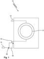
- FIG 1 shows a washing machine 10.
- the washing machine 10 comprises a rotatable drum 12 for receiving clothing or the like to be washed. Fresh water is fed into the drum 12 via a water inlet 14 of the washing machine 10. Wastewater (effluent) from the drum 12 is discharged into a sewage system (not depicted) via a water outlet 16 of the washing machine 10. Fluidically between the drum 12 and the water outlet 16 a filter module 20 is arranged.
- the filter module 20 may be arranged outside of the washing machine 10, as depicted in Figure 1 , or may be arranged within a housing of the washing machine 10 (not depicted). The filter module 20 prevents debris, which may contain microplastics, from being fed into the sewage system.
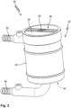
- FIGS 2 and 3 show the filter module 20 of the washing machine 10.
- the filter module 20 comprises a housing 22, which has a cylindrical wall 24.
- a removable closure 26 is attached to the cylindrical wall 24 at a top face via a threaded connection.
- the closure 26 is provided with a handle 28 and a tool interface 29, for removing and fastening it from or to the cylindrical wall 24.
- a bottom wall or end wall 30 is provided at a bottom face of the housing 22.
- An inlet port 32 allows raw effluent from the drum 12 to be fed into the housing 22 through an inlet opening 34 in the cylindrical wall 24.
- An outlet port 36 allows filtered effluent to be fed to the water outlet 16 through an outlet opening 38 in the center of end wall 30.
- a filter assembly 40 is removably arranged within the housing 22.
- the housing 22 is opened by detaching the closure 26.
- a support unit 42 of the filter assembly 40 comprises a cylindrical support tube 44, a cover 46 and a helical guiding element 48.
- the support tube 44 circumferentially surrounds an inner space 50.
- the cover 46 spans across the support tube 44 in order to separate the inner space 50 from an environment.
- the support tube 44 and the cylindrical wall 24 of the housing are arranged coaxial to one another around a common axis 52.
- the helical guiding element 48 radially protrudes from the support tube 44 and abuts the cylindrical wall 24.
- the guiding element 48 is wound around the support tube 44.
- the guiding element 48 is inclined against axis 52, such that it descends or ascends along the axis 52.
- a second face of the support tube 44 may be open; at the second face, the support tube 44 may sealingly rest on the end wall 30 of the housing 24.
- the support tube 44 may have a catch or sealing lip (not shown) that cooperates with a corresponding groove (not shown) at the end wall 30 of the housing 24 to seal the support tube 44 against the housing 24.
- the helical guiding element 48 separates adjacent convolutions (or revolutions) of a helical flow channel 54.
- the flow channel 54 is circumferentially bounded by the support tube 44 (towards the inside with respect to axis 52), by the cylindrical wall 24 (towards the outside with respect to axis 52), and by the helical guiding element 48 (in both directions along axis 52).
- the flow channel 54 comprises approiximately four and a half convolutions. The last convolution of the flow channel 54 may partially be delimited by the end wall 30 in downward direction of axis 52.
- the cylindrical wall 24 of housing 22 is impermeable for effluent.
- the guiding element 48 may be permeable or preferably impermeable.
- An impermeable guiding element 48 may sealingly abut the cylindrical wall 24.
- the support tube 44 is generally permeable for effluent at least in sections. In other words, the flow channel 54 may be open towards the inner space 50 of the support tube 44.
- a first end 56 of the flow channel 54 is associated with the inlet port 32 (note that the first end 56 is located behind the drawing plane of Figure 3 ).
- the first end 56 may be arranged just below the cover 46.
- the inlet opening 34 provides fluid communication between the inlet port 32 and the first end 56 of the flow channel 54.
- the cover 46 separates the inner space 50 from the inlet opening 34 and the inlet port 32. Thus, raw effluent is introduced into the flow channel 54 at its first end 56.
- a second end 58 of the flow channel 54 is associated with the outlet port 36.
- the support tube 44 is provided with flow openings 60.
- flow openings 60 are provided along the support tube 44 or flow channel 54, respectively (not depicted).
- the support tube 44 may comprise longitudinal and circumferential ribs along the radial body of the support tube 44, wherein the flow openings 60 are each provided between a pair of longitudinal ribs and a pair of circumferential ribs.
- the support tube 44 and the flow openings 60 provide fluid communication between the flow channel 54 and the inner space 50 of the support tube 44.
- the flow channel 54 is fluidically connected to the outlet port 36 via the flow openings 60, the inner space 50 and the outlet opening 38.
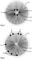
- a brush 62 is provided within the flow channel 54.
- the brush 62 extends from the first end 56 towards the second end 58, preferably all the way to the second end 58.
- the brush 62 to is arranged inside a tube 64, see also Figure 4 .
- the tube 64 is made from filter material, preferably nonwoven filter material.
- the tube 64 is contained within the flow channel 54 and extends from the first end 56 to the second end 58.
- the filter tube 68 is detachable from the support unit 42.
- the tube 64 is circumferentially (with respect to the cross section of the flow channel 54) sealed against the delimitation of the flow channel 54.
- the tube 64 may fill the flow channel 54 across its cross section; in other a free space 65 between the tube 64 and the delimitation of the flow channel 54, i.e. the support tube 44, the guiding element 48 and the cylindrical wall 24, may be filled with material of the tube 64, such as the nonwoven filter material remain.
- the brush 62 comprises a central cord 66 and bristles 68, which are fixed to the central cord 66 and protrude from the central cord 66. Free ends of (at least most of) the bristles 68 abut the filter tube 64. In other words, the brush 62 covers the cross section of the tube 64.
- the filter material of the tube 64 allows water to pass through, while retaining the particles 70 inside the tube 64.
- water travels along the flow channel 54 along the brush 62 within the tube 64.
- Clean water passes through the filter material of the tube 64 into the free space 65 between the tube 64 and the support unit 42 or the cylindrical housing wall 24.
- the clean water then flows from the free space 65 through the flow openings 60 into the inner space 50 of the support tube 44. Water which leaves the flow channel 54, has been filtered by passing through the brush 62 and/or the filter tube 64.
- the brush 62 or the inner surface of the tube 64 may become clogged with particles 70. Thus, maintenance of the filter module 20 is required.
- the closure 26 is unscrewed and the filter module 40 is removed from the housing 22.
- the used brush 62 and tube 64 are removed from the support unit 42, e.g. by unwinding them from the support tube 44.
- a new assembly of a brush 62 arranged in a tube 64 is wound around the support tube 44, so the tube-brush-assembly is arranged in the flow channel 54.
- the brush-tube-assembly may be pressed between the helical guiding element 48, preferably starting from the first end 56 of the flow channel 54 while working towards the second end 58.
- the filter assembly 40 is put back into the housing 22, while assuring that the closed end (i.e. cover 46) of the support tube 44 faces away from the end wall 30.
- a protrusion 72 on the end wall 30 may prevent full insertion of the filter assembly 40 in upside down orientation, cf. Figure 3 .
- Fully tightening the closure 26 is preferably possible, only if the filter assembly 40 is installed in the right orientation, i.e. with cover 46 facing the closure 26.
- a filter for effluent of washing machines comprises a helical flow channel.
- An elongate brush extends along the flow channel.
- the brush is contained within a filter tube.
- the brush can be replaced, while the filter tube is generally reused with a new brush.
- the brush and the filter tube capture fibres and particles such as microplasics, when effluent is fed through the flow channel.
- a support unit may at least partially define the cross section of the flow channel.
- the support unit is detachably arranged in a housing.
Landscapes
- Chemical & Material Sciences (AREA)
- Chemical Kinetics & Catalysis (AREA)
- Engineering & Computer Science (AREA)
- Textile Engineering (AREA)
- Water Supply & Treatment (AREA)
- Filtration Of Liquid (AREA)
- Filtering Materials (AREA)
Priority Applications (2)
| Application Number | Priority Date | Filing Date | Title |
|---|---|---|---|
| EP23383164.3A EP4556092A1 (fr) | 2023-11-15 | 2023-11-15 | Filtration des effluents d'une machine à laver à travers une brosse hélicoïdale |
| PCT/IB2024/060579 WO2025104528A1 (fr) | 2023-11-15 | 2024-10-28 | Filtration d'effluent d'une machine à laver au moyen d'une brosse hélicoïdale |
Applications Claiming Priority (1)
| Application Number | Priority Date | Filing Date | Title |
|---|---|---|---|
| EP23383164.3A EP4556092A1 (fr) | 2023-11-15 | 2023-11-15 | Filtration des effluents d'une machine à laver à travers une brosse hélicoïdale |
Publications (1)
| Publication Number | Publication Date |
|---|---|
| EP4556092A1 true EP4556092A1 (fr) | 2025-05-21 |
Family
ID=88837406
Family Applications (1)
| Application Number | Title | Priority Date | Filing Date |
|---|---|---|---|
| EP23383164.3A Withdrawn EP4556092A1 (fr) | 2023-11-15 | 2023-11-15 | Filtration des effluents d'une machine à laver à travers une brosse hélicoïdale |
Country Status (2)
| Country | Link |
|---|---|
| EP (1) | EP4556092A1 (fr) |
| WO (1) | WO2025104528A1 (fr) |
Citations (7)
| Publication number | Priority date | Publication date | Assignee | Title |
|---|---|---|---|---|
| US2468354A (en) * | 1944-08-18 | 1949-04-26 | Osborn Mfg Co | Filtration apparatus |
| US2984359A (en) * | 1957-10-25 | 1961-05-16 | Whirlpool Co | Laundry machine and filter therefor |
| JPS4835462U (fr) * | 1971-08-27 | 1973-04-27 | ||
| CN208144219U (zh) * | 2018-03-23 | 2018-11-27 | 天津歆毅翎科技有限公司 | 一种移动式养殖水过滤装置 |
| US20190126326A1 (en) | 2016-03-31 | 2019-05-02 | Rozalia Project Incorporated | Fiber catcher and method of removing fibers |
| CN110685127A (zh) | 2018-07-05 | 2020-01-14 | 青岛海尔洗衣机有限公司 | 过滤装置以及包含该过滤装置的衣物处理设备 |
| WO2021070102A1 (fr) | 2019-10-08 | 2021-04-15 | Inheriting earth Limited | Séparateur microplastique |
-
2023
- 2023-11-15 EP EP23383164.3A patent/EP4556092A1/fr not_active Withdrawn
-
2024
- 2024-10-28 WO PCT/IB2024/060579 patent/WO2025104528A1/fr active Pending
Patent Citations (7)
| Publication number | Priority date | Publication date | Assignee | Title |
|---|---|---|---|---|
| US2468354A (en) * | 1944-08-18 | 1949-04-26 | Osborn Mfg Co | Filtration apparatus |
| US2984359A (en) * | 1957-10-25 | 1961-05-16 | Whirlpool Co | Laundry machine and filter therefor |
| JPS4835462U (fr) * | 1971-08-27 | 1973-04-27 | ||
| US20190126326A1 (en) | 2016-03-31 | 2019-05-02 | Rozalia Project Incorporated | Fiber catcher and method of removing fibers |
| CN208144219U (zh) * | 2018-03-23 | 2018-11-27 | 天津歆毅翎科技有限公司 | 一种移动式养殖水过滤装置 |
| CN110685127A (zh) | 2018-07-05 | 2020-01-14 | 青岛海尔洗衣机有限公司 | 过滤装置以及包含该过滤装置的衣物处理设备 |
| WO2021070102A1 (fr) | 2019-10-08 | 2021-04-15 | Inheriting earth Limited | Séparateur microplastique |
Also Published As
| Publication number | Publication date |
|---|---|
| WO2025104528A1 (fr) | 2025-05-22 |
Similar Documents
| Publication | Publication Date | Title |
|---|---|---|
| US20240229338A9 (en) | Microplastic filter for a washing machine | |
| CA1314235C (fr) | Tamis autonettoyant | |
| EP3878536B1 (fr) | Dispositif d'aspiration à contre-courant pour appareil de filtration de tissu | |
| KR102388304B1 (ko) | 여과 장치 | |
| CN109107249A (zh) | 一种可自动清洗滤芯的过滤器及其工作方法 | |
| EP4556092A1 (fr) | Filtration des effluents d'une machine à laver à travers une brosse hélicoïdale | |
| CN117203389B (zh) | 洗衣机 | |
| CN219984137U (zh) | 滤芯可自清理的净水设备 | |
| CN106592169A (zh) | 用于洗衣机的排水组件及具有其的洗衣机 | |
| KR20210079729A (ko) | 의류처리장치 | |
| CN222111165U (zh) | 一种染色机用自清洁过滤器 | |
| JP6804089B2 (ja) | 糸巻フィルター、及びろ過モジュール | |
| CN217677061U (zh) | 一种脱水机的废水处理装置 | |
| JPH10113513A (ja) | 浄化装置 | |
| KR0126989Y1 (ko) | 용수 여과기 | |
| KR102448339B1 (ko) | 재생이 쉬운 가공액 필터 장치 | |
| KR960009122Y1 (ko) | Y형 원통 스트레이너(Strainer)의 자동세척장치 | |
| CN212417214U (zh) | 一种带式过滤机蒸汽吹洗总成 | |
| CN212067933U (zh) | 一种环境治理污水的过滤装置 | |
| KR19990003415U (ko) | 드럼식 세탁기의 잔수 누출 방지 이물질 수집장치 | |
| KR860001381B1 (ko) | 액체여과 장치 | |
| JP4245611B2 (ja) | 濾過蒸留装置、それに用いるフィルタ、およびドライクリーニング装置 | |
| KR950003951Y1 (ko) | 세탁기의 보푸라기 포집장치 | |
| SU1762975A1 (ru) | Фильтр | |
| WO2026044136A1 (fr) | Dispositif de raclage pour système de filtration à écoulement transversal tourbillonnaire |
Legal Events
| Date | Code | Title | Description |
|---|---|---|---|
| PUAI | Public reference made under article 153(3) epc to a published international application that has entered the european phase |
Free format text: ORIGINAL CODE: 0009012 |
|
| STAA | Information on the status of an ep patent application or granted ep patent |
Free format text: STATUS: THE APPLICATION HAS BEEN PUBLISHED |
|
| AK | Designated contracting states |
Kind code of ref document: A1 Designated state(s): AL AT BE BG CH CY CZ DE DK EE ES FI FR GB GR HR HU IE IS IT LI LT LU LV MC ME MK MT NL NO PL PT RO RS SE SI SK SM TR |
|
| STAA | Information on the status of an ep patent application or granted ep patent |
Free format text: STATUS: THE APPLICATION IS DEEMED TO BE WITHDRAWN |
|
| 18D | Application deemed to be withdrawn |
Effective date: 20251122 |