EP4556161A1 - Machine-outil - Google Patents
Machine-outil Download PDFInfo
- Publication number
- EP4556161A1 EP4556161A1 EP23209906.9A EP23209906A EP4556161A1 EP 4556161 A1 EP4556161 A1 EP 4556161A1 EP 23209906 A EP23209906 A EP 23209906A EP 4556161 A1 EP4556161 A1 EP 4556161A1
- Authority
- EP
- European Patent Office
- Prior art keywords
- axis
- workpiece table
- pivoting
- pivot support
- support
- Prior art date
- Legal status (The legal status is an assumption and is not a legal conclusion. Google has not performed a legal analysis and makes no representation as to the accuracy of the status listed.)
- Pending
Links
Images
Classifications
-
- B—PERFORMING OPERATIONS; TRANSPORTING
- B23—MACHINE TOOLS; METAL-WORKING NOT OTHERWISE PROVIDED FOR
- B23Q—DETAILS, COMPONENTS, OR ACCESSORIES FOR MACHINE TOOLS, e.g. ARRANGEMENTS FOR COPYING OR CONTROLLING; MACHINE TOOLS IN GENERAL CHARACTERISED BY THE CONSTRUCTION OF PARTICULAR DETAILS OR COMPONENTS; COMBINATIONS OR ASSOCIATIONS OF METAL-WORKING MACHINES, NOT DIRECTED TO A PARTICULAR RESULT
- B23Q5/00—Driving or feeding mechanisms; Control arrangements therefor
- B23Q5/02—Driving main working members
- B23Q5/04—Driving main working members rotary shafts, e.g. working-spindles
-
- B—PERFORMING OPERATIONS; TRANSPORTING
- B23—MACHINE TOOLS; METAL-WORKING NOT OTHERWISE PROVIDED FOR
- B23Q—DETAILS, COMPONENTS, OR ACCESSORIES FOR MACHINE TOOLS, e.g. ARRANGEMENTS FOR COPYING OR CONTROLLING; MACHINE TOOLS IN GENERAL CHARACTERISED BY THE CONSTRUCTION OF PARTICULAR DETAILS OR COMPONENTS; COMBINATIONS OR ASSOCIATIONS OF METAL-WORKING MACHINES, NOT DIRECTED TO A PARTICULAR RESULT
- B23Q39/00—Metal-working machines incorporating a plurality of sub-assemblies, each capable of performing a metal-working operation
-
- B—PERFORMING OPERATIONS; TRANSPORTING
- B23—MACHINE TOOLS; METAL-WORKING NOT OTHERWISE PROVIDED FOR
- B23Q—DETAILS, COMPONENTS, OR ACCESSORIES FOR MACHINE TOOLS, e.g. ARRANGEMENTS FOR COPYING OR CONTROLLING; MACHINE TOOLS IN GENERAL CHARACTERISED BY THE CONSTRUCTION OF PARTICULAR DETAILS OR COMPONENTS; COMBINATIONS OR ASSOCIATIONS OF METAL-WORKING MACHINES, NOT DIRECTED TO A PARTICULAR RESULT
- B23Q1/00—Members which are comprised in the general build-up of a form of machine, particularly relatively large fixed members
- B23Q1/25—Movable or adjustable work or tool supports
- B23Q1/64—Movable or adjustable work or tool supports characterised by the purpose of the movement
- B23Q1/66—Worktables interchangeably movable into operating positions
-
- B—PERFORMING OPERATIONS; TRANSPORTING
- B23—MACHINE TOOLS; METAL-WORKING NOT OTHERWISE PROVIDED FOR
- B23Q—DETAILS, COMPONENTS, OR ACCESSORIES FOR MACHINE TOOLS, e.g. ARRANGEMENTS FOR COPYING OR CONTROLLING; MACHINE TOOLS IN GENERAL CHARACTERISED BY THE CONSTRUCTION OF PARTICULAR DETAILS OR COMPONENTS; COMBINATIONS OR ASSOCIATIONS OF METAL-WORKING MACHINES, NOT DIRECTED TO A PARTICULAR RESULT
- B23Q11/00—Accessories fitted to machine tools for keeping tools or parts of the machine in good working condition or for cooling work; Safety devices specially combined with or arranged in, or specially adapted for use in connection with, machine tools
- B23Q11/08—Protective coverings for parts of machine tools; Splash guards
- B23Q11/0891—Protective coverings for parts of machine tools; Splash guards arranged between the working area and the operator
-
- B—PERFORMING OPERATIONS; TRANSPORTING
- B23—MACHINE TOOLS; METAL-WORKING NOT OTHERWISE PROVIDED FOR
- B23Q—DETAILS, COMPONENTS, OR ACCESSORIES FOR MACHINE TOOLS, e.g. ARRANGEMENTS FOR COPYING OR CONTROLLING; MACHINE TOOLS IN GENERAL CHARACTERISED BY THE CONSTRUCTION OF PARTICULAR DETAILS OR COMPONENTS; COMBINATIONS OR ASSOCIATIONS OF METAL-WORKING MACHINES, NOT DIRECTED TO A PARTICULAR RESULT
- B23Q37/00—Metal-working machines, or constructional combinations thereof, built-up from units designed so that at least some of the units can form parts of different machines or combinations; Units therefor in so far as the feature of interchangeability is important
- B23Q37/005—Modular base frames
-
- B—PERFORMING OPERATIONS; TRANSPORTING
- B23—MACHINE TOOLS; METAL-WORKING NOT OTHERWISE PROVIDED FOR
- B23Q—DETAILS, COMPONENTS, OR ACCESSORIES FOR MACHINE TOOLS, e.g. ARRANGEMENTS FOR COPYING OR CONTROLLING; MACHINE TOOLS IN GENERAL CHARACTERISED BY THE CONSTRUCTION OF PARTICULAR DETAILS OR COMPONENTS; COMBINATIONS OR ASSOCIATIONS OF METAL-WORKING MACHINES, NOT DIRECTED TO A PARTICULAR RESULT
- B23Q39/00—Metal-working machines incorporating a plurality of sub-assemblies, each capable of performing a metal-working operation
- B23Q39/04—Metal-working machines incorporating a plurality of sub-assemblies, each capable of performing a metal-working operation the sub-assemblies being arranged to operate simultaneously at different stations, e.g. with an annular work-table moved in steps
-
- B—PERFORMING OPERATIONS; TRANSPORTING
- B23—MACHINE TOOLS; METAL-WORKING NOT OTHERWISE PROVIDED FOR
- B23Q—DETAILS, COMPONENTS, OR ACCESSORIES FOR MACHINE TOOLS, e.g. ARRANGEMENTS FOR COPYING OR CONTROLLING; MACHINE TOOLS IN GENERAL CHARACTERISED BY THE CONSTRUCTION OF PARTICULAR DETAILS OR COMPONENTS; COMBINATIONS OR ASSOCIATIONS OF METAL-WORKING MACHINES, NOT DIRECTED TO A PARTICULAR RESULT
- B23Q39/00—Metal-working machines incorporating a plurality of sub-assemblies, each capable of performing a metal-working operation
- B23Q2039/002—Machines with twin spindles
-
- B—PERFORMING OPERATIONS; TRANSPORTING
- B23—MACHINE TOOLS; METAL-WORKING NOT OTHERWISE PROVIDED FOR
- B23Q—DETAILS, COMPONENTS, OR ACCESSORIES FOR MACHINE TOOLS, e.g. ARRANGEMENTS FOR COPYING OR CONTROLLING; MACHINE TOOLS IN GENERAL CHARACTERISED BY THE CONSTRUCTION OF PARTICULAR DETAILS OR COMPONENTS; COMBINATIONS OR ASSOCIATIONS OF METAL-WORKING MACHINES, NOT DIRECTED TO A PARTICULAR RESULT
- B23Q39/00—Metal-working machines incorporating a plurality of sub-assemblies, each capable of performing a metal-working operation
- B23Q2039/006—Machines with multi-spindles
Definitions
- the invention relates to a machine tool.
- Machine tools are known in various designs and configurations from the prior art. These may, for example, comprise machine frames on which a workpiece table is arranged, to which workpieces can be releasably attached. The workpieces can be machined by a work spindle of the machine tool.
- the work table is loaded with workpieces while the work spindle is idle. Furthermore, the work spindle is idle when the workpieces are removed from the work table after machining. This can result in significant machine tool downtime.
- machine tools are known in which a so-called swivel support is pivotably mounted on the machine frame.
- Two workpiece tables are arranged on opposite sides of the swivel support relative to the swivel support axis.
- rotating the swivel support about the swivel support axis one workpiece table is transferred from a work area to a loading area, and the workpiece table located in the loading area is simultaneously transferred to the work area. This can reduce downtime.
- swivel supports are known in which two workpiece tables are arranged on each side of the swivel support, with each workpiece table being assigned its own work spindle. Distance to the work spindles must be ensured, which enables collision-free swiveling of the swivel supports, whereby the distance from the swivel support axis to the work spindle is very large and the machine tool requires a lot of space.
- An object of an embodiment of the invention is to propose a machine tool in which a distance between the pivot support axis and the work spindle is reduced, in particular while maintaining or improving machining times.
- a machine tool having a machine frame, at least one first work spindle, at least one second work spindle, at least one first pivoting support associated with the first work spindle, which is pivotably mounted in the machine frame about a first pivoting support axis, and which comprises at least one first workpiece table and at least one second workpiece table, which are arranged on the first pivoting support on opposite sides with respect to the first pivoting support axis, and at least one second pivoting support associated with the second work spindle, which is pivotably mounted in the machine frame about a second pivoting support axis running parallel to the first pivoting support axis and spaced from the first pivoting support axis, and which comprises at least one first workpiece table and at least one second workpiece table, which are arranged on the second pivoting support on opposite sides with respect to the second pivoting support axis, wherein the first pivoting support and/or the second pivoting support can each be transferred from a first pivoting position, in which the respective first workpiece table is arranged
- the machine tool comprises a first swivel support and a second swivel support, each comprising a first tool table and a second tool table
- the distances of the work spindles to the Swivel axes are kept small. Swiveling two swivel supports, each with a workpiece table on each side, uses a smaller turning circle than a large swivel support with two workpiece tables on each side.
- first work spindle and the second work spindle in the first swivel position each make the first workpiece tables accessible and the second workpiece tables accessible in the second swivel position and workpieces that can be arranged therein can be machined, the number of workpieces that can be machined by the machine tool is high.
- the transfer from the first pivot position to the second pivot position may comprise a rotation of 180° about the first pivot axis or second pivot axis.
- At least one first tool table and at least one second tool table can be arranged on the first pivot support. These are located opposite each other with respect to the first pivot support axis.
- the first pivoting support comprises two first tool tables, which are both arranged in the working area in the first pivoting position, and at least two second workpiece tables which are arranged on the side opposite the first workpiece tables.
- inventions are conceivable in which at least three first workpiece tables and at least three second workpiece tables are arranged on the first pivoting support and/or on the second pivoting support.
- the respective second workpiece table is arranged in a loading area, and/or if, in the second pivoting position of the first pivoting support and/or in the second pivoting position of the second pivoting support, the respective first workpiece table is arranged in the loading area.
- the second workpiece tables can be loaded with workpieces or, if they have previously been machined by the work spindles in the work area, removed from the workpiece table. The same applies accordingly to the first workpiece tables.
- the at least one first workpiece table and/or the at least one second workpiece table of the first pivoting support and/or if the at least one first workpiece table and/or the at least one second workpiece table of the second pivoting support is/are each designed to receive and fix at least one workpiece.
- first workpiece tables and the second workpiece tables can comprise holders to which one or more workpieces can be releasably secured to a workpiece table.
- "Releasably secure” can be understood as a force-locking and/or positive-locking connection.
- Embodiments of the machine tool are conceivable in which the first swivel support and the second swivel support are decoupled in an independent operating mode with respect to their kinematics, separately and independently of one another into the first swivel position and into the second swivel position can be transferred and/or in which the first swivel support and the second swivel support are coupled in a dependent operating mode with regard to their kinematics and can be transferred jointly and simultaneously into the first swivel position and into the second swivel position.
- first swivel support and the second swivel support are decoupled in terms of their kinematics and can be moved separately and independently of one another into the first swivel position and the second swivel position in an independent operating mode, a workpiece table already loaded with workpieces can be moved into the work area while the workpiece table arranged on the other swivel support is still being loaded. This allows for more flexible workpiece processing.
- the first swivel support axis and the second swivel support axis can each be moved from the first swivel position to the second swivel position and back by their own drive.
- first pivot support and the second pivot support are coupled in a dependent operating mode with respect to their kinematics and can be transferred jointly and simultaneously into the first pivot position and the second pivot position, the machine tool can be constructed simply.
- a common drive can then be assigned to the first pivot support and the second pivot support for rotation about the first pivot support axis and the second pivot support axis, respectively. This allows the machine tool to be designed with a reduced number of components.
- the first pivot support and/or the second pivot support can be arranged as desired with regard to their arrangement on the machine frame.
- the first pivot support axis and the second pivot support axis running parallel to the first pivot support axis run parallel to a horizontally running X-axis, wherein the first pivot support axis and the second pivot support axis are spaced apart from one another with respect to a vertically running Y-axis, in particular are arranged one above the other with respect to the vertically running Y-axis, or that the first pivot support axis and the second pivot support axis running parallel to the first
- the second pivot support axis extending from the pivot support axis runs parallel to a vertically extending Y-axis, wherein the first pivot support axis and the second pivot support axis are spaced apart from one another with respect to a horizontally extending X-axis, in particular are arranged next to one another with respect to the horizontally extending X-axis.
- first pivot support axis and the second pivot support axis which runs parallel to the first pivot support axis, run parallel to a horizontal X-axis and are spaced from one another with respect to the vertical Y-axis, the first pivot support and the second pivot support are transferred about a horizontal axis from the first pivot position to the second pivot position and back. If the first pivot support axis and the second pivot support axis, which runs parallel to the first pivot support axis, run parallel to a vertical Y-axis, the first pivot support and the second pivot support are transferred about a vertical axis from the first pivot position to the second pivot position and back.
- a transfer is understood to mean, in particular, a rotation about the respective pivot support axis or a pivoting about the respective pivot support axis.
- the machine tool can be optimally adapted to different requirements and spatial conditions, in particular the available installation space.
- the at least one first work spindle is mounted so as to be rotatable about a first spindle axis and/or if the at least one second work spindle is mounted so as to be rotatable about a second spindle axis, in particular wherein the first spindle axis and/or the second spindle axis runs parallel to a horizontally extending Z-axis, which runs transversely to the vertically extending Y-axis and transversely to the horizontally extending X-axis and/or in particular wherein the first spindle axis and the second spindle axis run parallel to each other.
- first spindle axis and the second spindle axis run parallel to each other, workpieces can be machined on the first swivel carrier as well as workpieces on the second swivel carrier and a collision of the work spindles can be avoided.
- first work spindle and the second work spindle are decoupled with respect to their kinematics, can be operated and/or moved separately and independently of one another and/or in which the first work spindle and the second work spindle are coupled with respect to their kinematics, can be operated and/or moved jointly and simultaneously.
- first work spindle and the second work spindle are decoupled in terms of their kinematics and can be operated and/or moved separately and independently of each other, one workpiece table on the first swivel carrier or one workpiece table on the second swivel carrier can be machined while the other swivel carrier is still loading or unloading. Furthermore, this makes it possible to machine workpieces with different target contours.
- first work spindle and the second work spindle are coupled in terms of their kinematics, can be operated and/or moved together and simultaneously, the machine tool can be simplified. This design proves particularly advantageous when the workpieces to be machined are to have an identical target contour.
- first work spindle and the second work spindle are arranged vertically one above the other, if the first swivel support axis and the second swivel support axis running parallel to the first swivel support axis run parallel to a horizontally running X-axis, and if the first work spindle and the second work spindle are arranged horizontally next to one another if the first pivot support axis and the second pivot support axis running parallel to the first pivot support axis run parallel to a vertically running Y-axis.
- first workpiece tables and/or the second workpiece tables can be arranged in a rotationally fixed manner on the respective pivot support. Machining of workpieces can be improved if the respective first workpiece table is pivotably mounted about a first workpiece table axis which runs parallel or transversely to the associated first pivot support axis of the first pivot support or the second pivot support axis of the second pivot support, and/or if the respective second workpiece table is pivotably mounted about a second workpiece table axis which runs parallel or transversely to the associated first pivot support axis of the first pivot support or the second pivot support axis of the second pivot support.
- the first workpiece table axes of the first workpiece tables can run parallel or transversely to the associated pivot support axis.
- first pivot support axis runs vertically and the first workpiece table axes and/or the second workpiece table axes run transversely thereto.
- both the first workpiece table axes and the associated pivot support axes can run parallel to one another. The same applies to the second workpiece table axes.
- Embodiments of the machine tool are preferred in which the first pivot support axis, the second pivot support axis as well as the first workpiece table axes and the second workpiece table axes run parallel to one another and parallel to the horizontally extending X-axis, wherein the first pivot support axis and the second pivot support axis, wherein the first workpiece table axes are aligned with one another and/or wherein the second workpiece table axes are arranged offset from one another with respect to the vertical Y-axis running transversely thereto, or that the first pivot support axis, the second pivot support axis as well as the first workpiece table axes and the second workpiece table axes are arranged parallel to each other and parallel to the vertically extending Y-axis, wherein the first pivot support axis and the second pivot support axis, wherein the first workpiece table axes are aligned with each other and/or wherein the second workpiece table axes are arranged offset from each other with respect to
- the first spindle axis of the first work spindle and/or the second spindle axis of the second work spindle can run transversely to both spatial orientations of the swivel support axes and the associated workpiece table axes.
- the machine tool can be designed to be compact in terms of its spatial dimensions if, in the first pivoting position and in the second pivoting position, the first workpiece table and the second workpiece table of a pivoting support are each arranged point-symmetrically to one another with respect to the associated pivoting support axis of the respective pivoting support on which they are arranged and, if the respective pivoting support axis runs horizontally, the first workpiece table and the second workpiece table are arranged offset from one another with respect to a vertical axis and, in particular, the pivoting ranges of the first workpiece table and the second workpiece table of the associated pivoting support overlap with a vertical plane running through the pivoting support axis, and if the respective pivoting support axis runs vertically, the first workpiece table and the second workpiece table are arranged offset from one another with respect to a horizontal axis and, in particular, the pivoting ranges of the first workpiece table and the second workpiece table of the associated pivoting support overlap with a horizontal plane running through the pivoting support axi
- This interlaced arrangement can be achieved, for example, if the distance between the first workpiece tables and the swivel axis in the first swivel position is smaller than the maximum possible.
- the swivel ranges of the first workpiece tables and the swivel ranges of the second workpiece tables assigned to the first workpiece tables can overlap each other.
- the respective workpiece table axes can be offset from one another with respect to a transverse axis. For example, if the respective workpiece table axes run parallel to a horizontal X-axis, the first workpiece table axis is offset from the second workpiece table axis with respect to a vertical Y-axis.
- first workpiece table axis and the second workpiece table axis are arranged parallel to a vertically extending Y-axis, they can be arranged offset from one another when they are fixed to the swivel support in an overlapping manner with respect to the horizontal X-axis running transversely thereto.
- the distance between the first swivel support axis and the first workpiece table axis is smaller than the circumferential radius of the first workpiece table and/or the distance between the first swivel support axis and the second workpiece table axis is smaller than the circumferential radius of the second workpiece table, and/or if, in the second swivel support, the distance between the second swivel support axis and the first workpiece table axis is smaller than the circumferential radius of the first workpiece table and/or the distance between the second swivel support axis and the second Workpiece table axis is smaller than the circumferential radius of the second workpiece table.
- the first pivoting support comprises a first partition wall by which the first workpiece table and the second workpiece table are spatially separated from one another in the first pivoting position and in the second pivoting position and the loading area is completely or at least partially shielded from the work area and/or if the second pivoting support comprises a second partition wall by which the first workpiece table and the second workpiece table are spatially separated from one another in the first pivoting position and in the second pivoting position and the loading area is completely or at least partially shielded from the work area.
- an operator of the machine tool is shielded from the working area by the first partition wall and/or the second partition wall when accessing the loading area.
- the working area can extend over both the first pivot support and the second pivot support.
- the first pivot support comprises a first working area and the second pivot support comprises a second working area, which are spatially separated from one another.
- the first pivoting support may comprise a first loading area and the second pivoting support may comprise a second loading area, which are spatially separated from one another.
- the machine tool can be implemented in a simplified manner if a common working area and a common loading area are assigned to the first swivel carrier and the second swivel carrier.
- first partition wall of the first pivot support is flexible and/or elastically bendable about an axis running parallel to the first pivot support axis and/or that the second partition wall of the second pivot support is flexible and/or elastically bendable about an axis running parallel to the second pivot support axis.
- first pivot support In principle, it is conceivable for the first pivot support to be arranged directly adjacent to the second pivot support without gaps and/or joints. This allows the machine tool to be designed with reduced space requirements in terms of its dimensions.
- the machine frame comprises at least one separating section which is arranged between the first pivoting support and the second pivoting support, wherein the first separating wall of the first pivoting support, the separating section of the machine frame and the second separating wall of the second pivoting support in the first pivoting position and in the second pivoting position spatially separate the working area from the loading area from one another in its entirety or at least in sections with a gap and/or without joints.
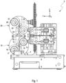
- the figure shows a machine tool designated overall by the reference numeral 2.
- the machine tool 2 comprises a machine frame 4. Furthermore, the machine tool 2 comprises a first work spindle 6 and a second work spindle 8.
- the first work spindle 6 and the second work spindle 8 are arranged one above the other with respect to a vertically extending Y-axis.
- a first pivot support 10 is arranged on the machine frame 4 and is assigned to the first work spindle 6.
- the first pivot support 10 is pivotably mounted in the machine frame 4 about a first pivot support axis 12.
- a first workpiece table 14 and a second workpiece table 16 are arranged on the first pivot support 10.
- the first workpiece table 14 and the second workpiece table 16 are arranged on opposite sides of the first pivot support 10 with respect to the pivot support axis 12.
- Figure 1 An embodiment of the machine tool 2, in which a second pivot support 20 is arranged on the machine frame 4 and is pivotably mounted about a second pivot support axis 22 running parallel to the first pivot support axis 12.
- a first workpiece table 24 and a second workpiece table 26 are arranged on the second pivot support 20.
- the first workpiece table 24 and the second workpiece table 26 are arranged on opposite sides of the second pivot support 20 with respect to the second pivot support axis 22.
- the first pivoting support 10 and the second pivoting support 20 can each be transferred from a first pivoting position, in which the respective first workpiece tables 14, 24 are arranged in a working area 28, into a second pivoting position, in which the respective second workpiece tables 16, 26 are arranged in the working area 28.
- first workpiece tables 14, 24 are arranged in the working area 28, Figure 1
- the second workpiece tables 16, 26 are arranged in a loading area 30.
- Workpieces for machining by the first work spindle 6 and/or the second work spindle 8 can be fixed to the first work tables 14, 24 and second work tables 16, 26.
- first workpiece tables 14, 24 are pivotably mounted on the respective pivot supports 10, 20 about a first workpiece axis 15, 25.
- the second workpiece tables 16, 26 are each pivotably mounted on second workpiece table axes 17, 27.
- Figure 1 shows an embodiment of the workpiece machine 2, in which the first swivel support axis 12, the second swivel support axis 22, the first workpiece axes 15, 25 and the second workpiece table axes 17, 27 run parallel to a horizontally extending X-axis.
- first workpiece axis 15 is offset from the second workpiece axis 17 with respect to a Y-axis running parallel to the vertical axis.
- first workpiece table axis 25 is offset from the second workpiece table axis 27.
- first pivot support 10 and the second pivot support 20 are arranged on the machine frame 4 such that their first pivot support axis 12 and their second pivot support axis 22 are arranged one above the other with respect to a vertically extending Y-axis and are both aligned with each other.
- the first pivot support 10 and the second pivot support 20 continue one another with respect to the vertically extending Y-axis.
- Figure 1 an interlaced arrangement of the workpiece tables 14, 24 on the respective swivel support 10, 20, whereby the distance between the work spindles 6, 8 and the respective swivel support axis 12, 22 is reduced.
- the first workpiece table 14, 24 and the second workpiece table 16, 26 of a pivoting support 10, 20 are each arranged point-symmetrically to one another with respect to the associated pivoting support axis 12, 22 of the respective pivoting support 10, 20 on which they are arranged, and in the illustrated horizontal course of the respective pivoting support axis 12, 22, the pivoting areas of the first workpiece table 14, 24 and the second workpiece table 16, 26 of the associated pivoting support 10, 20 are not maximally spaced apart with respect to a vertical plane running through the pivoting support axis 12, 22, but are moved towards one another with respect to the maximum distance, and the first workpiece table 14, 24 and the second workpiece table 16, 26 are arranged offset from one another with respect to the vertical axis.
- the first pivot support 10 comprises a first partition wall 32, by which the first workpiece table 14 is spatially separated from the second workpiece table 16.
- the second pivot support 20 comprises a second partition wall 34, by which the first workpiece table 24 is spatially separated from the second workpiece table 26.
Landscapes
- Engineering & Computer Science (AREA)
- Mechanical Engineering (AREA)
- Machine Tool Units (AREA)
Priority Applications (3)
| Application Number | Priority Date | Filing Date | Title |
|---|---|---|---|
| EP23209906.9A EP4556161A1 (fr) | 2023-11-14 | 2023-11-14 | Machine-outil |
| US18/945,023 US20250153294A1 (en) | 2023-11-14 | 2024-11-12 | Machine tool |
| CN202411622683.4A CN120002471A (zh) | 2023-11-14 | 2024-11-14 | 机床 |
Applications Claiming Priority (1)
| Application Number | Priority Date | Filing Date | Title |
|---|---|---|---|
| EP23209906.9A EP4556161A1 (fr) | 2023-11-14 | 2023-11-14 | Machine-outil |
Publications (1)
| Publication Number | Publication Date |
|---|---|
| EP4556161A1 true EP4556161A1 (fr) | 2025-05-21 |
Family
ID=88833792
Family Applications (1)
| Application Number | Title | Priority Date | Filing Date |
|---|---|---|---|
| EP23209906.9A Pending EP4556161A1 (fr) | 2023-11-14 | 2023-11-14 | Machine-outil |
Country Status (3)
| Country | Link |
|---|---|
| US (1) | US20250153294A1 (fr) |
| EP (1) | EP4556161A1 (fr) |
| CN (1) | CN120002471A (fr) |
Citations (8)
| Publication number | Priority date | Publication date | Assignee | Title |
|---|---|---|---|---|
| EP0313872A1 (fr) * | 1987-10-14 | 1989-05-03 | Chiron-Werke GmbH & Co. KG | Machine-outil |
| EP0613755A1 (fr) * | 1993-02-27 | 1994-09-07 | Chiron-Werke GmbH & Co. KG | Machine-outil |
| US5658105A (en) * | 1994-10-07 | 1997-08-19 | Brother Kogyo Kabushiki Kaisha | Splash guard for machine tool |
| DE19907617A1 (de) * | 1999-02-23 | 2000-08-31 | Schwaebische Werkzeugmaschinen | Werkzeugmaschine mit Doppelschwenktisch |
| DE10119175A1 (de) * | 2001-04-10 | 2002-10-17 | Heller Geb Gmbh Maschf | Vorrichtung zur Bearbeitung von Werkstücken sowie Verfahren zur Bearbeitung von Werkstücken unter Verwendung einer solchen Vorrichtung |
| EP1575737B1 (fr) * | 2002-12-16 | 2006-05-31 | Alfing Kessler Sondermaschinen GmbH | Machine-outil pourvue d'un module de remplacement de palettes |
| EP2431126A1 (fr) * | 2010-09-16 | 2012-03-21 | Sistech s.r.l. | Machine-outil pour enlèvement de copeaux |
| DE102017122439A1 (de) * | 2016-10-04 | 2018-04-05 | Comau France Sas | Werkzeugmaschine mit vertikaler Spindel |
-
2023
- 2023-11-14 EP EP23209906.9A patent/EP4556161A1/fr active Pending
-
2024
- 2024-11-12 US US18/945,023 patent/US20250153294A1/en active Pending
- 2024-11-14 CN CN202411622683.4A patent/CN120002471A/zh active Pending
Patent Citations (8)
| Publication number | Priority date | Publication date | Assignee | Title |
|---|---|---|---|---|
| EP0313872A1 (fr) * | 1987-10-14 | 1989-05-03 | Chiron-Werke GmbH & Co. KG | Machine-outil |
| EP0613755A1 (fr) * | 1993-02-27 | 1994-09-07 | Chiron-Werke GmbH & Co. KG | Machine-outil |
| US5658105A (en) * | 1994-10-07 | 1997-08-19 | Brother Kogyo Kabushiki Kaisha | Splash guard for machine tool |
| DE19907617A1 (de) * | 1999-02-23 | 2000-08-31 | Schwaebische Werkzeugmaschinen | Werkzeugmaschine mit Doppelschwenktisch |
| DE10119175A1 (de) * | 2001-04-10 | 2002-10-17 | Heller Geb Gmbh Maschf | Vorrichtung zur Bearbeitung von Werkstücken sowie Verfahren zur Bearbeitung von Werkstücken unter Verwendung einer solchen Vorrichtung |
| EP1575737B1 (fr) * | 2002-12-16 | 2006-05-31 | Alfing Kessler Sondermaschinen GmbH | Machine-outil pourvue d'un module de remplacement de palettes |
| EP2431126A1 (fr) * | 2010-09-16 | 2012-03-21 | Sistech s.r.l. | Machine-outil pour enlèvement de copeaux |
| DE102017122439A1 (de) * | 2016-10-04 | 2018-04-05 | Comau France Sas | Werkzeugmaschine mit vertikaler Spindel |
Also Published As
| Publication number | Publication date |
|---|---|
| CN120002471A (zh) | 2025-05-16 |
| US20250153294A1 (en) | 2025-05-15 |
Similar Documents
| Publication | Publication Date | Title |
|---|---|---|
| DE3035451C2 (fr) | ||
| DE19723702B4 (de) | CNC-Dreh- und Fräsbearbeitungszentrum | |
| EP2714307B1 (fr) | Machine-outil | |
| EP1188511B1 (fr) | Machine-outil avec un chariot porte-outil motorisé | |
| DE102004010984B3 (de) | Werkzeugmaschine zur spanenden Bearbeitung eines Werkstücks | |
| DE60303672T2 (de) | Werkzeugmaschine | |
| EP2714308B1 (fr) | Machine-outil | |
| WO2012163701A1 (fr) | Machine-outil | |
| WO2012163697A1 (fr) | Porte-outils et machine-outil pourvue dudit porte-outils | |
| EP1058593B1 (fr) | Installation d'usinage hexapode | |
| DE19907617C2 (de) | Werkzeugmaschine mit Doppelschwenktisch | |
| EP1990160A2 (fr) | Foreuse avec alimentation en continu | |
| DE19800034C2 (de) | Werkzeugmaschine für Bearbeitungswerkzeuge aus der Gruppe Schleifkörper und Fräser | |
| EP2123379B1 (fr) | Fraiseuse et tour | |
| DE102004044186A1 (de) | Bearbeitungszentrum | |
| DE60034003T2 (de) | Bohr-Fräs-Werkzeugmaschine zum Bearbeiten von Platten, oder dgl. | |
| EP4556161A1 (fr) | Machine-outil | |
| DE3750883T2 (de) | Bearbeitungsgerät. | |
| EP4559618A1 (fr) | Machine-outil et procédé d'utilisation d'une telle machine-outil | |
| EP1291101B1 (fr) | Machine-outil avec broche porte-pièce et porte-outil multiple | |
| DE102015107257A1 (de) | Bearbeitungsmaschine mit Werkzeugübergabevorrichtung | |
| EP1759815B1 (fr) | Agencement de robot comprenant un robot placé sur un bâti | |
| DE102016119464B4 (de) | Werkzeug und Werkzeugmaschine sowie Verfahren zur Bearbeitung von plattenförmigen Werkstücken | |
| EP1518638B1 (fr) | Machine-outil avec réduction de bruit active | |
| EP4588611A1 (fr) | Machine-outil |
Legal Events
| Date | Code | Title | Description |
|---|---|---|---|
| STAA | Information on the status of an ep patent application or granted ep patent |
Free format text: STATUS: EXAMINATION IS IN PROGRESS |
|
| PUAI | Public reference made under article 153(3) epc to a published international application that has entered the european phase |
Free format text: ORIGINAL CODE: 0009012 |
|
| 17P | Request for examination filed |
Effective date: 20231114 |
|
| AK | Designated contracting states |
Kind code of ref document: A1 Designated state(s): AL AT BE BG CH CY CZ DE DK EE ES FI FR GB GR HR HU IE IS IT LI LT LU LV MC ME MK MT NL NO PL PT RO RS SE SI SK SM TR |