EP4556162A2 - Procédé de polissage de lentilles - Google Patents
Procédé de polissage de lentilles Download PDFInfo
- Publication number
- EP4556162A2 EP4556162A2 EP25169064.0A EP25169064A EP4556162A2 EP 4556162 A2 EP4556162 A2 EP 4556162A2 EP 25169064 A EP25169064 A EP 25169064A EP 4556162 A2 EP4556162 A2 EP 4556162A2
- Authority
- EP
- European Patent Office
- Prior art keywords
- polishing
- tool
- workpiece
- contact surface
- use according
- Prior art date
- Legal status (The legal status is an assumption and is not a legal conclusion. Google has not performed a legal analysis and makes no representation as to the accuracy of the status listed.)
- Pending
Links
Images

Classifications
-
- B—PERFORMING OPERATIONS; TRANSPORTING
- B24—GRINDING; POLISHING
- B24B—MACHINES, DEVICES, OR PROCESSES FOR GRINDING OR POLISHING; DRESSING OR CONDITIONING OF ABRADING SURFACES; FEEDING OF GRINDING, POLISHING, OR LAPPING AGENTS
- B24B13/00—Machines or devices designed for grinding or polishing optical surfaces on lenses or surfaces of similar shape on other work; Accessories therefor
- B24B13/01—Specific tools, e.g. bowl-like; Production, dressing or fastening of these tools
-
- B—PERFORMING OPERATIONS; TRANSPORTING
- B24—GRINDING; POLISHING
- B24B—MACHINES, DEVICES, OR PROCESSES FOR GRINDING OR POLISHING; DRESSING OR CONDITIONING OF ABRADING SURFACES; FEEDING OF GRINDING, POLISHING, OR LAPPING AGENTS
- B24B13/00—Machines or devices designed for grinding or polishing optical surfaces on lenses or surfaces of similar shape on other work; Accessories therefor
- B24B13/01—Specific tools, e.g. bowl-like; Production, dressing or fastening of these tools
- B24B13/012—Specific tools, e.g. bowl-like; Production, dressing or fastening of these tools conformable in shape to the optical surface, e.g. by fluid pressure acting on an elastic membrane
-
- B—PERFORMING OPERATIONS; TRANSPORTING
- B24—GRINDING; POLISHING
- B24B—MACHINES, DEVICES, OR PROCESSES FOR GRINDING OR POLISHING; DRESSING OR CONDITIONING OF ABRADING SURFACES; FEEDING OF GRINDING, POLISHING, OR LAPPING AGENTS
- B24B13/00—Machines or devices designed for grinding or polishing optical surfaces on lenses or surfaces of similar shape on other work; Accessories therefor
- B24B13/02—Machines or devices designed for grinding or polishing optical surfaces on lenses or surfaces of similar shape on other work; Accessories therefor by means of tools with abrading surfaces corresponding in shape with the lenses to be made
-
- B—PERFORMING OPERATIONS; TRANSPORTING
- B24—GRINDING; POLISHING
- B24B—MACHINES, DEVICES, OR PROCESSES FOR GRINDING OR POLISHING; DRESSING OR CONDITIONING OF ABRADING SURFACES; FEEDING OF GRINDING, POLISHING, OR LAPPING AGENTS
- B24B9/00—Machines or devices designed for grinding edges or bevels on work or for removing burrs; Accessories therefor
- B24B9/02—Machines or devices designed for grinding edges or bevels on work or for removing burrs; Accessories therefor characterised by a special design with respect to properties of materials specific to articles to be ground
- B24B9/06—Machines or devices designed for grinding edges or bevels on work or for removing burrs; Accessories therefor characterised by a special design with respect to properties of materials specific to articles to be ground of non-metallic inorganic material, e.g. stone, ceramics, porcelain
- B24B9/08—Machines or devices designed for grinding edges or bevels on work or for removing burrs; Accessories therefor characterised by a special design with respect to properties of materials specific to articles to be ground of non-metallic inorganic material, e.g. stone, ceramics, porcelain of glass
- B24B9/14—Machines or devices designed for grinding edges or bevels on work or for removing burrs; Accessories therefor characterised by a special design with respect to properties of materials specific to articles to be ground of non-metallic inorganic material, e.g. stone, ceramics, porcelain of glass of optical work, e.g. lenses, prisms
-
- B—PERFORMING OPERATIONS; TRANSPORTING
- B24—GRINDING; POLISHING
- B24B—MACHINES, DEVICES, OR PROCESSES FOR GRINDING OR POLISHING; DRESSING OR CONDITIONING OF ABRADING SURFACES; FEEDING OF GRINDING, POLISHING, OR LAPPING AGENTS
- B24B13/00—Machines or devices designed for grinding or polishing optical surfaces on lenses or surfaces of similar shape on other work; Accessories therefor
- B24B13/06—Machines or devices designed for grinding or polishing optical surfaces on lenses or surfaces of similar shape on other work; Accessories therefor grinding of lenses, the tool or work being controlled by information-carrying means, e.g. patterns, punched tapes, magnetic tapes
Definitions
- the present invention relates to a tool according to the preamble of claim 1, a device according to the preamble of claim 8 and a method according to the preamble of claim 15 as well as a use of the tool, in each case for in particular only zonal polishing of optical workpieces, in particular lenses.
- the present invention is particularly concerned with the zonal polishing of optical workpieces.
- the tool (polishing tool) has a polishing surface that is or can be applied only partially to the workpiece to be polished in the region of a contact surface.
- This contact surface is significantly smaller than the surface of the workpiece to be polished, in particular compared to the radial extent of the workpiece.
- “Zonal,” in the sense of the present invention is understood to mean, in particular, polishing with such a "small” contact surface.
- so-called cup tools extend with their contact surface or contact edge over the entire radius of a workpiece surface to be polished.
- mushroom-shaped polishing tools are used in particular, with a curved head of the tool carrying a flexible or elastic polishing element to form a curved polishing surface.
- EP 1 796 872 B1 shows such a tool, for example.
- the polishing surface of the tool partially rests on the workpiece in the area of its contact surface, whereby the tilt angle between the surface normal of the contact surface and the rotational axis of the tool is continuously changed, so that the contact surface on the tool moves along a longitude.
- Zonal polishing is used primarily for precision optics or workpieces with aspherical surfaces, such as mirrors or lenses, and especially for correcting manufacturing errors. Accordingly, it is important to enable the most precise and defined processing possible. Polishing always involves a certain amount of material removal from the workpiece.
- the DE 10 2004 047 563 A1 discloses a method for polishing a rotating workpiece using a tool comprising a rubber membrane or a ram with a glued-on polyurethane membrane. The exact construction of the tool is not discussed in detail.
- the present invention is based on the object of specifying a tool, a device and a method as well as a use for the particularly zonal polishing of optical workpieces, whereby a particularly precise or defined polishing of the respective workpiece, in particular also of an aspherical surface, is made possible with a preferably simple structure.
- the tool has an elastic cap for forming a polishing surface or a polishing coating, preferably wherein the cap is pre-formed or shaped to adapt to the curvature of a curved head of the tool and/or sits or is stress-free on the head.
- the cap is pre-formed or shaped to adapt to the curvature of a curved head of the tool and/or sits or is stress-free on the head.
- the pre-forming or shaping before attaching or gluing the cap to the tool head can prevent or at least minimize deformations, stresses and the like in the cap material that otherwise occur during adaptation to the curvature, which are usually undefined.
- the cap has a multi-layer structure and, in particular, comprises an intermediate element and a polishing element. This is conducive to achieving the desired properties, particularly with regard to spring behavior, abrasion behavior, and polishing behavior.
- the polishing element forms a polishing coating or a polishing film or polishing layer.
- the polishing surface or the polishing coating formed by the cap or the polishing element generally forms a polishing agent carrier for a polishing agent.
- the proposed polishing refers to polishing with a polishing agent, which is present or used in particular in the form of a suspension with polishing particles, such as very fine grains, particles, or the like.
- the polishing surface also serves, in particular, to transport the polishing agent into an active gap between the contact surface of the tool and the surface to be polished and/or to distribute or move it therein and/or to rub the polishing agent against the surface.
- polishing reduces surface roughness and/or can remove cracks in the material that occurred during previous shaping, for example, through grinding. Material is removed in each process. The removed material is transported by the tool or polishing surface, also by means of the polishing agent, out of the effective gap between the polishing surface and the surface to be polished.
- the present invention relates in particular to the polishing of a workpiece using a tool and a polishing agent.
- polishing can alternatively be performed without a separate or additional polishing agent, but solely with the tool.
- the polishing surface can be either porous or non-porous and/or provided with a favorable surface structure or texture in order to achieve the desired polishing effect, particularly with a specific polishing agent for the respective workpiece material.
- the intermediate element and the polishing element are pre-shaped or machined to adapt to the curvature.
- the polishing element is then adapted to the shape of the intermediate element through prior shaping. This also allows stresses between the two elements to be avoided or at least minimized.
- Pre-forming can be done, for example, by appropriate foaming or other primary forming with the desired shape.
- the shaping is preferably carried out by material removal or mechanical machining of the cap or the elements forming the cap, in particular by milling and/or turning, for example from plate or solid material.
- the polishing element is preferably substantially thinner than the intermediate element.
- the cap or intermediate element and the polishing element are glued on. This allows for a simple assembly.
- the tool has a collar or other stop in the area of the head for circumferential support and/or positioning of the cap. This contributes to simple and defined production.
- a proposed device and a proposed method are characterized in particular by the fact that the diameter of the contact surface of the tool on the workpiece and/or the tilt angle of the rotational axis of the tool to the normal (surface normal) of the contact surface is/are kept at least substantially constant during the polishing of the workpiece, i.e., during the respective polishing process. This is conducive to defined polishing with, in particular, defined material removal.
- the proposed device and the proposed method are characterized in particular by the fact that the tool is moved or can be moved from an edge of a surface of the workpiece to be polished across the center to the opposite side of the edge. This enables particularly uniform polishing, especially in the area of the visually important and sensitive center of the workpiece. The usual stopping or ending of the polishing process in the center region usually leads to uneven and/or undefined material removal.
- the indentation depth of the particularly elastically deformable polishing surface on the tool is preferably varied, controlled or regulated by appropriately advancing the tool relative to the workpiece during the polishing process, particularly preferably depending on the radial position of the contact surface on the workpiece, the desired diameter of the contact surface, the (desired) contact pressure of the tool on the workpiece, and/or the profile of the workpiece, particularly the curvature of the workpiece in the area of the respective contact surface.
- This promotes defined polishing and defined material removal, while also enabling optimization of the time required for polishing.
- the distance between adjacent tracks of the preferably spiral polishing path of the contact surface on the workpiece or the surface to be polished is optionally kept at least substantially constant. This is conducive to defined polishing or defined material removal.
- the rotational speed of the workpiece during one revolution is optionally varied or controlled or regulated depending on the rotational position, a locally desired dwell time (polishing time), the diameter of the contact surface, the contact pressure of the tool on the workpiece, and/or the profile of the workpiece, particularly in the area of the respective contact surface.
- This allows optimal polishing with defined material removal and/or influencing or controlling, even taking into account the actual three-dimensional shape of the surface to be polished.
- the tool is preferably provided with a polishing surface formed from at least substantially closed pores, in particular wherein more than 1 or 5% (based on the surface area or number of pores) of the polishing surface is formed by pores with a size of more than 0.5 mm and/or more than 25 or 50% (based on the surface area or number of pores) is formed by pores with a size of less than 0.4 or 0.3 mm, particularly preferably less than 0.1 mm, and/or in particular wherein the size of the pores on the polishing surface is less than 1 mm, in particular less than 0.9 mm, and/or in particular wherein the polishing surface is not mechanically machined or dressed.
- the size of the pores is considered to be, in particular, the mean or maximum diameter. Tests have shown that such a polishing surface exhibits particularly good polishing properties, in particular when polishing precision optics or glass.
- the polishing surface or the polishing coating or cap forming it is made of polyurethane or another suitable foam or plastic.
- the tool is used for zonal polishing or is manufactured and prepared for the polishing device, so that (further) conditioning or dressing of the polishing tool in new condition in the polishing machine, as is common in particular in precision machining, is no longer necessary.
- the workpiece to be polished is first measured and errors can then be corrected by corrective polishing using the proposed tool, the proposed device or the proposed methods.
- the proposed tool, the proposed device and/or the proposed methods can be used in particular for pre-polishing and/or corrective polishing.
- Fig. 1 shows a schematic representation of a proposed device 1 for, in particular, zonal polishing of an optical workpiece 2, in particular a lens, a mirror or the like, particularly preferably made of glass.
- the device 1 is designed for polishing the workpiece 2 by means of a tool 3, in particular according to the proposal, or another tool.
- a tool 3 in particular according to the proposal, or another tool.
- the preferred structure of the proposed polishing tool 3 is described in particular with reference to Fig. 2 explained in more detail.
- Fig. 1 the tool 3 is shown together with an associated tool spindle 13 of the device 1 in three different positions, in particular to illustrate the mobility of the tool 3 or a preferred process sequence.
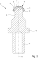
- the proposed tool 3 is shown in a schematic section in Fig. 2 It preferably comprises a carrier 4 with a curved head 5 and a particularly hemispherical or conical cap 6.
- the cap 6 is preferably constructed in several layers and, in the example shown, preferably has an intermediate element 7 and a polishing element 8.
- the tool 3, the cap 6 or its intermediate element 7 is attached to the head 5 of the tool 3, in particular glued thereto.
- the cap 6 or its polishing element 8 forms a polishing surface 9.
- the polishing surface 9 of the tool 3 or the cap 6 or the element 8 is preferably convexly curved, in particular geometrically similar to the head 5 or curved to match it and/or preferably spherical or hemispherical and/or conical.
- the polishing element 8 is mounted on the intermediate element 7, in particular glued thereto.
- the cap 6 can also be formed in one piece and/or made in multiple layers by bi-injection or the like.
- the cap 6 or the intermediate element 7 and/or the polishing element 8 is/are preferably made of plastic or foam and/or of an elastic and/or flexible material.
- the intermediate element 7 is made of a preferably closed-cell foam, in particular of polyurethane.
- the cap 6 or the intermediate element 7 preferably has a static modulus of elasticity under static continuous load of more than 0.5 N/mm 2 , preferably more than 1 N/mm 2 , in particular more than 1.5 N/mm 2 , and/or less than 30 N/mm 2 , preferably less than 15 N/mm 2 , in particular less than 7.0 N/mm 2 , and/or a dynamic modulus of elasticity under a dynamic continuous load of 10 Hz of more than 0.5 N/mm 2 , preferably more than 1 N/mm 2 , in particular more than 1.3 N/mm 2 , and/or less than 20 N/mm 2 , preferably less than 10 N/mm 2 , in particular less than 8.0 N/mm 2 , and/or a compression hardness at 10% deformation of more than 0.05 N/mm 2 , preferably more than 0.1 N/mm 2 , in particular more than 0.2 N/mm 2 , and/or less than 3 N/mm 2 , preferably less than 2 N/mm 2 , in particular less
- the polishing element 8 is preferably made of a harder and/or stiffer material than the intermediate element 7.
- the polishing element 8 is preferably thin-walled and/or foil-like.
- the density - preferably according to DIN EN ISO 845:2009-10 - of the polishing element 8 is preferably more than 300 kg/m 3 , in particular more than 500 kg/m 3 , particularly preferably more than 700 kg/m 3 , and/or preferably less than 4000 kg/m 3 , in particular less than 3000 kg/m 3 , particularly preferably less than 2000 kg/m 3 .
- the polishing element 8 or the cap 6 or polishing surface 9 preferably has a Shore hardness A of more than 5, in particular more than 10, particularly preferably more than 20, and/or preferably less than 90, in particular less than 80, particularly preferably less than 70, in particular according to DIN ISO EN 868:2003-10 or DIN ISO 7619-1:2012-02.
- the polishing element 8 preferably has a thickness of more than 0.1 mm, in particular more than 0.3 mm, particularly preferably more than 0.4 mm, and/or preferably less than 3 mm, in particular less than 2 mm, particularly preferably less than 1 mm.
- the thickness of the intermediate element 7 is preferably more than 2 mm and/or less than 10 mm, in particular about 3 to 7 mm.
- the thickness of the intermediate element 7 is preferably at least 5 times, in particular about 10 times, the thickness of the polishing element 8 or more.
- the cap 6, the intermediate element 7 and/or the polishing element 8 preferably each have an at least substantially constant thickness.
- the polishing element 8 or the polishing surface 9 is preferably formed or manufactured from an open-cell or closed-cell plastic or composite material or the like.
- the polishing element 8 is preferably made of a plastic film or polyurethane.
- the cap 6 or the intermediate element 7 and/or polishing element 8 is/are preferably pre-shaped or machined internally and/or externally to adapt its shape to the curvature of the head 5 and/or to achieve a desired curvature or other shape, such as a sphere, i.e., before being attached to the tool 3 or head 5, its shape is adapted to that of the head 5, in particular provided with a complementary curvature to the head 5 or intermediate element 7.
- the tool 3 or the head 5 preferably forms a solid or non-yielding surface made of metal or another suitable material for supporting and in particular also fastening the cap 6 or elements 7, 8 arranged thereon.
- the shaping or shaping of the cap 6 or the intermediate element 7 and/or polishing element 8 is particularly preferably carried out mechanically, in particular by turning and/or milling.
- Solid material is particularly preferably machined to achieve the desired shape.
- Mechanical processing has the advantage that a very uniform material layer can be produced without material compression, deformation or other material irregularities with the desired shape, here in particular a cap-like or spherical shape, or possibly also another shape.
- the aforementioned shaping can also be carried out, for example, by appropriate foaming or other primary shaping.
- the preformed or shaped cap 6 or correspondingly preformed or shaped elements 7 and 8 is/are attached to the tool 3 or head 5, in particular by gluing.
- the polishing element 8 is attached to the intermediate element 7 by gluing.
- it can also be connected in other ways.
- the cap 6 or the intermediate element 7 is or sits on the head 5 without tension.
- stress-free is to be understood in particular as meaning that, in the applied state, no local material deformations or stresses occur in the material of the cap 6 or elements 7, 8 due to adaptation to the curvature, which would arise during the deformation to adapt to the curved shape and which (can) negatively influence a uniform and in particular defined spring and damping behavior of the cap 6 or elements 7, 8.
- the polishing element 8 should also be mounted tension-free in this sense, in particular in order to avoid any possible formation of wrinkles.
- the polishing element 8 is adapted to the curvature of the outer side of the intermediate element 7 by appropriate pre-forming, in particular shaping, before being attached to or connected to the intermediate element 7.
- the tool 3 or the cap 6 or the polishing element 8 or the polishing surface 9 is designed in particular such that a polishing agent (not shown) is transported over the polishing surface 9 and as a result the workpiece 2 can be machined and polished in a mechanical-chemical removal process, as already described at the beginning.
- the tool 3 or its carrier 4 preferably has a collar 10 or other stop, which in particular projects laterally from the head 5 and/or forms a preferably circumferential shoulder or the like.
- the tool 3 or the carrier 4 preferably has a connecting section 11 and/or a stop 12 for the defined fastening or holding of the tool 3 on the associated tool spindle 13 or its tool chuck 14 or the like.
- the tool 3 is clamped or fastened to the tool spindle 13 by means of the tool chuck 14.
- the stop 12 serves in particular to define a defined axial position of the tool 3 on the tool spindle 13 or on the tool chuck 14.
- other design solutions are also possible.
- tools 3 with different curvature radii of the head 5 or the cap 6 or the polishing surface 9 are used depending on the shape of the surface 2A to be polished.
- the radius of curvature of the polishing surface 9 is preferably more than 2 mm, in particular more than 3 mm or 5 mm, and/or preferably less than 1000 mm, in particular less than 500 mm, particularly preferably less than 100 mm, preferably depending on the (maximum) curvature of the surface 2A to be polished and/or the desired application.
- tools 3 with smaller radii of curvature, preferably less than 100 mm, are used.
- the distance of the polishing surface 9, in particular at the intersection point with the rotation axis R, to the stop 12 is preferably the same for all tools 3, even if they have different curvatures or curvatures.
- the proposed device 1 has the tool spindle 13 for rotating the associated or clamped tool 3 about a rotation axis R, as shown in Fig. 1 indicated.
- the rotation speed is preferably about 1000 to 5000 revolutions per minute.
- the rotation speed is preferably controlled or regulated.
- the rotation speed is kept constant during the polishing process.
- the rotation of tool 3 preferably occurs without detecting the angle of rotation. Therefore, it is not a controlled rotation axis in the sense of a CNC control.
- the tool spindle 13 and thus the tool 3 can be pivoted about a pivot axis B.
- this is a controlled or regulated pivot axis or CNC axis, also called a rotary axis.
- the pivot position is recorded. This enables defined pivoting, as exemplified by the three different positions in Fig. 1 shown.
- the pivot axis B runs transversely and in particular perpendicular to the rotation axis R or the plane of the drawing.
- the pivot axis B is preferably arranged as close as possible to the tool 3 or to the polishing surface 9 and/or to the tool chuck 14.
- the device 1 has a workpiece drive 15, in particular a workpiece spindle, for the workpiece 2, so that the workpiece 2 to be polished can be rotated about the rotation axis C with a defined angular position.
- the workpiece 2 is held or coupled to the workpiece drive 15 at a defined angular position by means of a holder 16, such as a block piece, and/or by means of a chuck.
- a holder 16 such as a block piece
- the rotation axis C is, in particular, a controlled or regulated axis or a CNC axis, also called a rotary axis.
- the rotation angle position is also detected here.
- an angle-dependent variation of the rotation speed is enabled, even within one revolution.
- the rotational speed of the workpiece drive 15 or of the workpiece 2 is generally variable, in particular, for example, from approximately 10 or 20 revolutions per minute (for polishing at the edge 2C of the side 2A of the workpiece 2 to be polished) up to approximately 2000 to 3000 revolutions per minute (for polishing in the area of the center 2B of the workpiece 2).
- the C-axis preferably runs in a plane with the rotation axis R (independent of the pivoting position of the tool spindle 13) and/or transversely or perpendicularly to the pivoting axis B.
- the workpiece drive 15 and thus the workpiece 2 are preferably linearly movable or adjustable in the Z-direction, as in Fig. 1 indicated.
- the adjustment is carried out in particular by means of a slide and adjustment drive (not shown) or the like.
- the Z-axis preferably runs parallel to the C-axis and/or transversely or perpendicularly to the swivel axis B.
- the tool spindle 13 and thus the tool 3 are preferably adjustable transversely in the X-direction, in particular by means of a carriage (not shown) and an associated drive.
- This carriage then preferably also carries the B-axis and the corresponding pivot drive for pivoting the tool spindle 13.
- the X-axis and Z-axis are preferably designed as controlled or regulated axes or as CNC axes or linear axes, so that precise positioning in the X and Z directions is possible.
- the X-axis preferably runs transversely or perpendicularly to the C-axis, B-axis and/or Z-axis.
- the X-axis preferably runs in or parallel to the common plane of the C-axis and R-axis.
- the axes can also be stacked or distributed differently.
- the Z-axis can be assigned to the tool spindle 13 instead of the workpiece drive 15.
- the B-axis and/or X-axis can be implemented on the workpiece side rather than on the tool side.
- the device 1 is in particular a polishing machine or CNC machine with X, Z, B and C axes.
- the X-axis and/or the B-axis run horizontally.
- the C-axis and/or the Z-axis runs vertically.
- the polishing tools 3 are each located with their polishing surfaces 9 at the level of or near the B-axis, so that the contact surface A can be pivoted with as little radius as possible.
- the B-axis is preferably spaced less than 100 or 50 mm, in particular less than 30 or 15 mm, particularly preferably less than 10 mm from the polishing surface 9 or contact surface A, in particular from the intersection point of the rotation axis R with the polishing surface 9. In particular, this distance is preferably at least substantially the same even for tools 3 with different radii of curvature of the polishing surface 9.
- the B-axis intersects the rotation axis R preferably within the cap 6 or polishing surface 9.
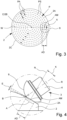
- the tool 3 can be moved in particular as indicated by arrow W in Fig. 1 and in Fig. 3 schematically indicated over the workpiece 2 or the surface 2A to be polished.
- the tool 3 is moved from an edge 2C of the workpiece 2 or the surface 2A towards the center 2B and beyond this to the opposite side of the edge 2C, as in Fig. 1 and 3 This avoids interrupting or terminating the polishing process in the center 2B area, as is common in the prior art, and thus enables or ensures more optimal processing or more defined material removal.
- the polishing surface 9 of the tool 3 only partially rests with a contact surface A on the workpiece 2 to be polished or its surface 2A, as is particularly shown in Fig. 4 schematically shown, which is a partial enlargement of the dotted circle area of Fig. 1 represents.
- the contact surface A is preferably at least substantially circular, whereby this (also) depends on the three-dimensional shape of the surface 2A.
- the contact surface A, with which the polishing surface 9 rests on the workpiece 2 or its surface 2A, is also indicated.
- the surface normal N intersects the rotation axis R of the tool 3 at a (relative) tilt angle K, as in Fig. 1 and 4 indicated.
- polishing with the tool 3 is carried out in such a way that the contact surface A lies off-center with respect to the rotation axis R on the polishing surface 9.
- work or polishing is carried out (preferably always) with a tilt angle K of more than 0°, in particular more than 2°, particularly preferably more than 5° or 10°, and/or preferably less than 50°, in particular less than 30°, particularly preferably less than 25°.
- the tilt angle K is kept constant during the respective polishing process. This is achieved by appropriately pivoting the tool spindle 13 or the tool 3.
- the pivot angle S (angle of the rotation axis R to the C-axis) then varies accordingly along the tool path W, as shown schematically in Fig. 1 indicated, for example, by a small swivel angle S in the left position via a medium swivel angle S in the middle position to a large swivel angle S in the right position.
- a polishing process in the sense of the present invention refers in particular to the complete polishing of the surface 2A of the workpiece 2 to be polished with a tool 3.
- the tool path W is preferably traversed or followed by the tool 3 while, on the one hand, the tool 3 and, on the other hand, the workpiece 2 rotate.
- the contact surface A or its center AM then sweeps over the surface 2A to be polished in a particularly spiral-shaped polishing path P, as in Fig. 3
- the spiral polishing path P is traversed once when the tool 3 or the contact surface A moves from the edge region 2C to the center 2B or to the rotation axis C.
- the same or a corresponding spiral polishing path P is then traversed again when the tool 3 or the contact surface A continues to move outwards from the center 2B to the edge region 2B, following the tool path W.
- the device 1 is designed in such a way or a control or regulation is carried out in such a way that a uniform spiral or an at least substantially constant distance PA between adjacent polishing tracks PS of the polishing path P is achieved or traversed, as in Fig. 3
- the distance PA is therefore particularly preferably kept at least substantially constant.
- the distance PA can alternatively vary, particularly depending on the workpiece radius at which the center of the contact surface is (straight) located.
- the diameter AD of the contact surface A is at least 10 or 20 times larger than the spiral spacing or spacing PA of adjacent polishing tracks PS.
- the tool 3 rotates opposite to the workpiece 2.
- rotation in the same direction is also possible.
- tool 3 rotates (much) faster than workpiece 2.
- the rotational speed of the workpiece 2 and thus also the movement speed of the workpiece 2 along the tool path W are increased starting from the edge 2C to the center 2B and then reduced again towards the edge, while the rotational speed of the tool 3 remains constant.
- the rotational speed of the workpiece 2 can also be varied during one revolution, in particular depending on the rotational position, the diameter AD of the contact surface A, the contact pressure of the tool 3 on the workpiece 2, the indentation depth E of the polishing surface 9, and/or the profile of the workpiece 2, in order to achieve particularly uniform material removal or a desired polishing result. This allows, in particular, highly precise polishing.
- the device 1 is designed in such a way, or the proposed method is implemented in such a way, that the size or diameter AD of the contact surface A is kept at least substantially constant during the polishing process. This promotes uniform and defined material removal.
- the size or diameter AD of the contact surface A is also determined in particular by the Fig. 4
- the schematically indicated indentation depth E of the polishing surface 9 is determined by appropriate infeed of the tool 3 during the polishing process, but also depends on the surface shape of the workpiece 2, in particular the respective curvature conditions and the curvature of the polishing surface 9.
- the indentation depth E of the polishing surface 9 and thus also the size or diameter AD of the contact surface A are varied accordingly.
- the indentation depth E of the polishing surface 9 is varied by appropriately advancing the tool 3 during a polishing process in such a way that, in particular even with different curvatures of the surface 2A to be polished, particularly preferably with an aspherical surface 2A, an at least substantially constant diameter AD of the contact surface A is achieved. This contributes to uniform and defined material removal throughout the entire polishing process.
- the diameter AD of the contact surface A decreases from the edge 2C to the center 2B and increases in the opposite direction.
- the speed of the C-axis i.e. the rotational speed of the workpiece 2 is preferably derived from calculated dwell times of the contact surface A over certain partial areas of the surface 2A to be polished.
- the path speed or rotational speed of the workpiece 2 is preferably changed within one revolution. This allows different polishing or dwell times to be realized, particularly within one revolution, depending on the required error correction.
- the speed of the X-axis is adjusted so that the desired constant spiral pitch PA or spacing between adjacent polishing tracks PS remains constant per revolution. Accordingly, the feed in the X-direction is directly coupled to the speed or number of revolutions of the C-axis, or vice versa.
- the optimal dwell time of the tool 3 or the contact surface A is determined in advance by means of a simulation in local areas on the surface 2A to be polished. Subsequently, the corresponding path positions and path speeds are determined from the calculated local dwell times.
- the optimal indentation depth E of the polishing surface 9 or the infeed of the tool 3 on the workpiece 2 is optimally determined depending on the tool 3 and the geometry of the surface 2 to be polished, in particular by means of corresponding calculations, estimates and/or measurements, wherein the indentation depth E is adjusted during the polishing process in particular so that the diameter AD of the contact surface A remains as constant as possible.
- the proposed polishing tool 3 is characterized in particular by a cap 6 or a cap structure with defined spring and damping properties
- the size of the contact surface A can be influenced very precisely by the indentation depth E.
- the indentation depth E is preferably more than 0.1 mm and/or less than 0.8 mm.
- the size or diameter AD of the contact surface A is preferably more than 1 mm, in particular more than 3 mm, and/or less than 25 mm, in particular less than 15 or 10 mm.
- zonal polishing of the workpiece 2 is carried out.
- “Zonal” is to be understood as meaning that the contact surface A is significantly smaller than the surface 2A of the workpiece 2 to be polished, in particular compared to the radial extent of the workpiece 2.
- the mean or largest diameter AD of the contact surface A is significantly smaller than the mean or largest radius of the workpiece 2.
- the mean or largest radius of the workpiece 2 is at least a factor of 2, 3 or 5 larger than the mean or largest diameter AD of the contact surface A.
- the device 1 also has a feed for polishing agent (not shown), as is usual in polishing machines, so that the polishing agent can be fed in the desired manner during polishing.
- the proposed tool 3, the proposed device 1, and/or the proposed method can be used in particular for polishing precision optics or aspherical surfaces or other optical workpieces, wherein the surface shape can preferably be measured before polishing, allowing a desired surface shape to be achieved by polishing. This is also referred to as corrective polishing.
- polishing can be carried out with an accuracy of 10 to 100 nm.
- Tools 3 with smaller radii of curvature of the polishing surface 9, in particular with radii of curvature of less than 100 mm, particularly preferably less than 50 mm, are preferably used for correction purposes.
- Tools 3 with larger radii of curvature of the polishing surface 9, in particular up to 1000 mm, are preferably used for pre-polishing.
- the surface to be machined 2A is preferably measured and then corrective polishing is carried out.
- the proposed device 1 and the proposed methods can in principle be used for both pre-polishing and corrective polishing.
Landscapes
- Engineering & Computer Science (AREA)
- Mechanical Engineering (AREA)
- Physics & Mathematics (AREA)
- Fluid Mechanics (AREA)
- Chemical & Material Sciences (AREA)
- Ceramic Engineering (AREA)
- Inorganic Chemistry (AREA)
- Grinding And Polishing Of Tertiary Curved Surfaces And Surfaces With Complex Shapes (AREA)
- Finish Polishing, Edge Sharpening, And Grinding By Specific Grinding Devices (AREA)
Applications Claiming Priority (3)
| Application Number | Priority Date | Filing Date | Title |
|---|---|---|---|
| DE102016006741.1A DE102016006741A1 (de) | 2016-06-06 | 2016-06-06 | Werkzeug, Vorrichtung und Verfahren zum Polieren von Linsen |
| PCT/EP2017/025160 WO2017211467A1 (fr) | 2016-06-06 | 2017-06-02 | Outil, dispositif et procédé de polissage de lentilles |
| EP17729015.2A EP3463751B1 (fr) | 2016-06-06 | 2017-06-02 | Procédé de polissage de lentilles |
Related Parent Applications (1)
| Application Number | Title | Priority Date | Filing Date |
|---|---|---|---|
| EP17729015.2A Division EP3463751B1 (fr) | 2016-06-06 | 2017-06-02 | Procédé de polissage de lentilles |
Publications (2)
| Publication Number | Publication Date |
|---|---|
| EP4556162A2 true EP4556162A2 (fr) | 2025-05-21 |
| EP4556162A3 EP4556162A3 (fr) | 2025-08-13 |
Family
ID=59034713
Family Applications (2)
| Application Number | Title | Priority Date | Filing Date |
|---|---|---|---|
| EP17729015.2A Active EP3463751B1 (fr) | 2016-06-06 | 2017-06-02 | Procédé de polissage de lentilles |
| EP25169064.0A Pending EP4556162A3 (fr) | 2016-06-06 | 2017-06-02 | Procédé de polissage de lentilles |
Family Applications Before (1)
| Application Number | Title | Priority Date | Filing Date |
|---|---|---|---|
| EP17729015.2A Active EP3463751B1 (fr) | 2016-06-06 | 2017-06-02 | Procédé de polissage de lentilles |
Country Status (5)
| Country | Link |
|---|---|
| US (1) | US11890712B2 (fr) |
| EP (2) | EP3463751B1 (fr) |
| CN (1) | CN109414795A (fr) |
| DE (1) | DE102016006741A1 (fr) |
| WO (1) | WO2017211467A1 (fr) |
Families Citing this family (10)
| Publication number | Priority date | Publication date | Assignee | Title |
|---|---|---|---|---|
| KR102526545B1 (ko) * | 2017-03-06 | 2023-04-28 | 어플라이드 머티어리얼스, 인코포레이티드 | Cmp 위치 특정 연마(lsp)를 위해 설계된 나선형 및 동심 이동 |
| DE102018202570A1 (de) | 2018-02-20 | 2019-08-22 | Carl Zeiss Smt Gmbh | Verfahren zum Polieren eines Werkstücks bei der Herstellung eines optischen Elements |
| DE102019005294A1 (de) * | 2019-01-17 | 2020-07-23 | Schneider Gmbh & Co. Kg | Polierwerkzeug und Vorrichtung zum Polieren eines Werkstücks |
| GB2582639B (en) * | 2019-03-29 | 2023-10-18 | Zeeko Innovations Ltd | Shaping apparatus, method and tool |
| DE102020007766A1 (de) * | 2020-08-07 | 2022-02-10 | Schneider Gmbh & Co. Kg | Werkzeugaufnahme, Bearbeitungswerkzeug, Werkzeugspindel sowie Verfahren zur Bearbeitung optischer Werkstücke |
| CN115609250A (zh) * | 2022-06-10 | 2023-01-17 | 眉山博雅新材料股份有限公司 | 一种模具加工方法及其系统 |
| CN115383560A (zh) * | 2022-10-31 | 2022-11-25 | 中国科学院长春光学精密机械与物理研究所 | 抛光磨头、抛光设备、光学镜片非球面模具的抛光方法 |
| EP4599965A4 (fr) * | 2022-11-25 | 2026-02-18 | Jfe Steel Corp | Système d'usinage, procédé de création de trajectoire et procédé de fabrication de produit |
| CN116984991A (zh) * | 2023-07-19 | 2023-11-03 | 天津津航技术物理研究所 | 一种柔性主动射流抛光工具 |
| CN118305690B (zh) * | 2024-06-07 | 2024-09-27 | 中国科学院光电技术研究所 | 一种非球面光学元件分区加工方法 |
Citations (2)
| Publication number | Priority date | Publication date | Assignee | Title |
|---|---|---|---|---|
| DE102004047563A1 (de) | 2004-09-30 | 2006-04-06 | Asphericon Gmbh | Verfahren zum Polieren |
| DE102009004787A1 (de) | 2009-01-13 | 2010-07-15 | Schneider Gmbh & Co. Kg | Vorrichtung und Verfahren zum Polieren von Linsen |
Family Cites Families (30)
| Publication number | Priority date | Publication date | Assignee | Title |
|---|---|---|---|---|
| US3430391A (en) * | 1962-12-31 | 1969-03-04 | Indiana Contact Lens Inc | Apparatus for altering the power of a corneal contact lens |
| US4979337A (en) * | 1986-10-03 | 1990-12-25 | Duppstadt Arthur G | Polishing tool for contact lenses and associated method |
| US4989316A (en) * | 1987-03-09 | 1991-02-05 | Gerber Scientific Products, Inc. | Method and apparatus for making prescription eyeglass lenses |
| US5320006A (en) * | 1991-09-27 | 1994-06-14 | Coburn Optical Industries, Inc. | Methods and apparatus for producing ophthalmic lenses |
| US5577950A (en) * | 1993-11-29 | 1996-11-26 | Coburn Optical Industries, Inc. | Conformal tool operating apparatus and process for an ophthalmic lens finer/polisher |
| JPH0985603A (ja) * | 1995-09-28 | 1997-03-31 | Nikon Corp | 研磨方法及び研磨装置 |
| JP2000071154A (ja) * | 1998-08-28 | 2000-03-07 | Canon Inc | 研磨工具の製作方法 |
| JP2002535151A (ja) * | 1998-12-01 | 2002-10-22 | ユニヴァーシティ カレッジ ロンドン | 研磨装置および方法 |
| AU2001237285A1 (en) * | 2000-02-03 | 2001-08-14 | Carl Zeiss | Polishing head for a polishing machine |
| EP1203626B1 (fr) * | 2000-02-16 | 2007-04-11 | Seiko Epson Corporation | Procede de fabrication de verres de lunettes, et outil de polissage |
| JP2001263101A (ja) | 2000-03-14 | 2001-09-26 | Fuji Heavy Ind Ltd | エンジンのバルブタイミング制御装置 |
| DE10031057B4 (de) | 2000-06-26 | 2005-04-07 | Optotech Optikmaschinen Gmbh | Verfahren und Vorrichtung zum korrigierenden Feinstpolieren von vorbearbeiteten optischen Linsen und Spiegeln |
| US8062098B2 (en) * | 2000-11-17 | 2011-11-22 | Duescher Wayne O | High speed flat lapping platen |
| JP2002154040A (ja) * | 2000-11-20 | 2002-05-28 | Ikegami Kanagata Kogyo Kk | 回転工具 |
| FR2823143B1 (fr) | 2001-04-10 | 2003-07-04 | Essilor Int | Outil torique de polissage d'une surface optique d'une lentille, et procede de polissage d'une surface atorique au moyen d'un tel outil |
| JP2003340698A (ja) * | 2002-05-30 | 2003-12-02 | Hoya Corp | レンズ加工装置及びレンズ加工方法 |
| US20040229553A1 (en) * | 2003-05-16 | 2004-11-18 | Bechtold Michael J. | Method, apparatus, and tools for precision polishing of lenses and lens molds |
| US7494305B2 (en) * | 2004-08-03 | 2009-02-24 | Essilor International (Compagnie Generale D'optique) | Raster cutting technology for ophthalmic lenses |
| EP1655102B1 (fr) * | 2004-11-09 | 2008-01-09 | Seiko Epson Corporation | Outil de polissage élastique et méthode de polissage d'une lentille utilisant cet outil |
| US7312154B2 (en) * | 2005-12-20 | 2007-12-25 | Corning Incorporated | Method of polishing a semiconductor-on-insulator structure |
| JP4598749B2 (ja) * | 2006-12-21 | 2010-12-15 | セイコーエプソン株式会社 | 粘着テープ及び粘着テープの貼り付け方法 |
| DE102010035526A1 (de) * | 2010-08-25 | 2012-03-01 | Fraunhofer-Gesellschaft zur Förderung der angewandten Forschung e.V. | Feinbearbeitungsmembran und -werkzeug |
| JP5864298B2 (ja) * | 2011-02-21 | 2016-02-17 | Hoya株式会社 | 眼鏡レンズの製造方法 |
| JP5809816B2 (ja) * | 2011-03-08 | 2015-11-11 | オリンパス株式会社 | レンズ研磨皿の作製方法 |
| DE102013108766B4 (de) * | 2013-08-13 | 2023-11-16 | Optotech Optikmaschinen Gmbh | Polierverfahren zur Bearbeitung einer optischen Oberfläche einer optischen Linse und hierfür geeignete Polierwerkzeuge |
| WO2015190189A1 (fr) * | 2014-06-10 | 2015-12-17 | オリンパス株式会社 | Outil de meulage, procédé de meulage et dispositif de meulage |
| DE102014015052A1 (de) * | 2014-10-15 | 2016-04-21 | Satisloh Ag | Polierteller für ein Werkzeug zur Feinbearbeitung von optisch wirksamen Flächen an Brillengläsern |
| JP6378626B2 (ja) * | 2014-12-17 | 2018-08-22 | オリンパス株式会社 | 光学素子の加工用工具および光学素子の製造方法 |
| EP3482873B1 (fr) * | 2016-07-08 | 2023-08-30 | Kojima Engineering Co., Ltd. | Procédé de traitement de surface de lentille sphérique utilisant une meule en forme de coupelle et appareil de traitement de surface de lentille sphérique |
| DE102019005084A1 (de) * | 2019-07-16 | 2021-01-21 | Schneider Gmbh & Co. Kg | Polierwerkzeug sowie Vorrichtung zum Polieren eines Werkstücks |
-
2016
- 2016-06-06 DE DE102016006741.1A patent/DE102016006741A1/de not_active Withdrawn
-
2017
- 2017-06-02 WO PCT/EP2017/025160 patent/WO2017211467A1/fr not_active Ceased
- 2017-06-02 US US16/307,174 patent/US11890712B2/en active Active
- 2017-06-02 CN CN201780042480.XA patent/CN109414795A/zh active Pending
- 2017-06-02 EP EP17729015.2A patent/EP3463751B1/fr active Active
- 2017-06-02 EP EP25169064.0A patent/EP4556162A3/fr active Pending
Patent Citations (3)
| Publication number | Priority date | Publication date | Assignee | Title |
|---|---|---|---|---|
| DE102004047563A1 (de) | 2004-09-30 | 2006-04-06 | Asphericon Gmbh | Verfahren zum Polieren |
| EP1796872B1 (fr) | 2004-09-30 | 2008-11-26 | Asphericon Gmbh | Procede pour polir, en particulier, des surfaces de faces optiquement actives, telles que des lentilles |
| DE102009004787A1 (de) | 2009-01-13 | 2010-07-15 | Schneider Gmbh & Co. Kg | Vorrichtung und Verfahren zum Polieren von Linsen |
Also Published As
| Publication number | Publication date |
|---|---|
| EP3463751B1 (fr) | 2025-05-07 |
| EP4556162A3 (fr) | 2025-08-13 |
| DE102016006741A1 (de) | 2017-12-07 |
| EP3463751A1 (fr) | 2019-04-10 |
| US20190126425A1 (en) | 2019-05-02 |
| CN109414795A (zh) | 2019-03-01 |
| WO2017211467A1 (fr) | 2017-12-14 |
| US11890712B2 (en) | 2024-02-06 |
| EP3463751C0 (fr) | 2025-05-07 |
Similar Documents
| Publication | Publication Date | Title |
|---|---|---|
| EP3463751B1 (fr) | Procédé de polissage de lentilles | |
| EP0807491B1 (fr) | Support pour lentille optique et procédé pour polir des lentilles | |
| EP1719585B1 (fr) | Machine destinée au traitement de pièces optiques, nominalement de verres de lunettes en plastique | |
| EP3206837B1 (fr) | Disque à polir pour un outil destiné au traitement précis de surfaces optiques actives en particulier sur des verres de lunettes | |
| EP1608485B1 (fr) | Procede et dispositif pour realiser des verres de lunettes et d'autres corps moules ayant des surface optiquement actives | |
| EP3463746B1 (fr) | Machine pour le traitement des surfaces à effet optique | |
| DE102007034706B3 (de) | Schleifzentrum und Verfahren zum gleichzeitigen Schleifen mehrerer Lager und endseitigen Flächen von Kurbelwellen | |
| EP1422005B1 (fr) | Procédé et dispositif pour l'usinage du bord de lentilles ophtalmiques en plastique | |
| DE102015206565B4 (de) | VERFAHREN UND SYSTEM ZUM AUßENSCHLEIFEN VON WELLENTEILEN ZWISCHEN SPITZEN | |
| EP1711311B2 (fr) | Dispositif et procede pour polir une surface optique et procede pour realiser un outil de polissage | |
| DE102007026562A1 (de) | Schleifzentrum und Verfahren zum gleichzeitigen Schleifen mehrerer Lager von Kurbelwellen | |
| EP3230008B1 (fr) | Lunette de mesure pour supporter et mesurer des zones de pièce centrées, meuleuse pourvue d'une telle lunette de mesure et procédé de support et de mesure de zones de pièce centrées | |
| DE102007050470A1 (de) | Verfahren zum Herstellen von optisch aktiven Oberflächen durch Polieren von vorgeschliffenen Linsen und eine Vorrichtung zur Durchführung des Verfahrens | |
| DE102013220973B4 (de) | Werkzeug zur Polierbearbeitung von optischen Flächen, Verfahren zum Bearbeiten optischer Flächen von Kunststoffgläsern | |
| EP0937542A1 (fr) | Procédé pour polir des lentilles et dispositif de polissage avec plusieurs mandrins et outils pour mettre en oeuvre ce procédé | |
| DE29803158U1 (de) | Mehrspindel-Poliermaschine mit verschiedenen Polierwerkzeugen | |
| DE102012216724A1 (de) | Verfahren und Vorrichtung zur Polierbearbeitung von Brillenlinsen und Gießformen für die Brillenlinsenherstellung sowie entsprechendes Verfahren zur Herstellung von Brillenlinsen und Gießformen für die Brillenlinsenherstellung | |
| DE102004058797A1 (de) | Verfahren und Werkzeug zur Bearbeitung von Funktionselementen mit gekrümmten Oberflächen | |
| EP3126091B1 (fr) | Outil de polissage ainsi que dispositif et procédé de polissage de surface de verres de lunettes optimisé en termes de défauts de moulage et coques de moulage pour fabriquer des verres de lunettes | |
| DE102004028544B4 (de) | Verfahren zur Bearbeitung und Vermessung von rotationssymmetrischen Werkstücken sowie Schleif- und Polierwerkzeug | |
| EP4706886A1 (fr) | Dispositif de polissage de lentille optique ou de miroir optique et procédé de polissage de lentille optique ou de miroir optique | |
| DE4214462A1 (de) | Verfahren und vorrichtung zum schleifen von formstempeln | |
| DE102015121700A1 (de) | Vorrichtungen zum Bearbeiten von Werkstücken | |
| DD252997A1 (de) | Einrichtung zur herstellung gekruemmter optisch wirksamer flaechen |
Legal Events
| Date | Code | Title | Description |
|---|---|---|---|
| PUAI | Public reference made under article 153(3) epc to a published international application that has entered the european phase |
Free format text: ORIGINAL CODE: 0009012 |
|
| STAA | Information on the status of an ep patent application or granted ep patent |
Free format text: STATUS: THE APPLICATION HAS BEEN PUBLISHED |
|
| AC | Divisional application: reference to earlier application |
Ref document number: 3463751 Country of ref document: EP Kind code of ref document: P |
|
| AK | Designated contracting states |
Kind code of ref document: A2 Designated state(s): AL AT BE BG CH CY CZ DE DK EE ES FI FR GB GR HR HU IE IS IT LI LT LU LV MC MK MT NL NO PL PT RO RS SE SI SK SM TR |
|
| REG | Reference to a national code |
Ref country code: DE Ref legal event code: R079 Free format text: PREVIOUS MAIN CLASS: B24B0013020000 Ipc: B24B0013010000 |
|
| PUAL | Search report despatched |
Free format text: ORIGINAL CODE: 0009013 |
|
| AK | Designated contracting states |
Kind code of ref document: A3 Designated state(s): AL AT BE BG CH CY CZ DE DK EE ES FI FR GB GR HR HU IE IS IT LI LT LU LV MC MK MT NL NO PL PT RO RS SE SI SK SM TR |
|
| RIC1 | Information provided on ipc code assigned before grant |
Ipc: B24B 13/01 20060101AFI20250707BHEP Ipc: B24B 13/02 20060101ALI20250707BHEP Ipc: B24B 13/06 20060101ALI20250707BHEP |
|
| STAA | Information on the status of an ep patent application or granted ep patent |
Free format text: STATUS: REQUEST FOR EXAMINATION WAS MADE |
|
| TPAC | Observations filed by third parties |
Free format text: ORIGINAL CODE: EPIDOSNTIPA |
|
| 17P | Request for examination filed |
Effective date: 20260210 |