EP4556176A1 - Dispositif de préhension et/ou de serrage doté d'une transmission à effet inhibiteur - Google Patents
Dispositif de préhension et/ou de serrage doté d'une transmission à effet inhibiteur Download PDFInfo
- Publication number
- EP4556176A1 EP4556176A1 EP24210282.0A EP24210282A EP4556176A1 EP 4556176 A1 EP4556176 A1 EP 4556176A1 EP 24210282 A EP24210282 A EP 24210282A EP 4556176 A1 EP4556176 A1 EP 4556176A1
- Authority
- EP
- European Patent Office
- Prior art keywords
- gear
- planetary
- gripping
- ring gear
- clamping device
- Prior art date
- Legal status (The legal status is an assumption and is not a legal conclusion. Google has not performed a legal analysis and makes no representation as to the accuracy of the status listed.)
- Pending
Links
Images


Classifications
-
- B—PERFORMING OPERATIONS; TRANSPORTING
- B25—HAND TOOLS; PORTABLE POWER-DRIVEN TOOLS; MANIPULATORS
- B25J—MANIPULATORS; CHAMBERS PROVIDED WITH MANIPULATION DEVICES
- B25J15/00—Gripping heads and other end effectors
- B25J15/02—Gripping heads and other end effectors servo-actuated
- B25J15/0253—Gripping heads and other end effectors servo-actuated comprising parallel grippers
- B25J15/026—Gripping heads and other end effectors servo-actuated comprising parallel grippers actuated by gears
-
- B—PERFORMING OPERATIONS; TRANSPORTING
- B25—HAND TOOLS; PORTABLE POWER-DRIVEN TOOLS; MANIPULATORS
- B25J—MANIPULATORS; CHAMBERS PROVIDED WITH MANIPULATION DEVICES
- B25J9/00—Program-controlled manipulators
- B25J9/10—Program-controlled manipulators characterised by positioning means for manipulator elements
- B25J9/102—Gears specially adapted therefor, e.g. reduction gears
-
- F—MECHANICAL ENGINEERING; LIGHTING; HEATING; WEAPONS; BLASTING
- F16—ENGINEERING ELEMENTS AND UNITS; GENERAL MEASURES FOR PRODUCING AND MAINTAINING EFFECTIVE FUNCTIONING OF MACHINES OR INSTALLATIONS; THERMAL INSULATION IN GENERAL
- F16H—GEARING
- F16H57/00—General details of gearing
- F16H57/08—General details of gearing of gearings with members having orbital motion
-
- F—MECHANICAL ENGINEERING; LIGHTING; HEATING; WEAPONS; BLASTING
- F16—ENGINEERING ELEMENTS AND UNITS; GENERAL MEASURES FOR PRODUCING AND MAINTAINING EFFECTIVE FUNCTIONING OF MACHINES OR INSTALLATIONS; THERMAL INSULATION IN GENERAL
- F16H—GEARING
- F16H1/00—Toothed gearings for conveying rotary motion
- F16H1/28—Toothed gearings for conveying rotary motion with gears having orbital motion
-
- F—MECHANICAL ENGINEERING; LIGHTING; HEATING; WEAPONS; BLASTING
- F16—ENGINEERING ELEMENTS AND UNITS; GENERAL MEASURES FOR PRODUCING AND MAINTAINING EFFECTIVE FUNCTIONING OF MACHINES OR INSTALLATIONS; THERMAL INSULATION IN GENERAL
- F16H—GEARING
- F16H57/00—General details of gearing
-
- F—MECHANICAL ENGINEERING; LIGHTING; HEATING; WEAPONS; BLASTING
- F16—ENGINEERING ELEMENTS AND UNITS; GENERAL MEASURES FOR PRODUCING AND MAINTAINING EFFECTIVE FUNCTIONING OF MACHINES OR INSTALLATIONS; THERMAL INSULATION IN GENERAL
- F16H—GEARING
- F16H1/00—Toothed gearings for conveying rotary motion
- F16H1/28—Toothed gearings for conveying rotary motion with gears having orbital motion
- F16H2001/2872—Toothed gearings for conveying rotary motion with gears having orbital motion comprising three central gears, i.e. ring or sun gear, engaged by at least one common orbital gear mounted on an idling carrier
-
- F—MECHANICAL ENGINEERING; LIGHTING; HEATING; WEAPONS; BLASTING
- F16—ENGINEERING ELEMENTS AND UNITS; GENERAL MEASURES FOR PRODUCING AND MAINTAINING EFFECTIVE FUNCTIONING OF MACHINES OR INSTALLATIONS; THERMAL INSULATION IN GENERAL
- F16H—GEARING
- F16H1/00—Toothed gearings for conveying rotary motion
- F16H1/28—Toothed gearings for conveying rotary motion with gears having orbital motion
- F16H2001/2881—Toothed gearings for conveying rotary motion with gears having orbital motion comprising two axially spaced central gears, i.e. ring or sun gear, engaged by at least one common orbital gear wherein one of the central gears is forming the output
Definitions
- the invention relates to a gripping or clamping device with a base housing, with at least one jaw element arranged to be movable in the base housing and with a gear unit, wherein the gear unit has an input shaft and an output shaft, wherein the input shaft can be or is coupled to a drive and wherein the output shaft can be or is coupled to the at least one jaw element.
- the invention is therefore based on the object of providing a gripping or clamping device which eliminates the disadvantages of the prior art, in particular ensuring reliable position retention of the jaw element even when the drive is not actuated.
- the object underlying the invention is achieved by a gripping or clamping device having the features of claim 1.
- the gear unit is designed as an inhibiting, in particular partially inhibiting or self-locking, planetary gear.
- the planetary gear system ensures that even when the drive is not engaged, the gear unit cannot be reversed or the jaw element cannot be moved back (without causing damage). Furthermore, compared to a worm gear system, the planetary gear system offers greater efficiency, higher power transmission, a more compact design, and smoother operation.
- a “locking planetary gear” is understood to mean either a “self-locking planetary gear” or a “partially locking planetary gear.”
- a “self-locking planetary gear” is understood to mean that a load torque on the actual output, which thereby becomes the input, can be increased to a destructive limit without the load torque leading to a movement of the planetary gear, in particular the input shaft. Increasing the load torque increases, among other things, the opposing frictional forces.
- a “partially locking planetary gear” is understood to mean that the planetary gear cannot be reversed on the output side up to a limiting load torque.
- the load torque is generated by the spring energy stored in the flexibility of the fingers, the workpiece, the drive train, etc.
- a single-stage planetary gear has a central gear 1, carrier s and a central gear 2, whereby the planetary gear is fixed to the housing side at the central gear 1.
- the gear In normal operation, the gear is driven at carrier s and output at the central gear 2.
- the gear In the opposite direction, the gear should have a self-locking or partial locking. This means that the input is then central gear 2 and the output is carrier s.
- a planetary gear can only have a self-locking for one operating mode and only with a positive stationary transmission ratio. This is exemplified by the planetary gears according to Fig. 4 and Fig. 5
- a positive stationary ratio means that when the bridge is stationary, both central wheels rotate in the same direction.
- load-dependent losses e.g., due to gear friction
- load-independent losses which are manifested by a constant torque. This can be, for example, friction from seals or bearings. In a transmission, constant friction is manifested, among other things, by the idle torque.
- n 0 ⁇ 0 ⁇ M 0 ⁇ M 2 ⁇ i 2 s ⁇ ⁇ 2 s ⁇ M R
- the gripping force can be maintained by self-locking: If the efficiency ⁇ 2 s ⁇ 0, the gearbox is self-locking. Regardless of the torque M 2 , it is not possible to rotate the gearbox from the output side.
- n 0 ⁇ 0 ⁇ M 0 ⁇ M 2 ⁇ i 2 s ⁇ ⁇ 2 s ⁇ M R be applied.
- the negative efficiency ⁇ 2 s indicates that it is a self-locking gear.
- the planetary gear to be designed as a single-stage planetary gear, a multi-stage planetary coupling gear, a reduced planetary coupling gear, or a combination of the aforementioned gears.
- additional gear stages such as a spur gear or a bevel gear, is also possible.
- the planetary gear is designed to be single-speed or non-shiftable.
- the gear unit is designed as a single-speed planetary gear.
- the gear ratio of the gear is constant, in particular independent of the input torque and/or the output torque.
- a first stage of the planetary gear train is formed by a first partial gear train with a first input member and a first output member
- a second stage of the planetary gear train is formed by a second partial gear train with a second input member and a second output member.
- the input shaft is preferably rotationally coupled to the first input member of the first partial gear train and/or the output shaft is rotationally coupled to the second output member of the second partial gear train.
- the first output member is preferably rotationally coupled to the second input member.
- the planetary gear comprises a first ring gear, a carrier with one or more planetary gears, and a second ring gear.
- the planetary gears are designed as stepped planets and have a first side that meshes with the first ring gear and a second side that meshes with the second ring gear.
- the carrier is coupled to the drive of the gripping system.
- the first ring gear is torsionally rigidly coupled to the base body.
- the second ring gear represents the output of the planetary gear and is coupled to the jaws.
- a further advantageous embodiment comprises a first ring gear, a carrier with one or more planetary gears, and a second ring gear.
- the planetary gears have the same toothing on the first side, which engages with the first ring gear, and on the second side, which engages with the second ring gear. Since the first ring gear and the second ring gear have different numbers of teeth, the same center distance between the ring gears and planetary gears can be achieved by profile shifting the gears. This embodiment enables more cost-effective production of the planetary gears.
- the ring gears have a number of teeth in the range of 35 to 55 teeth, in particular in the range of 43 to 46 teeth, and the planets have a number of teeth in the range of 10 to 20 teeth, in particular in the range of 12 to 15 teeth.
- the planetary gear can be designed as a stepped planetary gear or with continuous gearing.
- the transmission can also be designed as a reduced planetary coupling transmission.
- a first sun gear is used as the input member, which meshes with one or more planetary gears.
- a planetary carrier can be used for the planetary gears. Since no power is transmitted via this, this is not required and can be omitted for cost reasons.
- the planetary gears mesh with two ring gears. A first ring gear is fixed to the base body and the second ring gear represents the output. It is advantageous if the planetary gears have the same continuous toothing, and the difference in the number of teeth of the ring gears is achieved through different profile shifts.
- the planetary gears it is also conceivable for the planetary gears to have two different toothings, one of which meshes with the first ring gear and the second with the second ring gear.
- Such an arrangement is also called a Wolfrom transmission.
- the ring gears have a number of teeth in the range of 35 to 55 teeth, in particular in the range of 43 to 46 teeth and/or the planet gears have a number of teeth in the range of 10 to 20 teeth, in particular in the range of 12 to 15 teeth, and/or the sun gear has a number of teeth in the range of 12 to 25 teeth, in particular in the range of 14 to 20 teeth.
- This preferred embodiment has the advantage of providing a higher overall gear ratio with fewer components and less installation space. This increases the power density, which leads to a smaller end product. At the same time, the requirements for self-locking are met, which is always a challenge, especially with small-sized gearboxes.
- the gear unit is preferably arranged in the base housing and/or in an extension housing.
- the first partial transmission could comprise a first planetary carrier, at least one first planetary gear arranged on the first planetary carrier, and a first ring gear and a second ring gear. It is conceivable that the first input member is formed by the first planetary carrier. It is further conceivable that the first output member is formed by the second ring gear. Preferably, the first planetary gear has two different toothings.
- the second partial transmission could comprise a second sun gear, a second planetary carrier, at least one second planetary gear arranged on the second planetary carrier, and a third ring gear. The second input member could be formed by the second sun gear. The second output member could be formed by the third ring gear. It is further advantageous if the The base housing forms and/or fixes the first ring gear and the second planet carrier. In this case, the first ring gear and the second planet carrier are fixed relative to the base housing.
- the gripping or clamping device has a gripping force maintenance means on at least one jaw element for maintaining the gripping force. Accordingly, position maintenance can be achieved by means of the inhibiting planetary gear, and gripping force maintenance can be achieved by means of the gripping force maintenance means.
- the interaction of the inhibiting planetary gear and the gripping force maintenance means represents an optimal fallback position in the event of a drive failure. It is advantageous if, in addition to the gripping force maintenance means, a position maintenance means, in particular in the form of a brake and/or a clamping/locking mechanism, is also provided.
- the gripping force maintenance means is preferably designed as a spring means, in particular as a bow spring clutch.
- the bow spring clutch preferably couples the input shaft and the output shaft, wherein in particular the power is transmitted from the input shaft to the output shaft via the bow spring clutch.
- the bow spring clutch preferably extends along a transmission axis and/or is preferably arranged along the transmission axis between the input shaft and the output shaft of the inhibiting planetary gear.
- the input shaft and/or the output shaft and/or the bow spring clutch can be arranged coaxially to the transmission axis.
- the bow spring clutch is preferably rotatably mounted in the base housing or in the extension housing.
- the input shaft and the output shaft can be arranged offset from one another perpendicular to the transmission axis.
- the bow spring clutch can be arranged coaxially to the input shaft or the output shaft, or can also be arranged offset from the input shaft and the output shaft perpendicular to the transmission axis.
- the power is preferably transmitted between the input shaft and the output shaft via the at least one bow spring clutch.
- gripping force can be maintained with as little loss as possible, and that the impulse forces or impulse force peaks that damage the clamping or gripping device are reduced by the arc spring coupling.
- Gripping force maintenance with as little loss as possible means that at least 70%, in particular at least 80%, preferably at least 90%, and preferably at least 95%, of the gripping force introduced by the drive is maintained, and the drop in gripping force is very slight.
- a claw coupling with damping, elastic gear rims, a coupling with compression or tension springs, a coupling with spiral springs or a coupling with a leg spring can also be used as a gripping force maintenance device and/or as a coupling.
- the arc spring coupling Compared to a claw coupling with elastic plastic elements, the arc spring coupling exhibits linear behavior, greater compliance, higher fatigue strength with the same compliance, less wear, and less impact of temperature and humidity on the coupling's behavior and aging.
- the arc springs allow for a larger angle of rotation within the same installation space.
- higher spring rates can be achieved within the same installation space.
- less axial installation space is required. Consequently, a higher power density is possible.
- the arc spring coupling has a lower shell rotatably mounted in the base housing or in the extension housing (both hereinafter referred to as the housing), an upper shell formed separately from the lower shell, and at least one arc spring.
- the arc spring can alternatively be replaced by a straight helical compression spring, which is deformed into an arc shape by being installed in the lower shell and/or the upper shell.
- the lower shell and the upper shell are preferably rotatable relative to one another in the assembled state.
- the lower shell is rotatably mounted in the housing and/or in the upper shell.
- the upper shell is rotatably mounted in the housing and/or in the lower shell.
- a relative rotational movement between the lower shell and the upper shell results in compression of the at least one arc spring.
- Such a construction represents a bow spring coupling that is quick and easy to manufacture and install.
- the arc spring absorbs damaging impulse forces and, thanks to its high degree of flexibility, also enables gripping force to be maintained with as little loss as possible with regard to settling behavior during gripping and backlash in the drive train. This allows gripping a clamped workpiece, which realigns itself between the gripper jaws after the original clamping is released, to maintain the gripping force with as little loss as possible, thus preventing workpiece loss.
- the prior art solution of a permanently energized drive or "post-energization" is thus unnecessary.
- the gripper drive can be deactivated during workpiece transport.
- the lower shell has a bearing inner ring, in particular a circular ring-shaped bearing inner ring, and a bearing outer ring, in particular a circular ring-shaped bearing outer ring.
- the bearing inner ring is preferably arranged radially inward relative to the transmission axis and/or the bearing outer ring in the assembled state, and/or the bearing outer ring is preferably arranged radially outward relative to the transmission axis and/or the bearing inner ring in the assembled state.
- the lower shell preferably has a shell base on which the bearing inner ring and the bearing outer ring are arranged.
- the bearing inner ring and the bearing outer ring preferably protrude relative to the shell base in the assembled state, parallel to the transmission axis.
- the bearing inner ring and the bearing outer ring, and in particular the shell base, preferably define a spring receptacle, in particular a part-circular ring or in particular a circular ring, for receiving the at least one arc spring.
- the arc spring is preferably arranged in the spring receptacle and/or radially to the transmission axis between the bearing inner ring and the bearing outer ring.
- the spring receptacle provides secure mounting of the arc spring in the arc spring coupling, in particular in the lower shell, so that the arc spring cannot strike an interfering contour during compression or reshaping or rub against the transmission housing, which sometimes rotates rapidly relative to the arc spring.
- the arc spring preferably extends along a spring axis, wherein the spring axis extends along the circumference of a circle or partial circle.
- the lower shell has at least one drive web, which interacts with the at least one arc spring in such a way that the arc spring can be rotated about the transmission axis by means of the at least one drive web.
- the rotation of the lower shell preferably causes a rotation of the arc spring.
- the upper shell preferably has at least one coupling web. Furthermore, the upper shell preferably has a shell cover.
- the coupling web is preferably arranged on the shell cover and/or protrudes parallel to the transmission axis relative to the shell cover when assembled.
- the at least one coupling web interacts with the arc spring such that the upper shell can be driven by means of the lower shell and/or the at least one arc spring.
- the rotation of the lower shell therefore preferably causes a rotation of the arc spring and also a rotation of the upper shell if no opposing moment acts on the upper shell.
- the at least one arc spring is compressed by means of the drive web and the coupling web.
- a further advantageous development of the invention provides that at least one inner drive web is arranged on the bearing inner ring and an outer drive web is arranged on the bearing outer ring.
- the inner drive web and/or the outer drive web preferably extends into the spring receptacle.
- the inner drive web and/or the outer drive web are preferably facing each other and/or are arranged at the same angular position relative to the transmission axis in the assembled state and in the spring-unloaded state of the arc spring.
- the at least one coupling web is in a space between the inner drive web and the outer drive web. This preferably also applies when the arc spring is loaded by preload.
- the coupling web preferably intersects the spring axis of the at least one arc spring.
- the provision of an inner drive web and an outer drive web ensures secure mounting of the arc spring in the spring receptacle.
- the coupling web engages centrally on the arc spring. This ensures a homogeneous force flow during power transmission between the lower shell and the arc spring, as well as between the arc spring and the upper shell.
- the upper shell has the bearing inner ring, the bearing outer ring and the drive webs and the lower shell has the coupling webs, wherein the at least one arc spring is arranged in a spring receptacle of the upper shell.
- a further advantageous embodiment of the invention provides that the arc spring coupling has two arc springs.
- the lower shell preferably provides two pairs, each consisting of an inner drive web and an outer drive web.
- the upper shell preferably has two coupling webs. Consequently, a pair of drive webs and a coupling web are arranged between the two arc springs.
- the pair of drive webs and/or the coupling webs form an angle of between 160° and 200°, in particular between 170° and 190°, preferably 180°, with the transmission axis. This is the case, for example, when the two arc springs have the same spring length. Particularly when smaller angles of rotation are to be realized, it can be useful to provide one drive web and one coupling web per spring, which can then be arranged at angles smaller than 180° to one another.
- the lower shell is sleeve-shaped and/or has a central opening. Furthermore, it is advantageous if the upper shell has a pin that protrudes, in particular, relative to the shell lid and/or the drive web. The pin preferably engages in the central opening of the lower shell when assembled. Furthermore, it is advantageous if the pin is hollow and can therefore accommodate a drive or gear element. Consequently, the drive unit can be constructed axially flatter.
- the cavity in the upper shell and/or in the lower shell and/or the pin can also be designed as a grease reservoir.
- the arc spring coupling in particular the lower shell and/or the upper shell, is mounted in a sliding, rotatable manner within the housing. This results in a simple and low-maintenance mounting of the arc spring coupling.
- the upper shell and the output shaft are torsionally rigidly coupled. Accordingly, a rotation of the upper shell directly causes a rotation of the output shaft. The jaws are then displaced, allowing an object to be gripped with the clamping or gripping device.
- the arc spring clutch is arranged between the second output member of the second partial transmission and the output shaft.
- the lower shell is torsionally rigidly coupled to the second output element of the second partial transmission.
- Magnetic, hydraulic or pneumatic brakes and/or friction means and/or clamping means and/or elastomer means can also be used as alternative gripping force maintenance means.
- the gripping force maintenance means can preferably comprise a translational elasticity means and a separately configured rotational elasticity means.
- the elasticity means can be designed as a spring means, in particular a spiral spring, and/or an elastomer means.
- a spring means, in particular a bow spring, and/or an elastomer means can be provided as the rotational elasticity means.
- a spring means and/or an elastomer means can be provided as the translational elasticity means.
- the translational elasticity means and the rotational elasticity means are preferably arranged at a distance from one another.
- the translational elasticity means is preferably arranged in a guide assembly of the synchronization pinion and/or the rack of the jaws.
- the properties and/or targeted design of the elastic/spring elements allow for greater dissipation of kinetic energy in the output train. This allows the gripping impulse generated during operation, which can be higher than the original gripping force, to be limited to a predetermined range.
- kinetic energy is converted into spring energy. If a workpiece is lost, the elasticity (the mechanical spring) relaxes, causing the base jaw to move in the axial direction. This movement is preferably detected by a position measuring system and can be used to detect workpiece loss in the gripper control system.
- the rotational elasticity means is designed as a bow spring and the translational elasticity means as a mechanical spring, in particular made of plastic or metal. Due to the combination of two adjustable, additive elasticities, the force curve can be influenced by two different ways of maintaining the gripping force over a wide range. Accordingly, the adaptability and behavior of the mechatronic gripper is significantly improved. In addition, larger spring travels can be realized, which enables gripping impulse reduction and workpiece loss detection. Furthermore, by means of a By specifically adjusting the properties of the spring elements, the force curve (operating point) can be changed over a wider range.
- a translational elasticity means in the form of an elastomer element, particularly made of plastic or metal, is provided, rather than a rotational elasticity means.
- a rotational elasticity means is used.
- a translational elasticity means in the form of a mechanical spring, particularly made of plastic or metal, is provided, rather than a rotational elasticity means.
- the elasticity adjustability is limited, as only a gripping force-maintaining elasticity means is used. This offers the advantage that larger spring travels can be realized, thus enabling gripping impulse reduction and workpiece loss detection.
- a translational elasticity means in the form of an elastomer element, in particular made of plastic or metal, and a rotational elasticity means in the form of a bow spring are provided.
- kinetic energy is converted into spring energy. If a workpiece is lost, the elasticity (the mechanical spring) relaxes, causing the base jaw to move in the axial direction.
- This movement is preferably detected by a position measuring system and can be used to detect workpiece loss in the gripper control system.
- the gripping force maintenance means can be easier to install and more cost-effective than the first embodiment.
- the gripping or clamping device has a drive.
- a locking planetary gear in a gripping or clamping device enables a compact device while simultaneously achieving high gripping or clamping forces.
- the drive can be smaller and lighter than usual, which in turn saves space and weight. Low weight and a drive with reduced energy consumption enable industrial and assembly systems to be designed more efficiently. Furthermore, automatic switching eliminates the need for control cables, external mechanics, and/or electronics, thus reducing complexity.
- the gripping or clamping device has an extension housing formed separately from the base housing, in which the drive and/or the locking planetary gear are arranged. If the locking planetary gear is arranged in the extension housing, the explanations regarding the formation or fixing of the gear components of the first and second gear stages also apply accordingly to the extension housing.
- the drive is arranged in the extension housing and the locking planetary gear is arranged in the base housing.
- the object underlying the invention is also achieved by a gear assembly for a gripping or clamping device, wherein the gear assembly has a described gear unit, in particular with one or more of the aforementioned features, and a bow spring coupling, in particular with one or more of the aforementioned features.
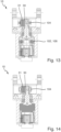
- the Fig. 1 shows a clamping and/or gripping device 10 for gripping an object (not shown) with two jaw elements 14 that are linearly movable between a closed position and an open position in a base housing 12.
- the clamping and/or gripping device 10 has a drive 16, wherein the drive 16 can be electrical, pneumatic, or manual, for example.
- the drive 16 can be electrical, pneumatic, or manual, for example.
- a gear unit 18 designed as a self-locking planetary gear 18A is arranged, which extends along a gear axis 20.
- the gear unit 18 is arranged in an extension housing 22, wherein the extension housing 22 is preferably flanged to the base housing 12. Alternatively, it is conceivable that the gear unit 18 is arranged in the base housing 12.
- the drive 16 is in Fig. 1 arranged on the extension housing 22. Alternatively, the drive 16 can also be arranged in the extension housing 22 or in the base housing 12.
- the gear unit 18 has according to Fig. 1 an input shaft 24 extending along the gear axis 20, rotatably mounted in the extension housing 22, and motion-coupled to a drive shaft 26 of the drive 16.
- the drive shaft 26 of the drive 16 forms the input shaft 24.
- the gear unit 18 further has an output shaft 28 extending along the gear axis 20, rotatably mounted in the base housing 12 and/or in the extension housing 22, and motion-coupled to the jaw elements 14 by means of a synchronization pinion 30.
- the synchronization pinion 30 interacts with rack profiles 31 provided on the jaw elements 14.
- the output shaft 28 rotates synchronously in the same direction of rotation.
- the output shaft 28 is coupled to the synchronization pinion 30 and thus sets the jaw elements 14 in motion.
- the input shaft 24 and the output shaft 28 rotate at different speeds. Depending on the number of teeth, the input shaft 24 and the output shaft 28 rotate in the same or opposite directions relative to the gear axis 20.
- the input torque DE is multiplied by the gear unit 18, so that the jaw elements 14 can be moved with increased force by an output torque DA that is higher than the input torque DE.
- the direction of rotation can be either clockwise or counterclockwise.
- the transmission unit 18 comprises a first ring gear H1, a sun gear S1, first planetary gears P1 arranged on a first planetary carrier T1, and a second ring gear H2.
- the first sun gear S1 is connected to the input shaft 24 and forms a first input member E1.
- three planetary gears P1 are provided; however, a different number is also conceivable.
- the planetary gears P1 each have a first planetary section 32 and a second planetary section 34, which are designed identically in this embodiment; However, different numbers of teeth and/or diameters are conceivable for the planetary sections 32, 34.
- the first planetary section 32 engages with the ring gear H1 and the second planetary section 34 engages with the second ring gear H2.
- the second ring gear H2 forms the first output member A1 and is coupled to the output shaft 28 via a bow spring clutch 102.
- the first ring gear H1 is coupled in a rotationally fixed manner to the base housing 12 and/or the extension housing 22. It is also conceivable for the base housing 12 and/or the extension housing 22 to form the first ring gear H1.
- the extension housing 22 is closed by a housing cover 36, which is screwed to the extension housing 22.
- the first planet carrier T1 is preferably rotatably arranged on the housing cover 36 and can rotate about the transmission axis 20 independently of the housing cover 36. For this purpose, a bearing can be provided between the housing cover 36 and the first planet carrier T1.
- At least one component of the transmission unit 18 is fixed, so that the input torque DE is converted into a higher output torque DA. Relative movements occur between the individual components of the transmission unit 18.
- the first ring gear H1 is fixed in a rotationally fixed manner relative to the extension housing 22.
- the components of the gear unit 18 move as follows:
- the first sun gear S1 is driven by the input shaft 24, thereby driving the planetary gears P1, which run on the fixed first ring gear H1 with the first planetary section 32.
- the planetary gears P1 rotate about their respective axes and perform a revolving movement about the transmission axis 20.
- This drives the second ring gear H2 with the second section 34.
- the second ring gear H2 thus rotates very slowly against the direction of rotation of the input shaft 24 with a high torque.
- the second ring gear H2 preferably drives the output shaft 28 or a subsequent drive element.
- FIG. 4 A gear shift diagram of a further embodiment of the planetary gear 18A is shown.
- the planetary gear 18A comprises a first ring gear H1, a first planet carrier T1 with one or more planetary gears P1 and a second ring gear H2.
- the planetary gears P1 are designed as stepped planets and have a first planetary section 32, which meshes with the first ring gear H1, and a second planetary section 34, which meshes with the second ring gear H2.
- the planet carrier T1 is coupled to the input shaft 24.
- the first ring gear 24 is torsionally rigidly connected to the base housing 12 and/or the extension housing 22.
- the second ring gear H2 represents the output of the planetary gear 18A and is coupled to the output shaft 28.
- Fig. 5 1 shows a gear shift diagram of a further embodiment of the planetary gear 18A.
- This is a single-stage planetary gear 18A with a positive stationary gear ratio and externally toothed spur gears as central gears.
- the planetary gear 18A comprises a first sun gear S1, a first planet carrier T1 with one or more planetary gears P1, and a second sun gear S2.
- the planetary gears P1 are designed as stepped planets and have a first planetary section 32 that meshes with the first sun gear S1 and a second planetary section 34 that meshes with the second sun gear S2.
- the sun gear is coupled to the input shaft 24.
- the second sun gear S2 represents the output of the planetary gear 18A and is coupled to the output shaft 28.
- Fig. 6 is a gear diagram of the embodiment of the planetary gear 18A according to Fig. 1 shown.
- This is a single-stage planetary gear 18A with a positive stationary ratio and two ring gears as central gears or a reduced planetary coupling gear (Wolfrom gear set).
- the planetary gear 18A comprises a sun gear S1, which is coupled to a planet carrier T1.
- One or more planetary gears P1 are provided on the planet carrier T1.
- a second ring gear H2 is provided.
- the planetary gears P1 have a first planetary section 32, which meshes with the first ring gear H1, and a second planetary section 34, which meshes with the second ring gear H2, wherein the planetary sections 32, 34 have the same toothing throughout.
- the same center distance between the ring gears H1, H2 and the planetary gears P1 can be achieved by profile shifting of the gears. It is also conceivable for the planetary gears P1 to have two different toothings, one of which meshes with the first ring gear H1 and the second with the second ring gear H2. Such an arrangement is also called a Wolfrom gear.
- the ring gears H1, H2 have a number of teeth in the range of 35 to 55 teeth, in particular in the range of 43 to 46 teeth and/or the planetary gears P1 have a number of teeth in the range of 10 to 20 teeth, in particular in the range of 12 to 15 teeth, and/or the sun gear S1 has a number of teeth in the range of 12 to 25 teeth, in particular in the range of 14 to 20 teeth.
- This preferred embodiment has the advantage of providing a higher overall gear ratio with fewer components and less installation space. This increases the power density, leading to a smaller end product. The requirements for self-locking are met, which is always a challenge, especially with compact gears.
- a further embodiment of a planetary gear 18A comprises a first ring gear H1, a planet carrier T1 with one or more planetary gears P1, and a second ring gear H2.
- the planetary gears P1 have a first planetary section 32 that meshes with the first ring gear H1 and a second planetary section 34 that meshes with the second ring gear H2, wherein the planetary sections 32, 34 have the same toothing. Since the first ring gear H1 and the second ring gear H2 have different numbers of teeth, the same center distance between the ring gears H1, H2 and the planetary gears P1 can be achieved by profile shifting of the gears. This embodiment enables more cost-effective production of the planetary gears P1.
- the ring gears H1, H2 have a number of teeth in the range of 35 to 55 teeth, in particular in the range of 43 to 46 teeth, and the planetary gears P1 have a number of teeth in the range of 10 to 20 teeth, in particular in the range of 12 to 15 teeth.
- Fig. 7 A further advantageous modification of the embodiment is shown, wherein preferably only one planetary gear P1 is used. With increasing size of the one planetary gear P1, this extends beyond the rotational axis 20 of the central gears. In this case, one speaks of an eccentric or an Akbar gear.
- the planetary gear P1 can be designed as a stepped planet or with continuous toothing. Thus, compared to the embodiment according to Fig. 6 a larger translation is achieved.
- a further advantageous embodiment of the transmission unit 18 with a first partial transmission G1 and a second partial transmission G2 is shown as a gear plan.
- the first partial transmission G1 comprises a first planetary carrier T1, at least one first planetary gear P1, a first ring gear H1 and a second ring gear H2.
- the first partial transmission G1 does not comprise a first sun gear.
- the second partial transmission G2 comprises a second planetary carrier T2, at least one second planetary gear P2, a second sun gear S2 and a third ring gear H3.
- the first planetary carrier T1 forms a first input element E1 and is coupled to the input shaft 24.
- the second ring gear H2 forms a first output element A1 and is coupled to the second sun gear S2.
- the sun gear S2 forms a second input element E2 of the second partial transmission G2.
- the third ring gear H3 forms the second output element A2 and can be coupled to the output shaft 28.
- the first planetary gear P1 has a first planetary section 32 and a second planetary section 34, wherein the first planetary section 32 interacts with the first ring gear H1 and the second planetary section 34 interacts with the second ring gear H2.
- the planetary sections 32, 34 are shown differently, but can be designed identically, which is made possible by a suitable selection of the number of teeth and profile shifts of the corresponding components H1, H2 and P1.
- the first ring gear H1 and the second planetary carrier T2 are preferably arranged relative to the base housing 12 and/or the Attachment housing 22. This is compared to the embodiment according to Fig. 6 a larger translation is achieved.
- All embodiments of the transmission unit 18 have in common that the input shaft 24 and the output shaft 28 run along the transmission axis 20; these can be hollow in order to guide sensor cables or other supply lines through.
- the gripping or clamping device 10 has according to Fig. 1 further comprises a gripping force maintaining means 100.
- the gripping force maintaining means 100 is designed as a bow spring coupling 102 according to the Fig. 9 to 12 formed.
- a gripping force maintenance can be achieved on the jaw elements 14.
- the combination of the self-locking planetary gear 18A in conjunction with the arc spring clutch 102 is accompanied by the advantages that, due to the flexibility introduced into the drive train by the arc spring clutch 102 and the non-reversibility of the self-locking planetary gear 18A, a gripping force maintenance with as little loss as possible can be achieved, and that the clamping or gripping device 10 can be reduced by means of the arc spring clutch 102 by means of the arc spring clutch.
- the arc spring clutch 102 is preferably arranged between the second output member A2 and the output shaft 24, wherein the second output member A2 is rotationally coupled to the arc spring clutch 102.
- the arc spring coupling 102 has according to Fig. 9 to 12 a lower shell 138 and an upper shell 140, wherein the lower shell 138 and the upper shell 140 are coupled to each other by means of two arc springs 142.
- the lower shell 138 is rotationally coupled to the second output member A2.
- the upper shell 140 is rotationally coupled to the output shaft 28.
- the second ring gear H2 When the second ring gear H2 forms the second output element, the second ring gear H2 is rotationally coupled to the arc spring clutch 102.
- the lower shell 138 has two drivers 139 facing the planetary gear 18, which, when assembled, engage in two recesses 37 of the second ring gear H2 facing the arc spring clutch 30.
- the recesses are arranged on the sun gear, on the planetary gears, or on the planet carrier.
- the lower shell 138 has according to Figs. 11 and 12 a shell base 144, a circular bearing inner ring 146 and a circular bearing outer ring 148, which together define a partially circular spring receptacle 150 for receiving the arc springs 142.
- Fig. 12 at an angle of 180° to each other, an inner drive web 152A on the bearing inner ring 146 and an outer drive web 152B on the bearing outer ring 148.
- the bearing inner ring 146, the bearing outer ring 148 and the drive webs 152A, 152B protrude parallel to the gear axis 20 relative to the shell bottom 144.
- the bow springs 142 extend according to Fig. 12 each along a spring axis 154, which runs along a circular circumference or a partial circular circumference around the gear axis 20.
- the arc springs 142 are arranged in the spring holder 150, slightly preloaded, and are supported on the inner drive webs 152A and the outer drive webs 152B.
- the arc springs 142 reduce the force pulses or force peaks and, due to their flexibility, also ensure almost loss-free force maintenance on the jaw elements 14.
- the upper shell 140 has according to Figs. 11 and 12 a shell cover 156 and two coupling webs 158, wherein the coupling webs 158 are spaced at an angle of 180°.
- the shell cover 156 closes the spring receptacle 150.
- the coupling webs 158 are each arranged radially between the inner drive web 152A and the outer drive web 152B with respect to the gear axis 20. In the assembled and spring-unloaded state, the coupling webs 158 are arranged in a space 153 between the inner drive web 152A and the outer drive web 152B.
- the coupling webs 158 are designed such that they intersect the spring axis 154.
- the drive webs 152A, 152B interact with the arc springs 142 such that the arc spring 142 can be driven in rotation by means of the lower shell 138.
- the coupling webs 158 interact with the arc springs 142 such that the upper shell 140 can be driven in rotation by means of the arc springs 142.
- the arc spring clutch 102 is designed such that, when no load torque acts on the output shaft 28 or the upper shell 140, no or only an insignificant relative rotational movement takes place between the lower shell 138 and the arc springs 142 and/or between the lower shell 138 and the upper shell 140 when the lower shell 138 rotates about the transmission axis 20.
- the arc spring clutch 102 is further configured such that, when a load torque acts on the output shaft 28 or the upper shell 140, a relative rotational movement occurs between the lower shell 138 and the arc springs 142 and/or between the lower shell 138 and the upper shell 140 upon rotation of the lower shell 138 about the transmission axis 20.
- the clutch webs 158 move out of the space between the drive webs 152A, 152B along the spring axis 154. In the process, the arc springs 142 are compressed.
- a jaw toothing 160 is provided, which is connected to the Synchronization pinion 30 cooperates.
- the output shaft 28 and the synchronization pinion 30 can be formed as a single piece or as a multi-piece, rotating piece.
- the output shaft 28 is preferably arranged perpendicular to the transmission axis 20 between the two jaw elements 14.
- the lower shell 138 is sleeve-shaped and has a central opening 164, which, in the assembled state, accommodates a pin 166 arranged on the upper shell 140 and extending along the transmission axis 20.
- the pin 166 is preferably hollow so that a transmission element of the transmission unit 18, e.g., the input shaft 22 or the output member A2, can project into the pin 166.
- the pin 166 preferably extends along 360° around the transmission axis 20.
- the pin 166 extends according to Fig. 12 by less than 320°, in particular less than 280°, preferably less than 240°, and preferably less than 220°.
- the pin 166 forms a gap 168 into which a rotation stop 170 arranged on the lower shell 138 extends.
- the rotation stop 170 is preferably formed integrally with the lower shell 138. It is advantageous if the rotation stop 170, in conjunction with the pin 166, also provides a sleeve-shaped recess.
- Such interaction between a partially circular pin 166 and a rotation stop 170 prevents the permissible spring travel of the arc spring 142 from being exceeded or the arc spring 142 from blocking.
- the distance in the unloaded state between the rotation stop 170 and the end of the pin 166 is preferably in a range between 30° and 70°, more preferably between 40° and 60°, preferably 50°.
- a particularly preferred embodiment of the invention provides that the pin 166 extends through an angle in the range between 150° and 110°, in particular in the range between 140° and 120°, preferably 130°.
- the rotation stop 170 extends through an angle in the range between 150° and 110°, in particular in the range between 140° and 120°, preferably 130°.
- the rotation stop 170 extends through the same angle as the pin 166. Accordingly, the masses of the pin 166 and the rotation stop 170 balance each other out, so that there is no imbalance.
- the pin 166 and the rotation stop 170 each extend through an angle of 130° around the gear axis 20, the lower shell 138 and the upper shell 140 can each be rotated by 50° in both directions of rotation.
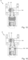
- the gripping device 10 is shown with different embodiments of the gripping force maintenance means 100.
- the gripping force maintenance means 100 can preferably have a translatory elasticity means 104 and/or a separately designed rotary elasticity means 106.
- the elasticity means 104, 106 can be designed as spring means and/or elastomer means.
- a spring in particular a bow spring 102, and/or an elastomer can be provided as the rotational elasticity means 106.
- a spring and/or an elastomer can be provided as the translational elasticity means 104.
- the translational elasticity means 104 and the rotational elasticity means 106 are preferably arranged at a distance from one another.
- the translational elasticity means 104 is arranged in a guide assembly of the synchronization pinion 30 and/or the rack profile 31 of the jaw elements 14.
- the properties and/or targeted design of the elastic/spring elements allow for greater dissipation of kinetic energy in the output train. This allows the gripping impulse generated during operation, which can be higher than the original gripping force, to be limited to a predetermined range.
- kinetic energy is converted into spring energy. If a workpiece is lost, the elasticity (the mechanical spring) relaxes, causing the jaw elements 14 to move in the axial direction. This movement is preferably detected by a position measuring system and can be used for workpiece loss detection in the gripper control system.
- the rotary elasticity means 106 is designed as a bow spring 102, and the translatory elasticity means 104 is designed as a mechanical spring, particularly made of plastic or metal. Due to the combination of two adjustable, additive elasticities, the force curve can be influenced by two different options for maintaining the gripping force over a wide range. Accordingly, the adaptability and behavior of the mechatronic gripper are significantly improved. In addition, larger spring travels can be realized, which enables gripping impulse reduction and workpiece loss detection. Furthermore, the force curve (operating point) can be changed over a wider range by specifically adjusting the properties of the spring elements.
- a rotational elasticity means rather than a rotational elasticity means.
- a translational elasticity means 104 in the form of a mechanical spring, in particular made of plastic or metal, and no rotational elasticity means is provided.
- a smaller possibility of adjustability is The elasticity is preserved, as only a gripping force-maintaining elasticity element is used. This has the advantage of allowing for larger spring travel, which enables gripping impulse reduction and workpiece loss detection.
- a translatory elasticity means 104 in the form of an elastomer element, in particular made of plastic or metal, and a rotational elasticity means 106 in the form of a bow spring 102 are provided.
- kinetic energy is converted into spring energy. If a workpiece is lost, the elasticity (the mechanical spring) relaxes, causing the base jaw to move in the axial direction. This movement is preferably detected by a position measuring system and can be used to detect workpiece loss in the gripper control system.
- the gripping force maintenance means 100 can be provided in a simpler and more cost-effective manner compared to the first embodiment.
Landscapes
- Engineering & Computer Science (AREA)
- Mechanical Engineering (AREA)
- General Engineering & Computer Science (AREA)
- Robotics (AREA)
- Retarders (AREA)
Applications Claiming Priority (1)
| Application Number | Priority Date | Filing Date | Title |
|---|---|---|---|
| DE102023132197.8A DE102023132197A1 (de) | 2023-11-20 | 2023-11-20 | Greif- und/oder Spannvorrichtung mit einem hemmenden Getriebe |
Publications (1)
| Publication Number | Publication Date |
|---|---|
| EP4556176A1 true EP4556176A1 (fr) | 2025-05-21 |
Family
ID=93376234
Family Applications (1)
| Application Number | Title | Priority Date | Filing Date |
|---|---|---|---|
| EP24210282.0A Pending EP4556176A1 (fr) | 2023-11-20 | 2024-10-31 | Dispositif de préhension et/ou de serrage doté d'une transmission à effet inhibiteur |
Country Status (4)
| Country | Link |
|---|---|
| US (1) | US20250162135A1 (fr) |
| EP (1) | EP4556176A1 (fr) |
| CN (1) | CN120020411A (fr) |
| DE (1) | DE102023132197A1 (fr) |
Citations (6)
| Publication number | Priority date | Publication date | Assignee | Title |
|---|---|---|---|---|
| EP1905549A1 (fr) | 2006-09-26 | 2008-04-02 | Zimmer, Gunther | Dispositif de prise doté d'un engrenage hélicoïdal spacial |
| EP1485636B1 (fr) * | 2002-03-13 | 2009-04-22 | Robert Bosch Gmbh | Mecanisme de commande |
| EP3079862B1 (fr) * | 2013-12-11 | 2018-02-14 | Günther Zimmer | Dispositif d'entraînement pour un dispositif de préhension |
| KR20180018123A (ko) * | 2016-08-12 | 2018-02-21 | 주식회사 만도 | 유성기어장치 |
| DE102019125415B4 (de) * | 2019-09-20 | 2021-08-12 | Schunk Gmbh & Co. Kg Spann- Und Greiftechnik | Getriebeeinheit für eine Greif- oder Spannvorrichtung und Greif- oder Spannvorrichtung mit automatischem Umschalten zwischen Eilgang und Kraftgang |
| DE102023108107A1 (de) * | 2022-03-30 | 2023-10-05 | Illinois Tool Works Inc. | Planetengetriebe |
Family Cites Families (12)
| Publication number | Priority date | Publication date | Assignee | Title |
|---|---|---|---|---|
| US1522774A (en) * | 1921-06-04 | 1925-01-13 | John T Kerwin | Shaft coupling |
| US4590820A (en) * | 1983-03-31 | 1986-05-27 | Dresser Industries, Inc. | Rotational power transmission apparatus |
| DE29706616U1 (de) * | 1997-04-12 | 1997-07-24 | Schwarzwälder Uhrwerke-Fabrik Burger GmbH & Co KG, 78136 Schonach | Planetengetriebe |
| DE202008017689U1 (de) * | 2008-02-26 | 2010-03-25 | Metabowerke Gmbh | Planetengetriebe für ein Elektrohandwerkzeuggerät sowie Elektrohandwerkzeuggerät |
| EP2146112A1 (fr) * | 2008-07-14 | 2010-01-20 | Tribecraft AG | Train épicycloïdal de wolfram |
| JP3156145U (ja) * | 2009-10-05 | 2009-12-17 | シュンク・ジャパン株式会社 | 平行開閉型ロボットハンド機構 |
| DE102010056068A1 (de) * | 2010-12-23 | 2012-06-28 | Ps Automation Gmbh | Planetengetriebe, Planet und Planetenrad für ein Planetengetriebe, Handantriebseinrichtung und Antrieb mit einem Planetengetriebe |
| DE102013207179B4 (de) * | 2013-04-19 | 2018-01-11 | Schunk Gmbh & Co. Kg Spann- Und Greiftechnik | Greif-Schwenk-Einheit |
| DE102014220110A1 (de) * | 2014-10-02 | 2016-04-07 | Schunk Gmbh & Co. Kg Spann- Und Greiftechnik | Greif- oder Schwenkeinheit |
| AT516751B1 (de) * | 2015-02-03 | 2016-08-15 | Tectos Gmbh | Drehelastische wellenkupplung |
| WO2019144355A1 (fr) * | 2018-01-25 | 2019-08-01 | 深圳市固胜智能科技有限公司 | Mâchoire de serrage électrique |
| EP3670115B1 (fr) * | 2018-12-20 | 2021-10-20 | Tecan Trading Ag | Module de transmission, module de préhension pourvu de module de transmission et dispositif préhension pourvu de module de préhension |
-
2023
- 2023-11-20 DE DE102023132197.8A patent/DE102023132197A1/de active Pending
-
2024
- 2024-10-31 EP EP24210282.0A patent/EP4556176A1/fr active Pending
- 2024-11-15 US US18/949,049 patent/US20250162135A1/en active Pending
- 2024-11-19 CN CN202411650388.XA patent/CN120020411A/zh active Pending
Patent Citations (6)
| Publication number | Priority date | Publication date | Assignee | Title |
|---|---|---|---|---|
| EP1485636B1 (fr) * | 2002-03-13 | 2009-04-22 | Robert Bosch Gmbh | Mecanisme de commande |
| EP1905549A1 (fr) | 2006-09-26 | 2008-04-02 | Zimmer, Gunther | Dispositif de prise doté d'un engrenage hélicoïdal spacial |
| EP3079862B1 (fr) * | 2013-12-11 | 2018-02-14 | Günther Zimmer | Dispositif d'entraînement pour un dispositif de préhension |
| KR20180018123A (ko) * | 2016-08-12 | 2018-02-21 | 주식회사 만도 | 유성기어장치 |
| DE102019125415B4 (de) * | 2019-09-20 | 2021-08-12 | Schunk Gmbh & Co. Kg Spann- Und Greiftechnik | Getriebeeinheit für eine Greif- oder Spannvorrichtung und Greif- oder Spannvorrichtung mit automatischem Umschalten zwischen Eilgang und Kraftgang |
| DE102023108107A1 (de) * | 2022-03-30 | 2023-10-05 | Illinois Tool Works Inc. | Planetengetriebe |
Also Published As
| Publication number | Publication date |
|---|---|
| CN120020411A (zh) | 2025-05-20 |
| DE102023132197A1 (de) | 2025-05-22 |
| US20250162135A1 (en) | 2025-05-22 |
Similar Documents
| Publication | Publication Date | Title |
|---|---|---|
| AT409030B (de) | Vorrichtung zur verstellung einer nockenwelle | |
| WO2021078892A1 (fr) | Transmission, train d'entraînement et véhicule comprenant une transmission | |
| WO2016000897A1 (fr) | Transmission multi-vitesse pour véhicules ferroviaires | |
| EP2513510A1 (fr) | Transmission | |
| DE102009027468A1 (de) | Kraftübertragungsanordnung | |
| EP2736150A2 (fr) | Entraînement linéaire | |
| EP1836083B1 (fr) | Dispositif de superposition de tours-minute comprenant un entrainement d'assistance | |
| WO2008052865A1 (fr) | Liaison de transmission entre un arbre de changement de vitesse et une masse supplémentaire | |
| DE102011108473A1 (de) | Planetengetriebe | |
| EP4071007B1 (fr) | Actuateur de blocage, organe de frein doté d'un tel actuateur de blocage et frein de service et/ou de stationnement | |
| DE102021113744A1 (de) | Gurtaufroller mit einem Elektromotor | |
| EP0617680A1 (fr) | Engrenage a chaine a rapport de transmission variable et a chaine dentee | |
| DE102012206434A1 (de) | Antriebsanordnung für ein Fahrzeug | |
| DE102008039009A1 (de) | Nockenwellenversteller | |
| DE102012212140B4 (de) | Bremsvorrichtung für eine direkt elektromechanisch aktuierte Planetengetriebeanordnung eines Sitzverstellmechanismus und Verfahren zum Betrieb einer Bremsvorrichtung | |
| DE19519310A1 (de) | Differentialgetriebe für einen elektromotorisch betriebenen Bremsaktor | |
| EP3059402A1 (fr) | Dispositif de decalage de phase de l'angle de rotation d'une partie d'entrainement vers une partie actionnee | |
| EP2359029A1 (fr) | Transmission | |
| DE102008036743A1 (de) | Getriebe mit Slots | |
| EP4556176A1 (fr) | Dispositif de préhension et/ou de serrage doté d'une transmission à effet inhibiteur | |
| EP3892889A1 (fr) | Transmission à démultiplication harmonique | |
| EP2128490A2 (fr) | Excentrique train épicyloidal | |
| EP1827938A1 (fr) | Actionneur destine a actionner deux organes mecaniques | |
| DE4238788A1 (de) | Umlaufrollengetriebe | |
| EP1910707A1 (fr) | Mecanisme de commande pour des instruments, pourvu d'un engrenage planetaire |
Legal Events
| Date | Code | Title | Description |
|---|---|---|---|
| PUAI | Public reference made under article 153(3) epc to a published international application that has entered the european phase |
Free format text: ORIGINAL CODE: 0009012 |
|
| STAA | Information on the status of an ep patent application or granted ep patent |
Free format text: STATUS: THE APPLICATION HAS BEEN PUBLISHED |
|
| AK | Designated contracting states |
Kind code of ref document: A1 Designated state(s): AL AT BE BG CH CY CZ DE DK EE ES FI FR GB GR HR HU IE IS IT LI LT LU LV MC ME MK MT NL NO PL PT RO RS SE SI SK SM TR |
|
| STAA | Information on the status of an ep patent application or granted ep patent |
Free format text: STATUS: REQUEST FOR EXAMINATION WAS MADE |
|
| 17P | Request for examination filed |
Effective date: 20251110 |