EP4556184A2 - Brosse à poils et bande transporteuse formée d'une pluralité desdites brosses à poils - Google Patents
Brosse à poils et bande transporteuse formée d'une pluralité desdites brosses à poils Download PDFInfo
- Publication number
- EP4556184A2 EP4556184A2 EP25169292.7A EP25169292A EP4556184A2 EP 4556184 A2 EP4556184 A2 EP 4556184A2 EP 25169292 A EP25169292 A EP 25169292A EP 4556184 A2 EP4556184 A2 EP 4556184A2
- Authority
- EP
- European Patent Office
- Prior art keywords
- support plate
- bristle brush
- brush according
- bristle
- brushes
- Prior art date
- Legal status (The legal status is an assumption and is not a legal conclusion. Google has not performed a legal analysis and makes no representation as to the accuracy of the status listed.)
- Pending
Links
Images


Classifications
-
- B—PERFORMING OPERATIONS; TRANSPORTING
- B65—CONVEYING; PACKING; STORING; HANDLING THIN OR FILAMENTARY MATERIAL
- B65G—TRANSPORT OR STORAGE DEVICES, e.g. CONVEYORS FOR LOADING OR TIPPING, SHOP CONVEYOR SYSTEMS OR PNEUMATIC TUBE CONVEYORS
- B65G15/00—Conveyors having endless load-conveying surfaces, i.e. belts and like continuous members, to which tractive effort is transmitted by means other than endless driving elements of similar configuration
- B65G15/30—Belts or like endless load-carriers
- B65G15/32—Belts or like endless load-carriers made of rubber or plastics
- B65G15/42—Belts or like endless load-carriers made of rubber or plastics having ribs, ridges, or other surface projections
-
- B—PERFORMING OPERATIONS; TRANSPORTING
- B65—CONVEYING; PACKING; STORING; HANDLING THIN OR FILAMENTARY MATERIAL
- B65G—TRANSPORT OR STORAGE DEVICES, e.g. CONVEYORS FOR LOADING OR TIPPING, SHOP CONVEYOR SYSTEMS OR PNEUMATIC TUBE CONVEYORS
- B65G15/00—Conveyors having endless load-conveying surfaces, i.e. belts and like continuous members, to which tractive effort is transmitted by means other than endless driving elements of similar configuration
- B65G15/30—Belts or like endless load-carriers
- B65G15/58—Belts or like endless load-carriers with means for holding or retaining the loads in fixed position, e.g. magnetic
-
- B—PERFORMING OPERATIONS; TRANSPORTING
- B26—HAND CUTTING TOOLS; CUTTING; SEVERING
- B26D—CUTTING; DETAILS COMMON TO MACHINES FOR PERFORATING, PUNCHING, CUTTING-OUT, STAMPING-OUT OR SEVERING
- B26D7/00—Details of apparatus for cutting, cutting-out, stamping-out, punching, perforating, or severing by means other than cutting
- B26D7/20—Cutting beds
-
- B—PERFORMING OPERATIONS; TRANSPORTING
- B26—HAND CUTTING TOOLS; CUTTING; SEVERING
- B26D—CUTTING; DETAILS COMMON TO MACHINES FOR PERFORATING, PUNCHING, CUTTING-OUT, STAMPING-OUT OR SEVERING
- B26D7/00—Details of apparatus for cutting, cutting-out, stamping-out, punching, perforating, or severing by means other than cutting
- B26D7/27—Means for performing other operations combined with cutting
- B26D7/32—Means for performing other operations combined with cutting for conveying or stacking cut product
Definitions
- the present invention relates to a bristle brush, which is modular and enables forming, by joining a plurality of said brushes, a homogeneous base, such as an endless conveyor belt.
- Brushes are currently known which, when duly fixed to a set of mechanical elements, form a movable surface by way of an endless conveyor belt.
- Said conveyor belts are used in different industrial areas to transport and/or handle elements which must be elevated, or which cannot be in contact with a rigid or continuous surface.
- brushes comprising a plurality of bristles mechanically fixed to a support plate and multiple brushes are linked to form a larger surface or conveyor belt.
- This system has several drawbacks, such as the manufacturing cost (fixing the bristles to a support plate), the weight (said support plate must be thick in order to properly fix the bristles), the power required to move the conveyor belt (the greater the weight, the higher the power required), etc.
- EP 2 656 987 A1 describes a plastic, modular and self-engaging bristle brush, comprising a set of runners including a pair of opposite guiding and self-centring ends which project from the perimeter of the brush, said runners being distributed so that the ends of contiguous brush runners are able to fit together by overlapping each other.
- said runners include at their guiding and self-centring ends articulated joining means between contiguous brushes for the self-engaging thereof, converting the set of multiple brushes into a cutting base, leaving the material above it, enabling its handling, cutting, die-cutting, etc., which in turn forms an endless conveyor belt.
- the bristle modules preferably injected, moulded or printed in 3D, are manufactured in different materials with different hardnesses for different applications, either cutting, handling or transport on an endless belt.
- the materials of the bristle brushes were relatively rigid plastics, and a specific turning radius was necessary to rotate the conveyor belt, generally greater than 150 mm.
- highly flexible materials were chosen, the handling being easier and more pleasant, and at the same time allowing very low turning radii, from 30 mm, due to the bending of the base.
- an object of the present invention is to provide a bristle brush that is very flexible, allowing a conveyor belt to achieve very small turning radii.
- the bristle brush according to the present invention comprises a support plate, a plurality of flexible bristles emerging from one of the surfaces thereof, and said support plate comprising coupling elements, the ends of the bristles furthest from the support plate defining a support surface intended to receive a part to be transported and/or cut or handled, wherein said support plate comprises a leading edge and a trailing edge, said leading and trailing edges comprising complementary shapes, for example, complementary recesses and projections, or a polygonal shape, for example, hexagonal, which enables a plurality of brushes to be assembled in a staggered or interspersed manner.
- the geometry of the bristle brush as described above, enables a homogeneous transition to be obtained when passing over a gear or roller during its movement forming a conveyor belt, especially in the change of direction at the end of said conveyor belt, since the flexible materials tend to yield slightly in the shaft area, creating micro-separations between the brushes.
- said support plate also comprises coupling elements.
- said coupling elements are anchors provided with a longitudinal hole. This longitudinal hole is for placing a tie and traction rod.
- said anchors are associated in pairs, the longitudinal holes of the anchors defining two longitudinal axes on the leading edge and two longitudinal axes on the trailing edge, each for corresponding traction rods.
- the brush can have a polygonal shape with any number of faces, not necessarily quadrangular.
- the brush has an equidistant regular distribution of the traction shafts.
- said coupling elements are flanges that fit in complementary housings.
- said flanges are preferably placed in the projections of the support plate and said housings are placed in the recesses of the support plate.
- said support plate is smooth on its surface opposite the flexible bristles, said opposite surface comprising an adhesive substrate.
- This smooth support plate can be used, in particular, when the end of the conveyor belt is a cylinder without steps or pull notches, generally used in belts that do not need precise positioning and that move at a higher speed.
- said adhesive substrate is coated with a protective sheet before its first use, which is removed to fix the support plate.
- each projection of the leading and trailing edge of the support plate is formed by a straight central portion and two straight side portions, arranged perpendicularly or at any other oblique angle.
- the present invention also relates to a conveyor belt formed by a plurality of bristle brushes as described above, the brushes being joined in a staggered manner thanks to the complementary shapes of the leading and trailing edges.
- the lower surface of the support plate of the bristle brushes seeks to adapt the conventional belts made of laminar material so that they have a surface of bristles that enables robotic systems to be used and also be incorporated in static work and handling surfaces to enable productivity to be increased in activities that require the lower handling of the elements or materials (cutting, die-cutting, linear objects, organic materials, compact and low-rise flat elements, etc.), and also in activities in which the collection must be fast and preferably lower, since it avoids the physical contact of the hand with the rigid or robotised surface of the support.
- This functionality significantly simplifies the design of the robot clamps, enabling "gravital picking", without the need for a vacuum or sophisticated actions. It also enables multiple collection (“multipicking"), reducing the movements of the robot by being able to transport in one same movement different objects or different amounts.
- this design is very useful for collaborative works, combined work carried out by robots and cobots (collaborative robots) and people.
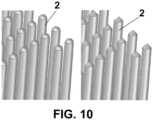
- the design of the bristle has been perfected, ending with a hemispherical or conical surface, offering a more comfortable interaction with the hand of the operator or of the robot, and enabling a more secure entry of the tools that can be used, such as blades, drills or dies.
- the modules can be injected into one or more materials to combine their properties.
- a bristle brush can be injected combining a harder and more resistant polymer for the area of the anchors, to improve its mechanical performance, with a softer and smoother polymer in the rest of the base and the bristles, to offer better bending of the base in the turn and a more pleasant touch on the bristles.
- These injected modules are very useful given their simplicity, versatility and their economic cost compared to alternative solutions.
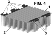
- FIGS 1 to 4 an example of a bristle brush not forming part of the present invention is shown, comprising a support plate 1 from which a plurality of flexible bristles 2 extends, in particular, extending from an upper surface of said support plate 1.
- Said support plate 1 defines four edges, a leading edge 11, a trailing edge 12 and two side edges 13.
- Said leading 11 and trailing 12 edges comprise complementary recesses and projections, said projections having, for example, a trapezoidal shape, defining a straight central portion and two side portions also straight, at an oblique angle.
- Said support plate 1 further comprises coupling elements, which in this embodiment are anchors 3, each of which comprises a longitudinal hole for placing a traction rod.
- Said anchors 3 are associated in pairs, so that they define two longitudinal shafts for corresponding traction rods. Two of these traction rods, which are not shown in the figures, are placed on the leading edge 11 and two traction rods are placed on the trailing edge 12.
- Said supporting plate 1 comprises a plurality of notches 14 on the lower surface thereof to enable traction thereof by means of gears (not shown), when a plurality of brushes according to the present invention is used as a conveyor belt.
- Figure 3 shows how several brushes are assembled by means of the complementary recesses and projections, the brushes being assembled in an interspersed or staggered manner.
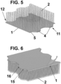
- This embodiment differs from the example in that the support plate is smooth on the lower surface thereof and comprises an adhesive substrate 15, which before being fixed to a surface is coated by a protective sheet 16.
- the coupling elements are flanges 4 which are housed in complementary housings 5.
- said flanges 4 are preferably placed in the projections, while the housings 5 are preferably placed in the recesses.
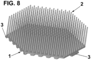
- Figure 7 shows a part of a conveyor belt according to a present invention formed by a plurality of bristle brushes, where it is shown that small turning radii can be achieved thanks to the flexibility of the brush material, in particular, of the support plate 1.
- said support plate 1 has a hexagonal shape, a plurality of staggered brushes being mounted ( Figure 9 ), for example, by an anchor 3 on the leading edge 11 thereof and two anchors 3 on the trailing edge 12 thereof.
Landscapes
- Engineering & Computer Science (AREA)
- Mechanical Engineering (AREA)
- Life Sciences & Earth Sciences (AREA)
- Forests & Forestry (AREA)
- Brushes (AREA)
- Belt Conveyors (AREA)
- Structure Of Belt Conveyors (AREA)
- Details Of Cutting Devices (AREA)
- Chain Conveyers (AREA)
Priority Applications (2)
| Application Number | Priority Date | Filing Date | Title |
|---|---|---|---|
| EP25169292.7A EP4556184A3 (fr) | 2019-05-13 | 2019-05-13 | Brosse à poils et bande transporteuse formée d'une pluralité desdites brosses à poils |
| MA71478A MA71478A (fr) | 2019-05-13 | 2019-05-13 | Brosse à poils et bande transporteuse formée d'une pluralité desdites brosses à poils |
Applications Claiming Priority (2)
| Application Number | Priority Date | Filing Date | Title |
|---|---|---|---|
| EP25169292.7A EP4556184A3 (fr) | 2019-05-13 | 2019-05-13 | Brosse à poils et bande transporteuse formée d'une pluralité desdites brosses à poils |
| EP19382370.5A EP3738733A1 (fr) | 2019-05-13 | 2019-05-13 | Brosse à poils et courroie de convoyeur formées par une pluralité desdites brosses à poils |
Related Parent Applications (1)
| Application Number | Title | Priority Date | Filing Date |
|---|---|---|---|
| EP19382370.5A Division EP3738733A1 (fr) | 2019-05-13 | 2019-05-13 | Brosse à poils et courroie de convoyeur formées par une pluralité desdites brosses à poils |
Publications (2)
| Publication Number | Publication Date |
|---|---|
| EP4556184A2 true EP4556184A2 (fr) | 2025-05-21 |
| EP4556184A3 EP4556184A3 (fr) | 2025-07-02 |
Family
ID=66677087
Family Applications (2)
| Application Number | Title | Priority Date | Filing Date |
|---|---|---|---|
| EP19382370.5A Pending EP3738733A1 (fr) | 2019-05-13 | 2019-05-13 | Brosse à poils et courroie de convoyeur formées par une pluralité desdites brosses à poils |
| EP25169292.7A Pending EP4556184A3 (fr) | 2019-05-13 | 2019-05-13 | Brosse à poils et bande transporteuse formée d'une pluralité desdites brosses à poils |
Family Applications Before (1)
| Application Number | Title | Priority Date | Filing Date |
|---|---|---|---|
| EP19382370.5A Pending EP3738733A1 (fr) | 2019-05-13 | 2019-05-13 | Brosse à poils et courroie de convoyeur formées par une pluralité desdites brosses à poils |
Country Status (7)
| Country | Link |
|---|---|
| US (1) | US11845611B2 (fr) |
| EP (2) | EP3738733A1 (fr) |
| JP (2) | JP7695206B2 (fr) |
| CN (2) | CN114174026A (fr) |
| MA (1) | MA71478A (fr) |
| MX (2) | MX2021013926A (fr) |
| WO (1) | WO2020229454A1 (fr) |
Families Citing this family (3)
| Publication number | Priority date | Publication date | Assignee | Title |
|---|---|---|---|---|
| FR3108547B1 (fr) * | 2020-03-27 | 2022-04-01 | Lectra | Elément modulaire de support de coupe à aspiration d’une machine de coupe automatique de matériaux en feuilles |
| FR3111836B1 (fr) * | 2020-06-24 | 2022-07-08 | Lectra | Convoyeur de coupe à aspiration d’une machine de coupe automatique par lame de matériaux en feuilles |
| EP4071090A1 (fr) | 2021-04-08 | 2022-10-12 | Open Mind Ventures, S.L.U. | Module de brosse pour courroies de convoyeur |
Citations (1)
| Publication number | Priority date | Publication date | Assignee | Title |
|---|---|---|---|---|
| EP2656987A1 (fr) | 2012-04-16 | 2013-10-30 | Manufacturas y Transformados AB, S.L. | Brosse en soie, matière plastique, modulaire et à auto-prise |
Family Cites Families (27)
| Publication number | Priority date | Publication date | Assignee | Title |
|---|---|---|---|---|
| ES8101972A1 (es) * | 1979-01-31 | 1980-12-16 | Gerber Garment Technology Inc | Perfeccionamientos en un aparato para trabajar sobre mate- rial laminar |
| DE2908701A1 (de) * | 1979-03-06 | 1980-09-11 | Guenter O Stumpf | Vorrichtung zum aufnehmen und festhalten von bahnfoermigem material, insbesondere von mehreren uebereinanderliegenden stoffbahnen, fuer eine zuschneidemaschine |
| JPS58144514U (ja) * | 1982-03-23 | 1983-09-29 | 株式会社マキ製作所 | 仕分け用スラットコンベアの搬送体 |
| US4476756A (en) * | 1982-04-12 | 1984-10-16 | Gerber Garment Technology, Inc. | Apparatus for working limp sheet material on a conveyor |
| US4572357A (en) * | 1984-01-26 | 1986-02-25 | Gerber Garment Technology, Inc. | Sheet material conveyor with unloading apparatus |
| US4685363A (en) * | 1985-05-22 | 1987-08-11 | Gerber Scientific, Inc. | Apparatus and method for supporting and working on sheet material |
| US4925016A (en) * | 1987-10-06 | 1990-05-15 | The Laitram Corporation | Heavy duty modular conveyor belt and sprocket with unique tracking |
| US5125504A (en) * | 1991-03-08 | 1992-06-30 | Rexnord Corporation | Modular conveyor chain having open hinge pin construction |
| US5189936A (en) * | 1991-04-05 | 1993-03-02 | Gerber Garment Technology, Inc. | Conveyor for supporting and advancing sheet material and cutting machine including such conveyor |
| US5228554A (en) * | 1991-09-20 | 1993-07-20 | Gerber Garment Technology, Inc. | Material take-off ramp and system for a conveyor cutter bed and method of use |
| JP2507821Y2 (ja) * | 1992-12-02 | 1996-08-21 | グンゼ株式会社 | 自動裁断機のバキュ―ム吸引力増強用フィルム |
| US5596917A (en) * | 1994-02-18 | 1997-01-28 | Gerber Garment Technology, Inc. | Apparatus for conveying and cutting sheet material on a vacuum bed with system for sealing end portions of the bed |
| EP1063448A3 (fr) * | 1999-06-22 | 2003-11-12 | NORDDEUTSCHE SEEKABELWERKE GMBH & CO. KG | Courroie, en particulier courroie transporteuse et procédé pour sa fabrication |
| US7284657B2 (en) * | 2002-10-21 | 2007-10-23 | Keystone Manufacturing, Inc. | Modular conveyor belt with unique link capture means |
| AU2003902499A0 (en) * | 2003-05-22 | 2003-06-05 | Scott Messenger | A conveyor belt |
| US7097030B2 (en) | 2004-10-19 | 2006-08-29 | Laitram, L.L.C. | Long, flexible conveyor belt modules in modular plastic conveyor belts |
| CA2585685C (fr) * | 2004-11-03 | 2013-07-23 | Thermodrive Llc. | Raccord de courroie thermoplastique |
| US7344020B2 (en) * | 2005-06-10 | 2008-03-18 | Deere & Company | Belt connection for agriculture conveyor |
| JP4979129B2 (ja) * | 2007-09-21 | 2012-07-18 | 株式会社島精機製作所 | 裁断機 |
| DE102009020304A1 (de) | 2009-05-07 | 2010-11-25 | Hastem-Müller, Stefan | Glied für ein Gliederband |
| JP5779966B2 (ja) * | 2011-05-09 | 2015-09-16 | 横浜ゴム株式会社 | コンベヤベルト |
| CN104229390A (zh) * | 2014-09-26 | 2014-12-24 | 无锡优萌模塑制造有限公司 | 一种塑料链板 |
| ES2594480B1 (es) * | 2015-06-19 | 2017-09-27 | Manufacturas Y Transformados Ab, S.L. | Estructura reticular flexible |
| CN107487585A (zh) * | 2017-08-15 | 2017-12-19 | 合肥横冲机械科技有限公司 | 一种可拼接式物料输送带 |
| CN208023956U (zh) * | 2018-02-14 | 2018-10-30 | 中阳德欣科技有限公司 | 一种可调节的建筑模板 |
| CN208470744U (zh) * | 2018-07-23 | 2019-02-05 | 新绛县大唐云雕漆艺厂 | 一种云雕漆器生产用的上料机构 |
| CN108974942A (zh) * | 2018-08-03 | 2018-12-11 | 江苏光天耐材科技有限公司 | 一种用于陶瓷过滤片的传送装置 |
-
2019
- 2019-05-13 EP EP19382370.5A patent/EP3738733A1/fr active Pending
- 2019-05-13 EP EP25169292.7A patent/EP4556184A3/fr active Pending
- 2019-05-13 MA MA71478A patent/MA71478A/fr unknown
-
2020
- 2020-05-12 CN CN202080043007.5A patent/CN114174026A/zh active Pending
- 2020-05-12 JP JP2021568172A patent/JP7695206B2/ja active Active
- 2020-05-12 CN CN202511641698.XA patent/CN121247308A/zh active Pending
- 2020-05-12 WO PCT/EP2020/063158 patent/WO2020229454A1/fr not_active Ceased
- 2020-05-12 MX MX2021013926A patent/MX2021013926A/es unknown
- 2020-05-12 US US17/610,781 patent/US11845611B2/en active Active
-
2025
- 2025-05-09 MX MX2025005450A patent/MX2025005450A/es unknown
- 2025-06-06 JP JP2025095110A patent/JP2025122250A/ja active Pending
Patent Citations (1)
| Publication number | Priority date | Publication date | Assignee | Title |
|---|---|---|---|---|
| EP2656987A1 (fr) | 2012-04-16 | 2013-10-30 | Manufacturas y Transformados AB, S.L. | Brosse en soie, matière plastique, modulaire et à auto-prise |
Also Published As
| Publication number | Publication date |
|---|---|
| MX2025005450A (es) | 2025-06-02 |
| MA71478A (fr) | 2025-04-30 |
| CN114174026A (zh) | 2022-03-11 |
| JP2025122250A (ja) | 2025-08-20 |
| WO2020229454A1 (fr) | 2020-11-19 |
| JP2022533115A (ja) | 2022-07-21 |
| MX2021013926A (es) | 2022-01-07 |
| CN121247308A (zh) | 2026-01-02 |
| US20220306391A1 (en) | 2022-09-29 |
| US11845611B2 (en) | 2023-12-19 |
| JP7695206B2 (ja) | 2025-06-18 |
| EP3738733A1 (fr) | 2020-11-18 |
| EP4556184A3 (fr) | 2025-07-02 |
Similar Documents
| Publication | Publication Date | Title |
|---|---|---|
| US11845611B2 (en) | Bristle brush and conveyor belt formed by a plurality of said bristle brushes | |
| EP2656987B1 (fr) | Brosse en soie, matière plastique, modulaire et à auto-prise | |
| JP4749494B1 (ja) | ケーブル類保護案内用多関節支持部材 | |
| EP3106411B1 (fr) | Structure réticulaire flexible | |
| US5630500A (en) | Positive geared tracking pulley and belt for a reversible conveyor belt system | |
| EP3822049B1 (fr) | Systeme de prehension pour elements | |
| CA2104472A1 (fr) | Outil de coupe ameliore | |
| EP3530594B1 (fr) | Structure réticulaire flexible | |
| US12486113B2 (en) | Conveyor belt formed by a plurality of bristle brushes | |
| EP3738720A1 (fr) | Système de manipulation d'éléments | |
| EP4071090A1 (fr) | Module de brosse pour courroies de convoyeur | |
| HK40128171A (en) | Bristle brush and conveyor belt formed by a plurality of said bristle brushes | |
| EP1982946B1 (fr) | Chaîne de transport pour voie de transport | |
| EP2138429B1 (fr) | Transporteur à bande | |
| DE102017115854B4 (de) | Manipulationsgreifer, Manipulationsgreifersystemmodul und modulares Manipulationsgreifersystem aus demselben | |
| US20220203570A1 (en) | Bristle brush | |
| JP2011112224A (ja) | 多関節型ケーブル類保護案内装置 | |
| EP3135612A1 (fr) | Système de convoyage de pot | |
| JP6822885B2 (ja) | コンベアベルト | |
| WO2026061896A1 (fr) | Préhenseur pour saisir un produit, en particulier un produit alimentaire | |
| JPS6120740B2 (fr) |
Legal Events
| Date | Code | Title | Description |
|---|---|---|---|
| PUAI | Public reference made under article 153(3) epc to a published international application that has entered the european phase |
Free format text: ORIGINAL CODE: 0009012 |
|
| STAA | Information on the status of an ep patent application or granted ep patent |
Free format text: STATUS: THE APPLICATION HAS BEEN PUBLISHED |
|
| AC | Divisional application: reference to earlier application |
Ref document number: 3738733 Country of ref document: EP Kind code of ref document: P |
|
| AK | Designated contracting states |
Kind code of ref document: A2 Designated state(s): AL AT BE BG CH CY CZ DE DK EE ES FI FR GB GR HR HU IE IS IT LI LT LU LV MC MK MT NL NO PL PT RO RS SE SI SK SM TR |
|
| PUAL | Search report despatched |
Free format text: ORIGINAL CODE: 0009013 |
|
| AK | Designated contracting states |
Kind code of ref document: A3 Designated state(s): AL AT BE BG CH CY CZ DE DK EE ES FI FR GB GR HR HU IE IS IT LI LT LU LV MC MK MT NL NO PL PT RO RS SE SI SK SM TR |
|
| RIC1 | Information provided on ipc code assigned before grant |
Ipc: B26D 7/20 20060101AFI20250526BHEP |
|
| STAA | Information on the status of an ep patent application or granted ep patent |
Free format text: STATUS: REQUEST FOR EXAMINATION WAS MADE |
|
| 17P | Request for examination filed |
Effective date: 20251219 |
|
| DAX | Request for extension of the european patent (deleted) | ||
| REG | Reference to a national code |
Ref country code: HK Ref legal event code: DE Ref document number: 40128171 Country of ref document: HK |