EP4556341A2 - Dispositif d'affichage pour un véhicule, procédé d'affichage et support d'informations - Google Patents
Dispositif d'affichage pour un véhicule, procédé d'affichage et support d'informations Download PDFInfo
- Publication number
- EP4556341A2 EP4556341A2 EP25168062.5A EP25168062A EP4556341A2 EP 4556341 A2 EP4556341 A2 EP 4556341A2 EP 25168062 A EP25168062 A EP 25168062A EP 4556341 A2 EP4556341 A2 EP 4556341A2
- Authority
- EP
- European Patent Office
- Prior art keywords
- display
- lane
- vehicle
- confirmation
- lane change
- Prior art date
- Legal status (The legal status is an assumption and is not a legal conclusion. Google has not performed a legal analysis and makes no representation as to the accuracy of the status listed.)
- Pending
Links
Images




Classifications
-
- B—PERFORMING OPERATIONS; TRANSPORTING
- B60—VEHICLES IN GENERAL
- B60W—CONJOINT CONTROL OF VEHICLE SUB-UNITS OF DIFFERENT TYPE OR DIFFERENT FUNCTION; CONTROL SYSTEMS SPECIALLY ADAPTED FOR HYBRID VEHICLES; ROAD VEHICLE DRIVE CONTROL SYSTEMS FOR PURPOSES NOT RELATED TO THE CONTROL OF A PARTICULAR SUB-UNIT
- B60W30/00—Purposes of road vehicle drive control systems not related to the control of a particular sub-unit, e.g. of systems using conjoint control of vehicle sub-units
- B60W30/10—Path keeping
- B60W30/12—Lane keeping
-
- B—PERFORMING OPERATIONS; TRANSPORTING
- B60—VEHICLES IN GENERAL
- B60K—ARRANGEMENT OR MOUNTING OF PROPULSION UNITS OR OF TRANSMISSIONS IN VEHICLES; ARRANGEMENT OR MOUNTING OF PLURAL DIVERSE PRIME-MOVERS IN VEHICLES; AUXILIARY DRIVES FOR VEHICLES; INSTRUMENTATION OR DASHBOARDS FOR VEHICLES; ARRANGEMENTS IN CONNECTION WITH COOLING, AIR INTAKE, GAS EXHAUST OR FUEL SUPPLY OF PROPULSION UNITS IN VEHICLES
- B60K35/00—Instruments specially adapted for vehicles; Arrangement of instruments in or on vehicles
- B60K35/20—Output arrangements, i.e. from vehicle to user, associated with vehicle functions or specially adapted therefor
- B60K35/21—Output arrangements, i.e. from vehicle to user, associated with vehicle functions or specially adapted therefor using visual output, e.g. blinking lights or matrix displays
- B60K35/22—Display screens
-
- B—PERFORMING OPERATIONS; TRANSPORTING
- B60—VEHICLES IN GENERAL
- B60K—ARRANGEMENT OR MOUNTING OF PROPULSION UNITS OR OF TRANSMISSIONS IN VEHICLES; ARRANGEMENT OR MOUNTING OF PLURAL DIVERSE PRIME-MOVERS IN VEHICLES; AUXILIARY DRIVES FOR VEHICLES; INSTRUMENTATION OR DASHBOARDS FOR VEHICLES; ARRANGEMENTS IN CONNECTION WITH COOLING, AIR INTAKE, GAS EXHAUST OR FUEL SUPPLY OF PROPULSION UNITS IN VEHICLES
- B60K35/00—Instruments specially adapted for vehicles; Arrangement of instruments in or on vehicles
- B60K35/80—Arrangements for controlling instruments
- B60K35/81—Arrangements for controlling instruments for controlling displays
-
- B—PERFORMING OPERATIONS; TRANSPORTING
- B60—VEHICLES IN GENERAL
- B60W—CONJOINT CONTROL OF VEHICLE SUB-UNITS OF DIFFERENT TYPE OR DIFFERENT FUNCTION; CONTROL SYSTEMS SPECIALLY ADAPTED FOR HYBRID VEHICLES; ROAD VEHICLE DRIVE CONTROL SYSTEMS FOR PURPOSES NOT RELATED TO THE CONTROL OF A PARTICULAR SUB-UNIT
- B60W30/00—Purposes of road vehicle drive control systems not related to the control of a particular sub-unit, e.g. of systems using conjoint control of vehicle sub-units
- B60W30/18—Propelling the vehicle
- B60W30/18009—Propelling the vehicle related to particular drive situations
- B60W30/18163—Lane change; Overtaking manoeuvres
-
- B—PERFORMING OPERATIONS; TRANSPORTING
- B60—VEHICLES IN GENERAL
- B60W—CONJOINT CONTROL OF VEHICLE SUB-UNITS OF DIFFERENT TYPE OR DIFFERENT FUNCTION; CONTROL SYSTEMS SPECIALLY ADAPTED FOR HYBRID VEHICLES; ROAD VEHICLE DRIVE CONTROL SYSTEMS FOR PURPOSES NOT RELATED TO THE CONTROL OF A PARTICULAR SUB-UNIT
- B60W50/00—Details of control systems for road vehicle drive control not related to the control of a particular sub-unit, e.g. process diagnostic or vehicle driver interfaces
- B60W50/08—Interaction between the driver and the control system
- B60W50/14—Means for informing the driver, warning the driver or prompting a driver intervention
-
- B—PERFORMING OPERATIONS; TRANSPORTING
- B60—VEHICLES IN GENERAL
- B60W—CONJOINT CONTROL OF VEHICLE SUB-UNITS OF DIFFERENT TYPE OR DIFFERENT FUNCTION; CONTROL SYSTEMS SPECIALLY ADAPTED FOR HYBRID VEHICLES; ROAD VEHICLE DRIVE CONTROL SYSTEMS FOR PURPOSES NOT RELATED TO THE CONTROL OF A PARTICULAR SUB-UNIT
- B60W60/00—Drive control systems specially adapted for autonomous road vehicles
- B60W60/001—Planning or execution of driving tasks
-
- B—PERFORMING OPERATIONS; TRANSPORTING
- B60—VEHICLES IN GENERAL
- B60K—ARRANGEMENT OR MOUNTING OF PROPULSION UNITS OR OF TRANSMISSIONS IN VEHICLES; ARRANGEMENT OR MOUNTING OF PLURAL DIVERSE PRIME-MOVERS IN VEHICLES; AUXILIARY DRIVES FOR VEHICLES; INSTRUMENTATION OR DASHBOARDS FOR VEHICLES; ARRANGEMENTS IN CONNECTION WITH COOLING, AIR INTAKE, GAS EXHAUST OR FUEL SUPPLY OF PROPULSION UNITS IN VEHICLES
- B60K2360/00—Indexing scheme associated with groups B60K35/00 or B60K37/00 relating to details of instruments or dashboards
- B60K2360/16—Type of output information
- B60K2360/175—Autonomous driving
-
- B—PERFORMING OPERATIONS; TRANSPORTING
- B60—VEHICLES IN GENERAL
- B60K—ARRANGEMENT OR MOUNTING OF PROPULSION UNITS OR OF TRANSMISSIONS IN VEHICLES; ARRANGEMENT OR MOUNTING OF PLURAL DIVERSE PRIME-MOVERS IN VEHICLES; AUXILIARY DRIVES FOR VEHICLES; INSTRUMENTATION OR DASHBOARDS FOR VEHICLES; ARRANGEMENTS IN CONNECTION WITH COOLING, AIR INTAKE, GAS EXHAUST OR FUEL SUPPLY OF PROPULSION UNITS IN VEHICLES
- B60K2360/00—Indexing scheme associated with groups B60K35/00 or B60K37/00 relating to details of instruments or dashboards
- B60K2360/16—Type of output information
- B60K2360/178—Warnings
-
- B—PERFORMING OPERATIONS; TRANSPORTING
- B60—VEHICLES IN GENERAL
- B60K—ARRANGEMENT OR MOUNTING OF PROPULSION UNITS OR OF TRANSMISSIONS IN VEHICLES; ARRANGEMENT OR MOUNTING OF PLURAL DIVERSE PRIME-MOVERS IN VEHICLES; AUXILIARY DRIVES FOR VEHICLES; INSTRUMENTATION OR DASHBOARDS FOR VEHICLES; ARRANGEMENTS IN CONNECTION WITH COOLING, AIR INTAKE, GAS EXHAUST OR FUEL SUPPLY OF PROPULSION UNITS IN VEHICLES
- B60K2360/00—Indexing scheme associated with groups B60K35/00 or B60K37/00 relating to details of instruments or dashboards
- B60K2360/16—Type of output information
- B60K2360/179—Distances to obstacles or vehicles
-
- B—PERFORMING OPERATIONS; TRANSPORTING
- B60—VEHICLES IN GENERAL
- B60K—ARRANGEMENT OR MOUNTING OF PROPULSION UNITS OR OF TRANSMISSIONS IN VEHICLES; ARRANGEMENT OR MOUNTING OF PLURAL DIVERSE PRIME-MOVERS IN VEHICLES; AUXILIARY DRIVES FOR VEHICLES; INSTRUMENTATION OR DASHBOARDS FOR VEHICLES; ARRANGEMENTS IN CONNECTION WITH COOLING, AIR INTAKE, GAS EXHAUST OR FUEL SUPPLY OF PROPULSION UNITS IN VEHICLES
- B60K35/00—Instruments specially adapted for vehicles; Arrangement of instruments in or on vehicles
- B60K35/10—Input arrangements, i.e. from user to vehicle, associated with vehicle functions or specially adapted therefor
-
- B—PERFORMING OPERATIONS; TRANSPORTING
- B60—VEHICLES IN GENERAL
- B60K—ARRANGEMENT OR MOUNTING OF PROPULSION UNITS OR OF TRANSMISSIONS IN VEHICLES; ARRANGEMENT OR MOUNTING OF PLURAL DIVERSE PRIME-MOVERS IN VEHICLES; AUXILIARY DRIVES FOR VEHICLES; INSTRUMENTATION OR DASHBOARDS FOR VEHICLES; ARRANGEMENTS IN CONNECTION WITH COOLING, AIR INTAKE, GAS EXHAUST OR FUEL SUPPLY OF PROPULSION UNITS IN VEHICLES
- B60K35/00—Instruments specially adapted for vehicles; Arrangement of instruments in or on vehicles
- B60K35/20—Output arrangements, i.e. from vehicle to user, associated with vehicle functions or specially adapted therefor
- B60K35/21—Output arrangements, i.e. from vehicle to user, associated with vehicle functions or specially adapted therefor using visual output, e.g. blinking lights or matrix displays
- B60K35/23—Head-up displays [HUD]
-
- B—PERFORMING OPERATIONS; TRANSPORTING
- B60—VEHICLES IN GENERAL
- B60K—ARRANGEMENT OR MOUNTING OF PROPULSION UNITS OR OF TRANSMISSIONS IN VEHICLES; ARRANGEMENT OR MOUNTING OF PLURAL DIVERSE PRIME-MOVERS IN VEHICLES; AUXILIARY DRIVES FOR VEHICLES; INSTRUMENTATION OR DASHBOARDS FOR VEHICLES; ARRANGEMENTS IN CONNECTION WITH COOLING, AIR INTAKE, GAS EXHAUST OR FUEL SUPPLY OF PROPULSION UNITS IN VEHICLES
- B60K35/00—Instruments specially adapted for vehicles; Arrangement of instruments in or on vehicles
- B60K35/20—Output arrangements, i.e. from vehicle to user, associated with vehicle functions or specially adapted therefor
- B60K35/28—Output arrangements, i.e. from vehicle to user, associated with vehicle functions or specially adapted therefor characterised by the type of the output information, e.g. video entertainment or vehicle dynamics information; characterised by the purpose of the output information, e.g. for attracting the attention of the driver
-
- B—PERFORMING OPERATIONS; TRANSPORTING
- B60—VEHICLES IN GENERAL
- B60K—ARRANGEMENT OR MOUNTING OF PROPULSION UNITS OR OF TRANSMISSIONS IN VEHICLES; ARRANGEMENT OR MOUNTING OF PLURAL DIVERSE PRIME-MOVERS IN VEHICLES; AUXILIARY DRIVES FOR VEHICLES; INSTRUMENTATION OR DASHBOARDS FOR VEHICLES; ARRANGEMENTS IN CONNECTION WITH COOLING, AIR INTAKE, GAS EXHAUST OR FUEL SUPPLY OF PROPULSION UNITS IN VEHICLES
- B60K35/00—Instruments specially adapted for vehicles; Arrangement of instruments in or on vehicles
- B60K35/60—Instruments characterised by their location or relative disposition in or on vehicles
-
- B—PERFORMING OPERATIONS; TRANSPORTING
- B60—VEHICLES IN GENERAL
- B60K—ARRANGEMENT OR MOUNTING OF PROPULSION UNITS OR OF TRANSMISSIONS IN VEHICLES; ARRANGEMENT OR MOUNTING OF PLURAL DIVERSE PRIME-MOVERS IN VEHICLES; AUXILIARY DRIVES FOR VEHICLES; INSTRUMENTATION OR DASHBOARDS FOR VEHICLES; ARRANGEMENTS IN CONNECTION WITH COOLING, AIR INTAKE, GAS EXHAUST OR FUEL SUPPLY OF PROPULSION UNITS IN VEHICLES
- B60K35/00—Instruments specially adapted for vehicles; Arrangement of instruments in or on vehicles
- B60K35/65—Instruments specially adapted for specific vehicle types or users, e.g. for left- or right-hand drive
- B60K35/652—Instruments specially adapted for specific vehicle types or users, e.g. for left- or right-hand drive for left- or right-hand drive
-
- B—PERFORMING OPERATIONS; TRANSPORTING
- B60—VEHICLES IN GENERAL
- B60W—CONJOINT CONTROL OF VEHICLE SUB-UNITS OF DIFFERENT TYPE OR DIFFERENT FUNCTION; CONTROL SYSTEMS SPECIALLY ADAPTED FOR HYBRID VEHICLES; ROAD VEHICLE DRIVE CONTROL SYSTEMS FOR PURPOSES NOT RELATED TO THE CONTROL OF A PARTICULAR SUB-UNIT
- B60W50/00—Details of control systems for road vehicle drive control not related to the control of a particular sub-unit, e.g. process diagnostic or vehicle driver interfaces
- B60W50/08—Interaction between the driver and the control system
- B60W50/14—Means for informing the driver, warning the driver or prompting a driver intervention
- B60W2050/146—Display means
Definitions
- the present disclosure relates to a display device for a vehicle, a display method and a program.
- Patent Application Laid-Open ( JP-A) No. 2020-044988 recites a display device for a vehicle that, when a lane change is conducted by autonomous driving (driving control) of the vehicle, displays information relating to the lane change.
- This display device for a vehicle displays an image of an arrow or the like showing a direction from a lane in which the vehicle is running to a lane of the intended change.
- the display device for a vehicle displays the image of the arrow in different forms in states before and after the lane change is started.
- a vehicle occupant may be aware of the lane change destination lane, the state before the lane change starts and the state after the lane change starts.
- JP-A No. 2020-044988 a vehicle occupant may not be aware of whether or not the vehicle can perceive conditions of the lane change destination lane. As a result, the vehicle occupant may feel unsafe during the lane change.
- the present disclosure is to provide a display device for a vehicle, a display method and a program that may provide a sense of safety to a vehicle occupant when a lane change is conducted by autonomous driving of the vehicle.
- a display device for a vehicle includes: a display section provided in a cabin of a vehicle that is capable of autonomous driving; and a control section that, before conducting a lane change by autonomous driving from a first lane in which the vehicle is running to a second lane that is distinct from the first lane, causes the display section to display a lane display corresponding to the first lane and the second lane and a confirmation display relating to confirmation of a condition of the second lane.
- the display section is provided in the vehicle cabin.
- the display device for a vehicle also includes the control section.
- the control section causes the display unit to display the lane display corresponding to the first lane and the second lane. Therefore, by looking at the display section, a vehicle occupant may identify the second lane that is the lane change destination.
- the control section causes the display section to display the confirmation display relating to confirmation of the condition of the second lane. Therefore, by seeing the display unit, the vehicle occupant may understand that the condition of the second lane has been confirmed by the vehicle before the lane change. Thus, the vehicle occupant may be provided with a sense of safety.
- autonomous driving is intended to include a running mode of the vehicle in which some or all of operations of acceleration, braking, direction indication, steering and the like are conducted autonomously.
- control section causes the display section to display the confirmation display regardless of whether or not another vehicle that is distinct from the vehicle is present in the second lane.
- the confirmation display is displayed at the display unit regardless of whether or not there is another vehicle in the second lane. Therefore, by seeing the display unit, the vehicle occupant may understand that the condition of the second lane has been confirmed, regardless of a state of congestion of the road. Thus, the vehicle occupant may be provided with an even greater sense of safety.
- the control section causes the display section to display a first confirmation display as the confirmation display, the first confirmation display depicting a start of acquisition of vicinity information including the condition of the second lane.
- the vehicle occupant may understand that the vehicle is acquiring vicinity information before the lane change.
- the vehicle occupant may be provided with a sense of safety.
- control section causes the display section to display a second confirmation display as the confirmation display, the second confirmation display depicting a goal position of the vehicle after the lane change.
- the vehicle occupant may understand that the vehicle has confirmed the goal position after the lane change.
- the vehicle occupant may be provided with a sense of safety.
- the control section causes the display section to display a second confirmation display depicting a goal position of the vehicle after the lane change.
- the second confirmation display is displayed after the first confirmation display. Therefore, by looking at the display section, the vehicle occupant may understand the progress of the vehicle in deciding the goal position while checking the condition of the lane change destination lane.
- the control section acquires a determination result from an autonomous driving control section that determines whether or not a goal position is available based on the vicinity information, and when a determination result that a goal position is available is acquired, causes the display section to display the second confirmation display based on the determination result.
- the second confirmation display is displayed when the goal position has been decided on the basis of the vicinity information. Therefore, in this display device for a vehicle, the display of the first confirmation display followed by the display of the second confirmation display at the display section may reliably reflect control steps relating to autonomous driving.
- the control section causes the display section to display an other vehicle display superposed with the lane display, the other vehicle display corresponding to another vehicle that is distinct from the vehicle in the second lane, and the second confirmation display being displayed at a position that does not overlap with a front side or a rear side of the other vehicle display.
- the other vehicle display corresponding to another vehicle in the second lane is displayed at the display unit, superposed on the lane display.
- the second confirmation display is displayed at a position that does not overlap with the front side or rear side of the other vehicle display. Therefore, by looking at the display section, the vehicle occupant may understand that the goal position after the lane change has been confirmed by the vehicle with consideration for the presence of other vehicles. Thus, the vehicle occupant may be provided with a sense of safety.
- control section causes the display section to display a third confirmation display as the confirmation display, the third confirmation display depicting that the lane change to the goal position is possible.
- the vehicle occupant may understand that preparation for the lane change is ready at the vehicle side. Therefore, the vehicle occupant may be prepared for the lane change. Thus, the vehicle occupant may be provided with an even greater sense of safety before the lane change.
- the second confirmation display displayed at the display section is a line-shaped graphic extending in a road width direction on the lane display corresponding to the second lane
- the third confirmation display displayed at the display section is an area-shaped graphic with a predetermined size on the lane display corresponding to the second lane.
- the line-shaped graphic indicates the goal position after the lane change
- the area-shaped graphic indicates that the lane change is possible.
- a sense of presence of the confirmation display may be progressively strengthened by the change of display from the line-shaped graphic to the area-shaped graphic. Therefore, the vehicle occupant may intuitively understand the phased confirmation operations associated with the lane change. That is, when other vehicles are running in the lane change destination lane and distances between vehicles must be thoroughly assured before the lane change, the vehicle occupant may be advised, by the display of the third confirmation display as an area-shaped graphic, that a space into which the vehicle can conduct the lane change is available in the lane being changed to. Therefore, the vehicle occupant may intuitively understand the phased confirmation operations associated with the lane change.
- the control section causes the display section to display the third confirmation display depicting that the lane change to the goal position is possible.
- the third confirmation display is displayed after the second confirmation display. Therefore, by looking at the display section, the vehicle occupant may understand the progress of the vehicle in confirming the possibility of the lane change to the goal position while checking the condition of the lane change destination lane.
- the control section acquires a determination result from an autonomous driving control section that determines whether or not the lane change to the goal position is possible, and when a determination result that the lane change to the goal position is possible is acquired, causes the display section to display the third confirmation display based on the determination result.
- the third confirmation display is displayed when the determination result indicating that the lane change to the destination location is possible is acquired by the autonomous driving control section. Therefore, in this display device for a vehicle, the display of the second confirmation display followed by the display of the third confirmation display at the display section may reliably reflect control steps relating to autonomous driving.
- control section causes the display section to delete the confirmation display and display an execution display when the vehicle is conducting the lane change to the second lane, the execution display depicting the vehicle conducting the lane change to the second lane.
- the vehicle occupant may understand that the lane change is being conducted.
- the vehicle occupant may understand the phases of confirmation of vicinity conditions by the vehicle and execution of the lane change that are associated with the lane change of the vehicle, and the vehicle occupant may understand control of the vehicle associated with the lane change in more detail.
- the vehicle occupant may be provided with a sense of safety.
- the display section is at least one of an instrument display of an instrument display apparatus provided at an instrument panel to the vehicle front of a driver seat or a projection screen at the vehicle upper side of the instrument display, which projection screen is projected onto by a head-up display device.
- the display section is the instrument display provided to the vehicle front of the driver seat, the projection screen at the vehicle upper side of the instrument cluster, or the like, an occupant of the driver seat may check the display unit without greatly moving their eyeline. Therefore, because both a vista to the vehicle front side and control of the vehicle associated with the lane change may be checked easily, the vehicle occupant may be provided with an even greater sense of safety.
- a display method includes: displaying a lane display and a confirmation display at a display section provided in a cabin of a vehicle that is capable of autonomous driving, the lane display corresponding to a first lane in which the vehicle is running and a second lane that is distinct from the first lane, and the confirmation display relating to confirmation of a condition of the second lane; and conducting a lane change by autonomous driving from the first lane to the second lane, the lane display and the confirmation display being displayed before the lane change is conducted.
- a vehicle occupant may be provided with a sense of safety when a lane change is conducted by autonomous driving of the vehicle.
- a program causes a computer to execute processing including: displaying a lane display and a confirmation display at a display section provided in a cabin of a vehicle that is capable of autonomous driving, the lane display corresponding to a first lane in which the vehicle is running and a second lane that is distinct from the first lane, and the confirmation display relating to confirmation of a condition of the second lane; and conducting a lane change by autonomous driving from the first lane to the second lane, the lane display and the confirmation display being displayed before the lane change is conducted.
- a vehicle occupant may be provided with a sense of safety when a lane change is conducted by autonomous driving of the vehicle.
- a vehicle occupant may be provided with a sense of safety when a lane change is conducted by autonomous driving of a vehicle.
- a display device for a vehicle 10 according to an exemplary embodiment is employed in a vehicle 12, which is described with reference to the drawings.
- the vehicle 12 according to the present exemplary embodiment is configured to be switchable between autonomous driving and manual driving.
- autonomous driving as used herein is intended to include a running mode of the vehicle in which some or all of operations of acceleration, braking, direction indication, steering and the like are conducted autonomously.
- manual driving is intended to include a running mode of the vehicle in which a driver executes all driving operations (operations of acceleration, braking, direction indication, steering and the like).
- an instrument panel 14 is provided at a front portion of a cabin interior of the vehicle 12.
- the instrument panel 14 extends in the vehicle width direction, and a steering wheel 16 is provided at the vehicle right side of the instrument panel 14. That is, the present exemplary embodiment is an example of a right-hand drive car in which the steering wheel 16 is provided at the right side and a driver seat is set at the vehicle right side.
- a windshield glass 18 is provided at a front end portion of the instrument panel 14.
- the windshield glass 18 extends in the vehicle vertical direction and the vehicle width direction, dividing the cabin interior from the cabin exterior.
- a vehicle right side end portion of the windshield glass 18 is fixed to a vehicle right side front pillar 20.
- the front pillar 20 extends in the vehicle vertical direction, and the windshield glass 18 is fixed to a vehicle width direction inner side end portion of the front pillar 20.
- a front end portion of a front side glass 22 is fixed to a vehicle width direction outer side end portion of the front pillar 20.
- a vehicle left side end portion of the windshield glass 18 is fixed to a vehicle left side front pillar, which is not shown in the drawings.
- a first display unit 24 that serves as a display section is provided at the instrument panel 14.
- the first display unit 24 is constituted by an instrument display provided at the instrument panel 14 to the vehicle front of the driver seat.
- the instrument display structures a portion of an instrument display apparatus, which is not shown in the drawings, connected to various instruments installed in the vehicle 12.
- the first display unit 24 is provided at a location within a field of view of the driver in the state in which the eyeline of the driver is oriented to the vehicle front.
- a second display unit 26 is provided at the windshield glass 18.
- the second display unit 26 is provided at the vehicle upper side relative to the first display unit 24.
- the second display unit 26 is constituted by a projection screen that is projected onto by a head-up display (HUD) device 44 (see Fig. 2 ).
- HUD head-up display
- the head-up display device 44 is provided at the vehicle front side relative to the instrument panel 14, and the head-up display device 44 is structured to project images onto the second display unit 26 of the windshield glass 18.
- FIG. 2 is a block diagram showing hardware structures of the display device for a vehicle 10.
- the ECU 28 of the display device for a vehicle 10 includes a central processing unit (CPU) 30, read-only memory (ROM) 32, random access memory (RAM) 34, storage 36, a communications interface 38 and an input/output interface 40. These structures are connected to be capable of communicating with one another via a bus 42.
- the CPU 30 is an example of a processor
- the RAM 34 is an example of memory.
- the CPU 30 is a central arithmetic processing unit that executes various programs and controls respective parts. That is, the CPU 30 reads a program from the ROM 32 or the storage 36, and executes the program using the RAM 34 as a workspace. The CPU 30 performs control of the structures described above and various kinds of computational processing in accordance with programs recorded in the ROM 32 or the storage 36.
- the ROM 32 stores various programs and various kinds of data.
- the RAM 34 serves as a workspace, temporarily memorizing programs and data.
- the storage 36 includes a hard disk drive (HDD) or solid state drive (SSD).
- the storage 36 stores various programs, including an operating system, and various kinds of data.
- the ROM 32 or the storage 36 stores a program for implementing display processing, and various kinds of data and the like.
- the communications interface 38 is an interface for the display device for a vehicle 10 to communicate with a server and other equipment, which are not shown in the drawings.
- the communications interface 38 employs a standard such as, for example, Ethernet (registered trademark), LTE, FDDI, Wi-Fi (registered trademark) or the like.
- the input/output interface 40 is connected with the first display unit 24, the head-up display device 44 that projects images onto the second display unit 26, and actuators 46.
- the actuators 46 include a steering actuator, an accelerator actuator and a brake actuator.
- the steering actuator conducts steering of the vehicle 12.
- the accelerator actuator conducts acceleration of the vehicle 12.
- the brake actuator conducts deceleration of the vehicle 12 by controlling a brake.
- Sensors, a GPS device and the like for allowing autonomous driving of the vehicle 12, which are not shown in the drawings, are connected to the input/output interface 40.
- the display device for a vehicle 10 uses the hardware resources described above to realize various functions.
- the functional structures realized by the display device for a vehicle 10 are described with reference to Fig. 3 .
- the display device for a vehicle 10 includes, as functional structures, a communication section 50, an acquisition section 51, a driving plan specification section 52, an autonomous driving control section 54, an image generation section 56, a display command section 58 and a display emphasis section 60.
- These functional structures are realized by the CPU 30 reading and executing a program memorized in the ROM 32 or the storage 36.
- the communication section 50 sends and receives data to and from the external server and other equipment via the communications interface 38.
- the communication section 50 sends and receives data such as map data, traffic data and the like stored in a server.
- the communication section 50 is also configured to conduct vehicle-to-vehicle communications with vehicles in the vicinity.
- the acquisition section 51 acquires a running environment of the vehicle 12 that serves as vicinity information from external sensors, which are not shown in the drawings.
- the external sensors include cameras that image predetermined ranges, millimeter-wave radar that transmits probing waves in a predetermined range, and lidar (light detection and ranging/laser imaging detection and ranging) that scans a predetermined range.
- the vicinity information includes, for example, a width of a road on which the vehicle 12 is running, other vehicles running near the vehicle 12, obstacles and so forth.
- the driving plan specification section 52 specifies a driving plan of the vehicle 12. More specifically, a destination location is entered by a vehicle occupant and the driving plan specification section 52 specifies a driving plan from a current location to the destination location.
- the autonomous driving control section 54 causes autonomous driving of the vehicle 12 in accordance with the specified driving plan, taking account of position information and environment information of the vicinity of the vehicle 12. More specifically, the vehicle 12 is autonomously driven by control of the actuators 46.
- the image generation section 56 generates images for display at the first display unit 24.
- the image generation section 56 displays confirmation displays at the first display unit 24 when a lane change of the vehicle 12 is to be conducted by autonomous driving in accordance with the driving plan specified by the driving plan specification section 52.
- the confirmation displays are displays relating to confirmation of conditions in a lane change destination lane.
- the confirmation displays include a first confirmation display P1, a second confirmation display P2 and a third confirmation display P3, which are described below.
- the display command section 58 includes a function for displaying images generated by the image generation section 56 at the first display unit 24, and a function for deleting images displayed at the first display unit 24. Below, functions of the image generation section 56 and display command section 58 are described with reference to Fig. 4 to Fig. 9 .
- lane displays L relating to the shape of a road and lane information
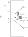
- a present vehicle display V1 and other vehicle displays V2 and V3 are displayed at a central portion of a display region of the first display unit 24.
- the lane displays L are images representing a lane in which the present vehicle is running and lanes to which the present vehicle may change from the lane in which the present vehicle is running.
- the present vehicle display V1 is an image representing the present vehicle.
- the other vehicle displays V2 and V3 are images representing vehicles running in the vicinity of the present vehicle, which are other vehicles distinct from the present vehicle. Looking at the display example in Fig.
- the lane displays L, the present vehicle display V1 and the other vehicle displays V2 and V3 are respectively displayed on the basis of information detected from any or a combination of the GPS device, map data, and the various sensors installed in the vehicle 12.
- the position of the present vehicle may be detected by the GPS device installed in the vehicle 12.
- sensors such as stereo cameras, an ultrasonic sensor, the millimeter-wave radar, laser radar and the like may be used in combination.
- the position of the present vehicle and the positions of vehicles in the vicinity may be identified by vehicle-to-vehicle communications with the vehicles in the vicinity.
- An intended running route R of the present vehicle is displayed superposed with the lane displays L at the central portion of the display region of the first display unit 24.
- the intended running route R is an image schematically showing a route of the vehicle 12 that is predicted on the basis of the driving plan specified by the driving plan specification section 52.
- the intended running route R is shown as, for example, a belt-shaped graphic extending along the lane displays L. Plural dots are displayed in perspective, disposed at equally spaced positions on the route.
- confirmation displays that are displayed before a lane change of the vehicle 12 is conducted by autonomous driving are described in specific terms with reference to Fig. 5 to Fig. 8 .
- these drawings illustrate a situation in which the present vehicle conducts a lane change from the central lane of the three running lanes to the right side lane.
- the first confirmation display P1, second confirmation display P2 and third confirmation display P3 are displayed.
- the first confirmation display P1 of the vehicle 12 is displayed by the image generation section 56.
- the first confirmation display P1 is a display depicting that the vehicle 12 has started to acquire vicinity information, including conditions in the lane change destination lane (in Fig. 5 , the right side lane).
- the first confirmation display P1 is displayed superposed on the corresponding lane display L between the central lane in which the vehicle 12 is running and the right side lane.
- the first confirmation display P1 is an image representing a wave pattern spreading radially toward the right side lane from the present vehicle display V1 in the central lane.
- the first confirmation display P1 depicts that vicinity information to the right side relative to the present vehicle is being acquired, focusing on conditions in the right side lane.
- the first confirmation display P1 is preferably an animation moving from the present vehicle display V1 toward the right side lane, but may be a still image.
- the second confirmation display P2 of the vehicle 12 is displayed by the image generation section 56.
- the second confirmation display P2 displays a goal position of the vehicle 12 after the lane change.
- the goal position after the lane change is computed by the autonomous driving control section 54 on the basis of the vicinity information acquired by the acquisition section 51.
- the image generation section 56 displays the second confirmation display P2 at a corresponding position of the display region of the first display unit 24.
- the second confirmation display P2 is displayed superposed with the lane displays L corresponding to the lane change destination lane.
- the second confirmation display P2 is an image of a line-shaped graphic extending in the road width direction of the lane change destination lane. Respective triangular shapes emphasizing length direction end portions of the line-shaped graphic are disposed at both ends of the line-shaped graphic.
- the second confirmation display P2 is displayed at a position that does not overlap with the other vehicle display corresponding to the another vehicle. Looking at the display example in Fig. 6 and Fig. 7 , the goal position after the lane change is at the rear side of the another vehicle running in the right side lane diagonally forward-right of the present vehicle.
- the second confirmation display P2 is displayed at the rear side of the other vehicle display V3, at a position that does not overlap with the other vehicle display V3. If the other vehicle display V3 is relatively moving away from (or approaching) the present vehicle display V1, the second confirmation display P2 is displayed so as to move in accordance with movement of the other vehicle display V3. Because of this specification, even when the lane change destination lane is crowded, relationships between other vehicles running near the present vehicle and the goal position after the lane change may be displayed in a form that is easy to understand. In the display example shown in Fig. 6 and Fig. 7 , the second confirmation display P2 is displayed at the rear side of the other vehicle display V3, but this is not limiting. The second confirmation display may be displayed at the front side of the other vehicle display V3. The first confirmation display P1 is deleted when the second confirmation display P2 is displayed at the first display unit 24.
- the third confirmation display P3 of the vehicle 12 is displayed by the image generation section 56.
- the third confirmation display P3 depicts that the lane change to the goal position after the lane change is possible.
- a determination as to whether the lane change to the goal position is possible or not is made by the autonomous driving control section 54.
- the third confirmation display P3 is a quadrilateral area-shaped image whose longest direction is in the direction of extension of the lane.
- the third confirmation display P3 is displayed in a form with a predetermined area in line with the lane displays L.
- the third confirmation display P3 has greater presence in the first display unit 24 than the second confirmation display P2. Therefore, a vehicle occupant can easily understand visually that phased confirmation operations associated with the lane change are progressing. Looking at Fig.
- the quadrilateral third confirmation display P3 is displayed at the rear side of the other vehicle display V3 with a size corresponding to a single vehicle display. Therefore, a vehicle occupant may instinctively verify that space for the present vehicle to run in is assured at the rear side of the another vehicle running in the right side lane.
- the second confirmation display P2 is deleted when the third confirmation display P3 is displayed at the first display unit 24.
- the first confirmation display P1, second confirmation display P2 and third confirmation display P3 are displayed in the first display unit 24. These displays show to a vehicle occupant that confirmation of conditions in the lane change destination lane proceeds in steps through three phases: “starting confirmation”, “confirming a goal position” and “confirmation that distances from other vehicles are assured at the goal position”.
- the intended running route R is displayed by the image generation section 56, showing a running route from the lane in which the present vehicle is running to the lane change destination lane.
- This intended running route R is equivalent to an "execution display" of the present disclosure.
- the intended running route R curves from the middle lane to the right side lane.
- All the confirmation displays are deleted when the intended running route R is displayed at the first display unit 24.
- FIG. 10 An example of display processing for displaying a lane change of the vehicle 12 in accordance with a driving plan is described using the flowchart shown in Fig. 10 .
- This display processing is implemented by the CPU 30 reading a display program from the ROM 32 or storage 36, loading the display program into the RAM 34, and executing the program.
- step S100 the CPU 30 makes a determination as to whether a destination location is specified.
- a destination location may be entered into the vehicle 12 directly by a vehicle occupant, and may be entered indirectly via a portable terminal or the like.
- step S100 determines in step S100 that a destination location has been specified
- the CPU 30 proceeds to the processing of step S110.
- the CPU 30 ends the display processing.
- step S110 the CPU 30 specifies a driving plan of the vehicle 12. More specifically, by the functioning of the driving plan specification section 52, the CPU 30 specifies a driving plan from the current location to the destination location. While specifying the driving plan, the CPU 30 may acquire and incorporate information relating to traffic conditions and accidents. The driving plan may also be specified such that more of the driving is autonomous, depending on preferences of a vehicle occupant that are entered beforehand.
- step S120 the CPU 30 makes a determination as to whether a lane change is to be conducted. More specifically, by the functioning of the driving plan specification section 52, the CPU 30 makes a determination as to whether the vehicle 12 has passed a location at which a distance to a lane change target location is less than a predetermined distance.
- step S120 determines in step S120 that there is to be a lane change
- the CPU 30 proceeds to the processing of step S130.
- the CPU 30 determines in step S120 that there is to be no lane change
- the CPU 30 returns to step S120 and repeats the processing thereof.
- step S130 the CPU 30 executes lane change display processing and displays various displays relating to the lane change at the first display unit 24.
- the lane change display processing is executed regardless of whether or not another vehicle is present in the lane change destination lane. Details of the lane change display processing are described below.
- step S140 the CPU 30 makes a determination as to whether all lane changes have been completed. More specifically, the CPU 30 makes a determination as to whether the lane changes are complete on the basis of the functioning of the autonomous driving control section 54.
- step S140 When the CPU 30 determines in step S140 that the lane changes are complete, the CPU 30 ends the display processing. Alternatively, when the CPU 30 determines in step S140 that the lane changes are not complete, the CPU 30 returns to step S120 and repeats the processing.
- This lane change display processing is implemented by the CPU 30 reading the display program from the ROM 32 or storage 36, loading the display program into the RAM 34, and executing the program.
- step S201 the CPU 30 acquires vicinity information of the vehicle 12. More specifically, by the functioning of the acquisition section 51, the CPU 30 acquires information relating to the shape and width of the road on which the vehicle 12 is running, the presence or absence of a lane into which the vehicle 12 may conduct a lane change, the presence of other vehicles running near the vehicle 12, and so forth.
- step S202 the CPU 30 displays the first confirmation display P1 at the first display unit 24. More specifically, by the functioning of the image generation section 56 and the display command section 58, the CPU 30 displays the present vehicle display V1, the other vehicle displays V2 and V3, and the first confirmation display P1 that is superposed on the lane displays L at the first display unit 24 as illustrated in Fig. 5 , showing conditions in the vicinity of the vehicle 12.
- step S203 the CPU 30 makes a determination as to whether a goal position after the lane change of the vehicle 12 is available. More specifically, by the functioning of the acquisition section 51 and the autonomous driving control section 54, the CPU 30 makes a determination as to whether a predetermined space is available in the lane change destination lane near the vehicle 12.
- step S203 When the CPU 30 determines in step S203 that a goal position is available, the CPU 30 proceeds to the processing of step S204. Alternatively, when the CPU 30 determines in step S203 that no goal position is available, the CPU 30 returns to step S201 and repeats the processing.
- step S204 the CPU 30 activates a timer, and then proceeds to the processing of step S205.
- step S205 the CPU 30 displays the second confirmation display P2 at the first display unit 24. More specifically, by the functioning of the image generation section 56 and the display command section 58, the CPU 30 displays the second confirmation display P2 at a position corresponding with the goal position in the display region of the first display unit 24. As shown in Fig. 6 and Fig. 7 , the CPU 30 deletes the first confirmation display P1 from the first display unit 24 and displays the second confirmation display P2 instead.
- step S206 the CPU 30 makes a determination as to whether the lane change of the vehicle 12 to the predetermined goal position is possible. More specifically, by the functioning of the acquisition section 51 and the autonomous driving control section 54, the CPU 30 makes a determination on the basis of the vicinity information of the vehicle 12 as to whether sufficient space is available for the vehicle 12 to conduct the lane change to the predetermined goal position.
- the space for which the determination is made in step S206 is, for example, larger than a predetermined space for the determination in step S203, and is a space including at least an area corresponding to the single vehicle 12 in plan view.
- step S206 When the CPU 30 determines in step S206 that the lane change is possible, the CPU 30 proceeds to the processing of step S208. Alternatively, when the CPU 30 determines in step S206 that the lane change is not possible, the CPU 30 proceeds to the processing of step S207.
- step S207 the CPU 30 makes a determination as to whether a predetermined duration has passed since the activation of the timer in step S204.
- step S207 When the CPU 30 determines in step S207 that the predetermined duration has passed, the CPU 30 returns to step S203, specifies a new goal position and repeats the processing. When the CPU 30 determines in step S207 that the predetermined duration has not passed, the CPU 30 returns to step S205 and continues to display the second confirmation display P2 corresponding to the predetermined goal position at the first display unit 24.
- step S206 when the CPU 30 determines in step S206 that the lane change is possible and proceeds to step S208, the CPU 30 displays the third confirmation display P3 at the first display unit 24. More specifically, by the functioning of the image generation section 56 and the display command section 58, the CPU 30 deletes the second confirmation display P2 over the lane displays L and displays the third confirmation display P3 instead, as illustrated in Fig. 8 .
- step S209 the CPU 30 executes the lane change of the vehicle 12. Then, the CPU 30 advances to the processing of step S210 and displays the execution display at the first display unit 24. More specifically, as illustrated in Fig. 9 , the CPU 30 deletes the third confirmation display P3 from the first display unit 24 and displays the intended running route R that serves as the execution display. The CPU 30 completes the processing of step S210 and ends the lane change display processing.
- Confirmation displays (P1 to P3) relating to confirmation of conditions of the lane change destination lane are displayed at the first display unit 24. Therefore, by looking at the first display unit 24, the vehicle occupant may understand that conditions of the lane change destination lane have been confirmed by the vehicle 12 before the lane change. Thus, the vehicle occupant may be provided with a sense of safety.
- the confirmation displays are displayed at the first display unit 24 regardless of whether or not other vehicles are present in the lane change destination lane. Therefore, by looking at the first display unit 24, the vehicle occupant may understand that conditions of the lane change destination lane have been confirmed, regardless of a state of congestion of the road. Thus, the vehicle occupant may be provided with an even greater sense of safety.
- the vehicle occupant may understand that the vehicle 12 is acquiring vicinity information before the lane change. Thus, the vehicle occupant may be provided with a sense of safety.
- the vehicle occupant may understand that the vehicle 12 has confirmed a goal position after the lane change. Thus, the vehicle occupant may be provided with a sense of safety.
- the second confirmation display P2 is displayed at a position that does not overlap with the front side (or rear side) of the other vehicle display V3. Therefore, by looking at the first display unit 24, the vehicle occupant may understand that the goal position after the lane change has been confirmed by the vehicle 12 with consideration for the presence of other vehicles. Thus, the vehicle occupant may be provided with a sense of safety.
- the vehicle occupant may understand that preparation for the lane change is ready at the vehicle 12 side. Therefore, the vehicle occupant may be prepared for the lane change. Thus, the vehicle occupant may be provided with an even greater sense of safety before the lane change.
- the line-shaped graphic depicts the goal position after the lane change
- the area-shaped graphic depicts that the lane change is possible.
- the sense of presence of the confirmation display may be progressively strengthened by the change of display from the line-shaped graphic to the area-shaped graphic. Therefore, the vehicle occupant may intuitively understand the phased confirmation operations associated with the lane change. That is, when other vehicles are running in the lane change destination lane and distances between vehicles must be thoroughly assured before the lane change, the vehicle occupant may be advised, by the display of the third confirmation display P3 as an area-shaped graphic, that a space into which the vehicle can conduct the lane change is available in the lane being changed to. Therefore, the vehicle occupant may intuitively understand the phased confirmation operations associated with the lane change.
- the vehicle occupant may understand that the lane change is being conducted.
- the vehicle occupant may understand the phases of confirmation of vicinity conditions by the vehicle and execution of the lane change that are associated with the lane change of the vehicle, and the vehicle occupant may understand control of the vehicle associated with the lane change in more detail.
- the vehicle occupant may be provided with a sense of safety.
- the first display unit 24 is the instrument display provided to the vehicle front of the driver seat
- the occupant of the driver seat may check the first display unit 24 without greatly moving their eyeline. Therefore, because both a vista to the vehicle front side and control of the vehicle 12 associated with the lane change may be checked easily, the vehicle occupant may be provided with an even greater sense of safety.
- the second display unit 26 that is the projection screen of the head-up display device 44 may also serve as the display section of the present disclosure, in which case the same effects may be exhibited as with the first display unit 24 of the present exemplary embodiment.
- the display device for a vehicle 10 is provided with the functions of the acquisition section 51, the driving plan specification section 52 and the autonomous driving control section 54, but the present disclosure is not limited thus. Some or all of these functions may be provided by an alternative control device. Therefore, although environment information of the vehicle 12, determination results as to whether goal positions after lane changes are available, and determination results as to whether lane changes to goal positions are possible are acquired internally in the exemplary embodiment described above, configurations are possible in which these kinds of information and determination results are acquired via communication means from external equipment that includes the acquisition section 51, the driving plan specification section 52, the autonomous driving control section 54 and the like.
- the exemplary embodiment described above is specified such that only one of the first confirmation display P1, the second confirmation display P2 and the third confirmation display P3 is displayed at the first display unit 24, but this is not limiting. Specification is possible such that one or more different types of confirmation display may be displayed at the first display unit 24 at the same time.
- the respective confirmation displays may take various forms and may be suitably altered as required.
- the display processing and lane change display processing that, in the exemplary embodiment described above, are executed by the CPU reading software (a program) may be executed by various kinds of processor other than a CPU.
- processors in these cases include a PLD (programmable logic device) in which a circuit configuration can be modified after manufacturing, such as an FPGA (field programmable gate array) or the like, a dedicated electronic circuit which is a processor with a circuit configuration that is specially designed to execute specific processing, such as an ASIC (application-specific integrated circuit) or the like, and so forth.
- the display processing and lane change display processing may be executed by one of these various kinds of processors, and may be executed by a combination of two or more processors of the same or different kinds (for example, plural FPGAs, a combination of a CPU with an FPGA, or the like).
- Hardware structures of these various kinds of processors are, to be more specific, electronic circuits combining circuit components such as semiconductor components and the like.
- a mode is described in which the program of the display processing and lane change display processing is memorized in advance (installed) at the ROM or the storage, but this is not limiting.
- the program may be provided in a mode recorded on a recording medium, such as a CD-ROM (compact disc read-only memory), DVD-ROM (digital versatile disc read-only memory), USB (universal serial bus) memory or the like. Modes are also possible in which the program is downloaded from external equipment via a network.
Landscapes
- Engineering & Computer Science (AREA)
- Transportation (AREA)
- Mechanical Engineering (AREA)
- Automation & Control Theory (AREA)
- Chemical & Material Sciences (AREA)
- Combustion & Propulsion (AREA)
- Human Computer Interaction (AREA)
- Traffic Control Systems (AREA)
- Control Of Driving Devices And Active Controlling Of Vehicle (AREA)
- Instrument Panels (AREA)
- User Interface Of Digital Computer (AREA)
- Fittings On The Vehicle Exterior For Carrying Loads, And Devices For Holding Or Mounting Articles (AREA)
Applications Claiming Priority (2)
| Application Number | Priority Date | Filing Date | Title |
|---|---|---|---|
| JP2020146393A JP7508953B2 (ja) | 2020-08-31 | 2020-08-31 | 車両用表示装置、表示方法及びプログラム |
| EP21191489.0A EP3960519B1 (fr) | 2020-08-31 | 2021-08-16 | Dispositif d'affichage pour véhicule, procédé d'affichage et support d'enregistrement |
Related Parent Applications (2)
| Application Number | Title | Priority Date | Filing Date |
|---|---|---|---|
| EP21191489.0A Division EP3960519B1 (fr) | 2020-08-31 | 2021-08-16 | Dispositif d'affichage pour véhicule, procédé d'affichage et support d'enregistrement |
| EP21191489.0A Division-Into EP3960519B1 (fr) | 2020-08-31 | 2021-08-16 | Dispositif d'affichage pour véhicule, procédé d'affichage et support d'enregistrement |
Publications (2)
| Publication Number | Publication Date |
|---|---|
| EP4556341A2 true EP4556341A2 (fr) | 2025-05-21 |
| EP4556341A3 EP4556341A3 (fr) | 2025-08-27 |
Family
ID=77447727
Family Applications (2)
| Application Number | Title | Priority Date | Filing Date |
|---|---|---|---|
| EP21191489.0A Active EP3960519B1 (fr) | 2020-08-31 | 2021-08-16 | Dispositif d'affichage pour véhicule, procédé d'affichage et support d'enregistrement |
| EP25168062.5A Pending EP4556341A3 (fr) | 2020-08-31 | 2021-08-16 | Dispositif d'affichage pour un véhicule, procédé d'affichage et support d'informations |
Family Applications Before (1)
| Application Number | Title | Priority Date | Filing Date |
|---|---|---|---|
| EP21191489.0A Active EP3960519B1 (fr) | 2020-08-31 | 2021-08-16 | Dispositif d'affichage pour véhicule, procédé d'affichage et support d'enregistrement |
Country Status (4)
| Country | Link |
|---|---|
| US (2) | US12168437B2 (fr) |
| EP (2) | EP3960519B1 (fr) |
| JP (3) | JP7508953B2 (fr) |
| CN (2) | CN114103978A (fr) |
Families Citing this family (6)
| Publication number | Priority date | Publication date | Assignee | Title |
|---|---|---|---|---|
| JP7508953B2 (ja) * | 2020-08-31 | 2024-07-02 | トヨタ自動車株式会社 | 車両用表示装置、表示方法及びプログラム |
| JP7837201B2 (ja) * | 2022-03-31 | 2026-03-30 | 本田技研工業株式会社 | 運転支援装置及び運転支援方法 |
| JP2024011906A (ja) * | 2022-07-15 | 2024-01-25 | 日産自動車株式会社 | 運転支援方法及び運転支援装置 |
| JP2024092823A (ja) * | 2022-12-26 | 2024-07-08 | トヨタ自動車株式会社 | 車両用情報出力制御装置、車両用情報出力制御方法及び車両用情報出力制御プログラム |
| USD1122945S1 (en) * | 2023-12-26 | 2026-04-21 | Lg Electronics Inc. | Display screen or portion thereof with animated graphical user interface |
| USD1101786S1 (en) * | 2023-12-27 | 2025-11-11 | Lg Electronics Inc. | Display screen or portion thereof with animated graphical user interface |
Citations (1)
| Publication number | Priority date | Publication date | Assignee | Title |
|---|---|---|---|---|
| JP2020044988A (ja) | 2018-09-19 | 2020-03-26 | 本田技研工業株式会社 | 表示システム、表示方法、およびプログラム |
Family Cites Families (94)
| Publication number | Priority date | Publication date | Assignee | Title |
|---|---|---|---|---|
| JP4980118B2 (ja) * | 2007-04-06 | 2012-07-18 | アルパイン株式会社 | 車載用ナビゲーション装置 |
| JP2008309529A (ja) * | 2007-06-12 | 2008-12-25 | Panasonic Corp | ナビゲーション装置、ナビゲーション方法、及びナビゲーション用プログラム |
| JP4614005B2 (ja) * | 2009-02-27 | 2011-01-19 | トヨタ自動車株式会社 | 移動軌跡生成装置 |
| DE102010022620A1 (de) * | 2010-06-04 | 2011-12-08 | Volkswagen Ag | Kraftfahrzeug mit einem Manöverassistenzsystem zur automatischen Ausführung von Fahrmanövern des Kraftfahrzeuges |
| US20130110394A1 (en) * | 2010-08-23 | 2013-05-02 | Mitsubishi Electric Corporation | Navigation system |
| CN103250194A (zh) * | 2010-12-08 | 2013-08-14 | 丰田自动车株式会社 | 车辆用信息传递装置 |
| US8924150B2 (en) * | 2010-12-29 | 2014-12-30 | GM Global Technology Operations LLC | Vehicle operation and control system for autonomous vehicles on full windshield display |
| KR20120127830A (ko) * | 2011-05-16 | 2012-11-26 | 삼성전자주식회사 | 차량용 단말을 위한 사용자 인터페이스 방법 및 장치 |
| JP5806733B2 (ja) * | 2011-05-20 | 2015-11-10 | 本田技研工業株式会社 | 車線変更支援情報可視化システム |
| US20140074356A1 (en) | 2011-05-20 | 2014-03-13 | Honda Motor Co., Ltd. | Lane change assist system |
| US9205816B2 (en) * | 2011-07-11 | 2015-12-08 | Toyota Jidosha Kabushiki Kaisha | Vehicle emergency evacuation device |
| JP5810843B2 (ja) * | 2011-11-02 | 2015-11-11 | アイシン・エィ・ダブリュ株式会社 | レーン案内表示システム、方法およびプログラム |
| JP5810842B2 (ja) * | 2011-11-02 | 2015-11-11 | アイシン・エィ・ダブリュ株式会社 | レーン案内表示システム、方法およびプログラム |
| JP5987906B2 (ja) * | 2012-07-24 | 2016-09-07 | トヨタ自動車株式会社 | 運転支援装置 |
| KR101957943B1 (ko) * | 2012-08-31 | 2019-07-04 | 삼성전자주식회사 | 정보 제공 방법 및 이를 위한 정보 제공 차량 |
| JP6094399B2 (ja) * | 2013-06-24 | 2017-03-15 | 株式会社デンソー | ヘッドアップディスプレイ、及びプログラム |
| JP6056682B2 (ja) | 2013-06-27 | 2017-01-11 | 株式会社デンソー | 車両用情報提供装置 |
| JP6142784B2 (ja) * | 2013-11-27 | 2017-06-07 | 株式会社デンソー | 運転支援装置 |
| JP6217412B2 (ja) * | 2014-01-29 | 2017-10-25 | アイシン・エィ・ダブリュ株式会社 | 自動運転支援装置、自動運転支援方法及びプログラム |
| US10189405B2 (en) * | 2015-01-14 | 2019-01-29 | Yazaki North America, Inc. | Vehicular multi-purpose warning head-up display |
| DE102015201766B4 (de) * | 2015-02-02 | 2018-04-05 | Volkswagen Aktiengesellschaft | Verfahren zum Erzeugen einer Lichtverteilung zur Ausgabe einer Fahranweisung für ein erstes Fahrzeug |
| JP6642972B2 (ja) * | 2015-03-26 | 2020-02-12 | 修一 田山 | 車輌用画像表示システム及び方法 |
| JP2016199204A (ja) * | 2015-04-14 | 2016-12-01 | トヨタ自動車株式会社 | 車両制御装置 |
| JP6598019B2 (ja) | 2015-04-21 | 2019-10-30 | パナソニックIpマネジメント株式会社 | 運転支援方法およびそれを利用した運転支援装置、運転制御装置、車両、運転支援プログラム |
| US9505346B1 (en) * | 2015-05-08 | 2016-11-29 | Honda Motor Co., Ltd. | System and method for warning a driver of pedestrians and other obstacles |
| JP6776512B2 (ja) | 2015-07-09 | 2020-10-28 | 日産自動車株式会社 | 走行制御装置 |
| WO2017017795A1 (fr) * | 2015-07-28 | 2017-02-02 | 日産自動車株式会社 | Procédé de commande d'un dispositif de commande de déplacement, et dispositif de commande de déplacement |
| KR20170016177A (ko) * | 2015-08-03 | 2017-02-13 | 엘지전자 주식회사 | 차량 및 그 제어방법 |
| WO2017022447A1 (fr) * | 2015-08-06 | 2017-02-09 | 本田技研工業株式会社 | Dispositif de commande de véhicule, procédé de commande de véhicule, et programme de commande de véhicule |
| EP3133455B1 (fr) * | 2015-08-17 | 2021-04-14 | Honda Research Institute Europe GmbH | Système de commande autonome ou partiellement autonome d'un véhicule comprenant un module de communication pour obtenir des informations supplémentaires d'un conducteur de véhicule et procédé associé |
| JP6540453B2 (ja) | 2015-10-28 | 2019-07-10 | 株式会社デンソー | 情報提示システム |
| JP6672722B2 (ja) * | 2015-11-09 | 2020-03-25 | 三菱自動車工業株式会社 | 車両用音声操作装置 |
| WO2017159509A1 (fr) * | 2016-03-15 | 2017-09-21 | 本田技研工業株式会社 | Système de commande de véhicule, procédé de commande de véhicule et programme de commande de véhicule |
| US20190071075A1 (en) * | 2016-03-16 | 2019-03-07 | Honda Motor Co., Ltd. | Vehicle control system, vehicle control method, and vehicle control program |
| US10967877B2 (en) * | 2016-04-15 | 2021-04-06 | Honda Motor Co., Ltd. | Vehicle control system, vehicle control method, and vehicle control program |
| JP6607826B2 (ja) * | 2016-06-07 | 2019-11-20 | 本田技研工業株式会社 | 走行制御装置 |
| JP6695999B2 (ja) | 2016-11-11 | 2020-05-20 | 本田技研工業株式会社 | 車両制御システム、車両制御方法、および車両制御プログラム |
| JP6466899B2 (ja) * | 2016-12-01 | 2019-02-06 | 株式会社Subaru | 車両用表示装置 |
| JP6922217B2 (ja) * | 2016-12-28 | 2021-08-18 | 株式会社リコー | 表示装置、物体装置及び表示方法 |
| JP6572880B2 (ja) * | 2016-12-28 | 2019-09-11 | トヨタ自動車株式会社 | 運転支援装置 |
| JP2018188020A (ja) * | 2017-05-08 | 2018-11-29 | クラリオン株式会社 | 自動運転支援装置、及び自動運転支援方法 |
| US20210146943A1 (en) * | 2017-06-02 | 2021-05-20 | Honda Motor Co., Ltd. | Vehicle control system, vehicle control method, and vehicle control program |
| JP6495971B2 (ja) * | 2017-06-02 | 2019-04-03 | 本田技研工業株式会社 | 車両制御システム、車両制御方法、および車両制御プログラム |
| JP6508845B2 (ja) * | 2017-06-02 | 2019-05-08 | 本田技研工業株式会社 | 車両制御システム、車両制御方法、およびプログラム |
| JP6627821B2 (ja) * | 2017-06-06 | 2020-01-08 | トヨタ自動車株式会社 | 車線変更支援装置 |
| EP3675484B1 (fr) * | 2017-08-25 | 2022-02-23 | Nissan Motor Co., Ltd. | Dispositif d'affichage d'environnement de véhicule et appareil d'affichage d'environnement de véhicule |
| JP6630976B2 (ja) * | 2017-11-10 | 2020-01-15 | 本田技研工業株式会社 | 表示システム、表示方法、およびプログラム |
| KR20190078695A (ko) * | 2017-12-13 | 2019-07-05 | 현대자동차주식회사 | 차량의 차로 변경 제어 장치 및 방법 |
| EP3733441A1 (fr) * | 2017-12-28 | 2020-11-04 | Koito Manufacturing Co., Ltd. | Dispositif d'affichage tête haute |
| KR102018554B1 (ko) * | 2018-01-18 | 2019-09-05 | 엘지전자 주식회사 | 차량에 구비된 차량 제어 장치 및 차량의 제어방법 |
| JP6954850B2 (ja) * | 2018-02-09 | 2021-10-27 | トヨタ自動車株式会社 | 表示装置 |
| WO2019163121A1 (fr) * | 2018-02-26 | 2019-08-29 | 本田技研工業株式会社 | Système de commande de véhicule, procédé de commande de véhicule et programme |
| JP7077083B2 (ja) * | 2018-03-15 | 2022-05-30 | 本田技研工業株式会社 | 表示システム、表示方法、およびプログラム |
| DE102018204254B4 (de) * | 2018-03-20 | 2020-12-03 | Volkswagen Aktiengesellschaft | Verfahren zur Berechnung einer Einblendung von Zusatzinformationen für eine Anzeige auf einer Anzeigeeinheit, Vorrichtung zur Durchführung des Verfahrens sowie Kraftfahrzeug und Computerprogramm |
| WO2019189515A1 (fr) * | 2018-03-28 | 2019-10-03 | Ricoh Company, Ltd. | Appareil de commande, appareil d'affichage, corps mobile et procédé d'affichage d'image |
| JP7048398B2 (ja) * | 2018-04-13 | 2022-04-05 | 本田技研工業株式会社 | 車両制御装置、車両制御方法、およびプログラム |
| US11572099B2 (en) * | 2018-04-27 | 2023-02-07 | Honda Motor Co., Ltd. | Merge behavior systems and methods for merging vehicles |
| US11117584B2 (en) * | 2018-04-27 | 2021-09-14 | Honda Motor Co., Ltd. | Merge behavior systems and methods for mainline vehicles |
| JP6995720B2 (ja) * | 2018-09-11 | 2022-01-17 | 本田技研工業株式会社 | 表示システム、表示制御方法、およびプログラム |
| JP7086798B2 (ja) | 2018-09-12 | 2022-06-20 | 本田技研工業株式会社 | 車両制御装置、車両制御方法、およびプログラム |
| JP2020052559A (ja) * | 2018-09-25 | 2020-04-02 | 本田技研工業株式会社 | 車両制御装置、車両制御方法、及びプログラム |
| KR20200075915A (ko) * | 2018-12-07 | 2020-06-29 | 현대자동차주식회사 | 차량의 주행 제어 장치 및 그 방법 |
| US11465626B2 (en) * | 2019-02-06 | 2022-10-11 | Toyota Jidosha Kabushiki Kaisha | Virtualized driver assistance |
| JP7104646B2 (ja) * | 2019-02-22 | 2022-07-21 | 本田技研工業株式会社 | 車両制御装置および車両制御方法 |
| RU2769360C1 (ru) * | 2019-05-15 | 2022-03-30 | Ниссан Мотор Ко., Лтд. | Способ управления отображением и устройство управления отображением |
| CN113767025B (zh) * | 2019-05-15 | 2024-12-31 | 日产自动车株式会社 | 显示控制方法及显示控制装置 |
| DE102019117689B4 (de) * | 2019-07-01 | 2025-10-23 | Bayerische Motoren Werke Aktiengesellschaft | Verfahren und Steuereinheit zur Darstellung einer Verkehrssituation durch Ausblenden von Verkehrsteilnehmer-Symbolen |
| WO2021002081A1 (fr) * | 2019-07-02 | 2021-01-07 | 株式会社デンソー | Dispositif et programme de commande d'affichage |
| JP7201550B2 (ja) * | 2019-07-29 | 2023-01-10 | 本田技研工業株式会社 | 車両制御装置、車両制御方法、およびプログラム |
| WO2021039198A1 (fr) * | 2019-08-23 | 2021-03-04 | 株式会社デンソー | Dispositif de commande d'affichage et programme de commande d'affichage |
| JP7472491B2 (ja) * | 2019-12-24 | 2024-04-23 | 株式会社Jvcケンウッド | 表示制御装置、表示装置、表示制御方法及びプログラム |
| DE112020006505T5 (de) * | 2020-01-10 | 2022-12-01 | Denso Corporation | Präsentationssteuervorrichtung, präsentationssteuerprogramm und fahrsteuervorrichtung |
| JP7247974B2 (ja) * | 2020-06-30 | 2023-03-29 | トヨタ自動車株式会社 | 車両 |
| US11828615B2 (en) * | 2020-08-06 | 2023-11-28 | Thinkware Corporation | AR processing device, augmented reality-based route guidance method and electronic device |
| CN119705061A (zh) * | 2020-08-21 | 2025-03-28 | 株式会社电装 | 车辆用显示装置 |
| JP7508953B2 (ja) * | 2020-08-31 | 2024-07-02 | トヨタ自動車株式会社 | 車両用表示装置、表示方法及びプログラム |
| JP7484591B2 (ja) * | 2020-08-31 | 2024-05-16 | トヨタ自動車株式会社 | 表示制御装置、表示制御方法及び表示制御プログラム |
| KR102481075B1 (ko) * | 2020-10-08 | 2022-12-26 | 네이버랩스 주식회사 | 헤드업 디스플레이의 제어 방법 및 시스템 |
| KR20220056922A (ko) * | 2020-10-28 | 2022-05-09 | 현대자동차주식회사 | 자율주행 제어 장치 및 방법 |
| US11657625B2 (en) * | 2020-12-18 | 2023-05-23 | Toyota Research Institue, Inc. | System and method for determining implicit lane boundaries |
| JP7468409B2 (ja) * | 2021-03-01 | 2024-04-16 | トヨタ自動車株式会社 | 車両衝突回避支援装置 |
| JP7611741B2 (ja) * | 2021-03-17 | 2025-01-10 | 本田技研工業株式会社 | 移動体制御装置、移動体制御方法、およびプログラム |
| JP7444119B2 (ja) * | 2021-03-25 | 2024-03-06 | トヨタ自動車株式会社 | 車線情報表示装置、車線情報表示方法、および車線情報表示用コンピュータプログラム |
| DE102021203551A1 (de) * | 2021-04-09 | 2022-10-13 | Volkswagen Aktiengesellschaft | Fahrintentionserkennung |
| PL4316933T3 (pl) * | 2021-04-14 | 2025-11-24 | Shenzhen Yinwang Intelligent Technologies Co., Ltd. | Sposób i urządzenie do sterowania pojazdem oraz pojazd |
| JP7484830B2 (ja) * | 2021-07-01 | 2024-05-16 | トヨタ自動車株式会社 | 車両制御装置、車両制御方法及び車両制御用コンピュータプログラム |
| JP2023045138A (ja) * | 2021-09-21 | 2023-04-03 | トヨタ自動車株式会社 | 車両用表示装置、車両、表示方法及びプログラム |
| US12371878B2 (en) * | 2022-04-07 | 2025-07-29 | AIM Intelligent Machines, Inc. | Autonomous control of operations of earth-moving vehicles using trained machine learning models |
| US12252127B2 (en) * | 2022-04-19 | 2025-03-18 | Aptiv Technologies AG | Dynamically calculating lane change trajectories |
| US12122382B2 (en) * | 2022-04-26 | 2024-10-22 | GM Global Technology Operations LLC | Systems and methods for implementing a lane change in response to a closed lane segment |
| JP2024010261A (ja) * | 2022-07-12 | 2024-01-24 | 日本精機株式会社 | ヘッドアップディスプレイ装置 |
| JP7816095B2 (ja) * | 2022-11-29 | 2026-02-18 | トヨタ自動車株式会社 | 車両用表示制御装置 |
| JP7800403B2 (ja) * | 2022-12-06 | 2026-01-16 | トヨタ自動車株式会社 | 車両用表示制御装置、車両用表示制御方法及び車両用表示制御プログラム |
| JP2024082098A (ja) * | 2022-12-07 | 2024-06-19 | トヨタ自動車株式会社 | 車両用表示制御装置、車両用表示制御方法及びプログラム |
-
2020
- 2020-08-31 JP JP2020146393A patent/JP7508953B2/ja active Active
-
2021
- 2021-08-02 CN CN202110881213.XA patent/CN114103978A/zh active Pending
- 2021-08-02 CN CN202410349258.6A patent/CN118124601A/zh active Pending
- 2021-08-03 US US17/393,105 patent/US12168437B2/en active Active
- 2021-08-16 EP EP21191489.0A patent/EP3960519B1/fr active Active
- 2021-08-16 EP EP25168062.5A patent/EP4556341A3/fr active Pending
-
2024
- 2024-03-11 JP JP2024036998A patent/JP7800571B2/ja active Active
- 2024-10-28 US US18/928,658 patent/US20250050877A1/en active Pending
-
2025
- 2025-08-12 JP JP2025134220A patent/JP2025156591A/ja active Pending
Patent Citations (1)
| Publication number | Priority date | Publication date | Assignee | Title |
|---|---|---|---|---|
| JP2020044988A (ja) | 2018-09-19 | 2020-03-26 | 本田技研工業株式会社 | 表示システム、表示方法、およびプログラム |
Also Published As
| Publication number | Publication date |
|---|---|
| US12168437B2 (en) | 2024-12-17 |
| JP7800571B2 (ja) | 2026-01-16 |
| US20250050877A1 (en) | 2025-02-13 |
| CN114103978A (zh) | 2022-03-01 |
| EP3960519B1 (fr) | 2025-05-21 |
| EP4556341A3 (fr) | 2025-08-27 |
| EP3960519A1 (fr) | 2022-03-02 |
| JP2024069375A (ja) | 2024-05-21 |
| JP2022041288A (ja) | 2022-03-11 |
| JP2025156591A (ja) | 2025-10-14 |
| JP7508953B2 (ja) | 2024-07-02 |
| CN118124601A (zh) | 2024-06-04 |
| US20220063613A1 (en) | 2022-03-03 |
Similar Documents
| Publication | Publication Date | Title |
|---|---|---|
| EP3960519B1 (fr) | Dispositif d'affichage pour véhicule, procédé d'affichage et support d'enregistrement | |
| JP7578075B2 (ja) | 車両用表示制御装置、表示方法及びプログラム | |
| US12304479B2 (en) | Vehicle display device, display method, and storage medium | |
| JP7537393B2 (ja) | 制御装置、表示方法及びプログラム | |
| US12344094B2 (en) | Display control device for a vehicle, display method, program, and display system for a vehicle | |
| JP2021088222A (ja) | 車両用表示制御装置、車両用表示装置、車両用表示制御方法及びプログラム | |
| JP7707819B2 (ja) | 車両用表示装置、車両、表示処理方法及びプログラム | |
| JP7819721B2 (ja) | 車両用表示装置、表示方法及びプログラム | |
| JP7477470B2 (ja) | 車両用表示制御装置、車両用表示装置、車両用表示制御方法及びプログラム | |
| US20250060925A1 (en) | Vehicle display device, vehicle, display processing method, and computer-readable storage medium | |
| CN118082504A (zh) | 车辆用显示控制装置、显示控制系统、车辆、显示控制方法以及非暂时性存储介质 | |
| CN118144809A (zh) | 车辆用显示控制装置、车辆用显示控制系统以及车辆用显示控制方法 | |
| US20250347527A1 (en) | Vehicle display control device, vehicle display control method, and storage medium | |
| EP4624220A1 (fr) | Dispositif de commande d'affichage de véhicule, procédé de commande d'affichage de véhicule et programme de commande d'affichage de véhicule |
Legal Events
| Date | Code | Title | Description |
|---|---|---|---|
| PUAI | Public reference made under article 153(3) epc to a published international application that has entered the european phase |
Free format text: ORIGINAL CODE: 0009012 |
|
| STAA | Information on the status of an ep patent application or granted ep patent |
Free format text: STATUS: REQUEST FOR EXAMINATION WAS MADE |
|
| 17P | Request for examination filed |
Effective date: 20250402 |
|
| AC | Divisional application: reference to earlier application |
Ref document number: 3960519 Country of ref document: EP Kind code of ref document: P |
|
| AK | Designated contracting states |
Kind code of ref document: A2 Designated state(s): AL AT BE BG CH CY CZ DE DK EE ES FI FR GB GR HR HU IE IS IT LI LT LU LV MC MK MT NL NO PL PT RO RS SE SI SK SM TR |
|
| REG | Reference to a national code |
Ref country code: DE Ref legal event code: R079 Free format text: PREVIOUS MAIN CLASS: B60W0060000000 Ipc: B60K0035220000 |
|
| PUAL | Search report despatched |
Free format text: ORIGINAL CODE: 0009013 |
|
| AK | Designated contracting states |
Kind code of ref document: A3 Designated state(s): AL AT BE BG CH CY CZ DE DK EE ES FI FR GB GR HR HU IE IS IT LI LT LU LV MC MK MT NL NO PL PT RO RS SE SI SK SM TR |
|
| RIC1 | Information provided on ipc code assigned before grant |
Ipc: B60K 35/22 20240101AFI20250722BHEP Ipc: B60K 35/10 20240101ALI20250722BHEP Ipc: B60K 35/23 20240101ALI20250722BHEP Ipc: B60K 35/28 20240101ALI20250722BHEP Ipc: B60K 35/60 20240101ALI20250722BHEP Ipc: B60K 35/65 20240101ALI20250722BHEP Ipc: B60W 30/18 20120101ALI20250722BHEP Ipc: B60W 50/14 20200101ALI20250722BHEP Ipc: B60W 60/00 20200101ALI20250722BHEP |