EP4556348A1 - Verfahren zum bereitstellen einer seitenrutschwinkelkorrektur und zum zumindest teilweise automatischen lenken eines fahrzeugs, computerprogrammprodukt, computerlesbares speichermedium und fahrzeug - Google Patents
Verfahren zum bereitstellen einer seitenrutschwinkelkorrektur und zum zumindest teilweise automatischen lenken eines fahrzeugs, computerprogrammprodukt, computerlesbares speichermedium und fahrzeug Download PDFInfo
- Publication number
- EP4556348A1 EP4556348A1 EP23209606.5A EP23209606A EP4556348A1 EP 4556348 A1 EP4556348 A1 EP 4556348A1 EP 23209606 A EP23209606 A EP 23209606A EP 4556348 A1 EP4556348 A1 EP 4556348A1
- Authority
- EP
- European Patent Office
- Prior art keywords
- vehicle
- side slip
- slip angle
- correction
- computer
- Prior art date
- Legal status (The legal status is an assumption and is not a legal conclusion. Google has not performed a legal analysis and makes no representation as to the accuracy of the status listed.)
- Pending
Links
Images


Classifications
-
- B—PERFORMING OPERATIONS; TRANSPORTING
- B62—LAND VEHICLES FOR TRAVELLING OTHERWISE THAN ON RAILS
- B62D—MOTOR VEHICLES; TRAILERS
- B62D15/00—Steering not otherwise provided for
- B62D15/02—Steering position indicators ; Steering position determination; Steering aids
- B62D15/025—Active steering aids, e.g. helping the driver by actively influencing the steering system after environment evaluation
-
- B—PERFORMING OPERATIONS; TRANSPORTING
- B62—LAND VEHICLES FOR TRAVELLING OTHERWISE THAN ON RAILS
- B62D—MOTOR VEHICLES; TRAILERS
- B62D6/00—Arrangements for automatically controlling steering depending on driving conditions sensed and responded to, e.g. control circuits
- B62D6/002—Arrangements for automatically controlling steering depending on driving conditions sensed and responded to, e.g. control circuits computing target steering angles for front or rear wheels
- B62D6/003—Arrangements for automatically controlling steering depending on driving conditions sensed and responded to, e.g. control circuits computing target steering angles for front or rear wheels in order to control vehicle yaw movement, i.e. around a vertical axis
Definitions
- the invention relates to a method for providing a side slip angle correction, a method for at least partially automatically steering a vehicle, a computer program product, a computer-readable storage medium, and a vehicle.
- Lane centring for vehicles is a helpful feature which can enhance safety, improve convenience and the overall driving experience. Lane centring can help prevent accidents caused by unintentional lane departures. By continuously monitoring the vehicle's position within the lane and making small steering adjustments when necessary, it can help keep the vehicle in the centre of the lane, reducing the risk of collisions with other vehicles or objects on the road. Further, the need for steering inputs by the driver can be reduced, which can help reduce driver fatigue and increase alertness during long journeys. Thereby, the comfort for the driver and passengers is improved.
- a method for lane centring can also be a part of a broader suite of Advanced Driver Assistance Systems (ADAS) features, including adaptive cruise control, automatic emergency braking, and blind-spot monitoring. When integrated with these systems, it can contribute to a more comprehensive safety package.
- ADAS Advanced Driver Assistance Systems
- a method for providing a side slip angle correction to be provided for at least partially automatically steering a vehicle comprising:
- a process for deriving a side slip angle of a vehicle for controlling the vehicle's path wherein the side slip angle is determined through a algorithmic representation of the vehicle, wherein a yaw rate of the vehicle, a velocity of the vehicle and at least one inertia property of the vehicle serve as inputs of the algorithmic representation.
- the algorithmic representation is solved for the side slip angle in a steady state condition and the corresponding side slip angle is output as a value that can be used for controlling and/or correcting the vehicle's path.
- the inertial property may be an inertial moment. Further, it may be provided that the vehicle model processes at least to inertial properties. This results in an improvement of the accuracy of the model.
- one inertial property may be the inertial moment of the z-axis (I z ) and another inertial property may be the mass of the vehicle (m).
- the method may be implemented as a computer-implemented method.
- the method steps can run at least partially simultaneously and/or sequentially in time, wherein the sequence of the method steps is not limited by the specified sequence, so that individual steps can be carried out in different sequences. Furthermore, individual or all steps can be carried out repeatedly.
- a side slip angle correction can be considered as a control strategy to address or mitigate a condition known as "side slip” or "drift".
- a Side slip may occur when a vehicle's actual direction of travel differs from the direction in which it is pointed or oriented, resulting in a skidding or sliding motion.
- Side slip correction aims to bring the vehicle's direction of travel more in line with its orientation and/or to improve stability and handling.
- a side slip may prevent the vehicle from being centred on a defined path of a steering system.
- steering a vehicle can be understood as the process of controlling the direction in which a vehicle moves by manipulating inputs configured to steering the vehicle.
- These inputs for steering can be manual inputs, such as inputs on a steering wheel or yoke, or at least partially automatic inputs, which can be calculated and/or determined by a computing unit.
- a vehicle according to the invention can be a motor vehicle.
- a motor vehicle can be any type of motor-driven vehicle.
- the vehicle can be a land vehicle, a water vehicle or an air vehicle.
- the motor vehicle may be a passenger car or truck.
- the vehicle may further comprise an internal combustion engine and/or an electric motor. It may also be provided that the vehicle is exclusively electrically driven. It can be further provided that the vehicle can drive at least partially automatically with reduced or no driver inputs. Also, the vehicle may be configured to be steered by multiple axes.
- a vehicle model can be considered as a mathematical representation and/or simulation of a vehicle's behaviour and dynamics, including at least one algorithm and/or equation. It can be configured to capture the characteristics of how a vehicle moves and responds to inputs and/or external factors.
- the vehicle model can be a machine learned model.
- the vehicle model can be configured as a set of equations. This provides the advantage that the processes within the model can be checked and, if necessary, easily adjusted.
- A" and “B” may be factors depending at least on the velocity of the vehicle.
- ⁇ can be the angle [ ⁇ f , ⁇ r ] of a wheel.
- C r and C f can be scaled proportional to the mass using a dynamic mass estimation, in particular a dynamic resistance estimation. The dynamic estimation has the advantage of being more accurate than an estimation that is constant over time.
- a velocity of a vehicle can be a vector quantity that describes the rate of change of the vehicle's position with respect to time. In other terms, velocity determines how fast the car is moving and in which direction it is moving. Velocity may provide both a magnitude (speed) and a direction.
- a yaw rate may be conceived as a measure of how quickly a vehicle is rotating around its vertical (Z) axis, which may be aligned with the vehicle's centreline. In other terms, it quantifies the rate of angular rotation or the rate at which a vehicle is turning or changing its direction.
- a yaw moment of inertia may refer to a measure of a vehicle's resistance to rotational motion around an axis, in particular its vertical axis.
- the moment of inertia may depend on the object's mass and/or on how the mass is distributed relative to the axis of rotation.
- a small angle assumption may be used. This has the advantage of further reducing the computational cost of the model.
- tan ⁇ f / r L R ⁇ ⁇ f r , with L as the distance between a front axis and a rear axis and R as a current turning radius.
- ⁇ g V L R .
- the inertia moment is provided by an inertia sensor.
- the inertia sensor may be configured to have up to three axes and/or to measure acceleration and/or angular velocity.
- the axes may be an X, Y and/or Z axis.
- the X-axis may represent the motion in the horizontal plane along the longitudinal axis of the sensor.
- the Y-axis may represent the motion in the horizontal plane along the lateral axis of the sensor.
- the Z-axis may represent the motion in the vertical plane along the sensor's vertical axis. It may also be called the "yaw" axis.
- the inertia sensor may comprise an accelerometer and/or a gyroscope.
- An accelerometer can measure a, in particular linear, acceleration along one or more axes (in particular the X, Y, and Z-axes mentioned above). It does this by detecting the force exerted on a small mass within the sensor due to acceleration.
- a gyroscope can measure an angular velocity, which is the rate of change of orientation or rotation along the sensor's axes.
- a gyroscope may measure this change in axis orientation to determine the rate of rotation. It may provide measurements along the X, Y, and Z axes as mentioned above. It may be provided that the measurements from the accelerometer and gyroscope are combined, thereby obtaining information about the sensor's motion and orientation in three-dimensional space.
- Input values can also be denoted as "domain” of a function.
- Input values can be the set of values or arguments that can be plugged into the function to produce an output.
- the output of a function may be referred to as the "range” or "codomain” of the function.
- Obtaining a steady-state solution of a function may include finding a solution where the function's behaviour remains constant over time and/or there is no change in its dependent variables.
- An output value which may also be referred to as the "function's value” or “function's output,” can be the response produced when at least one input value is input to the function.
- it is the value that the function assigns to its input, also known as the "dependent variable”.
- the vehicle model is configured to always provide the same output value if the same input value is input. In other words, the vehicle model may be non-random or deterministic. Deterministic models are often simpler and more transparent than, e.g. machine learning models. It may be easier to understand and explain how deterministic models work because they are based on explicit mathematical equations.
- Outputting can comprise to provide a, in particular digital, value that can be input in a function that is configured for steering the vehicle.
- the output may represent a control signal that can be used by a steering function for steering the vehicle.
- the method according to the invention provides the advantage that lane centring at various, in particular high velocities is enabled without the need for expensive sensors.
- the side slip angle can be determined in a robust way for a wide range of vehicles.
- a vehicle model that is configured to process a yaw rate, a velocity and at least one inertial property, is sufficiently simple in order to be solved in real-time and has the advantage of being capable of being tuned to specific needs of a variety of vehicles.
- Obtaining a steady state solution has the advantage of reducing the computational workload.
- the side slip angle can be used to improve the accuracy of steering the vehicle at least partially automatically, in particular at high velocities.
- the vehicle model comprises a heading correction, wherein the heading correction comprises at least the yaw rate and the side slip angle as input value.
- a heading correction has the advantage that the motion planning by a steering function is further supported and the predictive control becomes more accurate.
- the heading correction can be output for at least partially automatically steering the vehicle, in particular separately from the side slip angle.
- the vehicle model comprises a yaw rate state correction, wherein the yaw rate state comprises at least the change of side slip angle as input value.
- the yaw rate state correction can be output for at least partially automatically steering the vehicle, in particular separately from the side slip angle and/or the heading correction.
- a vehicle model comprises a curvature correction, wherein the curvature correction comprises at least a change over time in yaw rate as input parameter and/or wherein the curvature correction comprises at least the estimated side slip angle and a weight distribution factor that is specific for the vehicle.
- the curvature correction improves the steering accuracy in particular in critical scenarios where the vehicle is accelerated in a curve.
- K(v) is a weight distribution factor
- C is a cornering stiffness factor.
- This curvature correction compensates for different vehicles as well as for the steady state side slip.
- the curvature correction can be output for at least partially automatically steering the vehicle, in particular separately from the side slip angle and/or the heading correction and/or the yaw rate state correction.
- curvature correction and/or the side slip angle and/or the heading correction and/or the yaw rate state correction are output as a combined correction vector.
- curvature compensation is provided in a feedforward loop and/or a feedback loop to the vehicle model. This way, disturbances due to external forces, such as lateral wind, can be isolated and separated from the errors resulting from the side slip angle.
- the side slip angle is provided for the front axis and/or rear axis or the side slip angle is provided for each wheel individually. This way, the accuracy can be improved, in particular for individual side slip angles, and/or the computational power that is required can be reduced. This also applies for the curvature correction and/or the heading correction and/or the yaw rate state correction.
- the above problem is further solved by a method for at least partially automatically steering a vehicle, wherein at least a side slip angle is determined with the inventive method and used as a correction in order to keep the vehicle on a determined path, in particular in the centre of a lane.
- the method for at least partially automatically steering a vehicle uses a curvature correction and/or a heading correction and/or a yaw rate state correction as determined through the inventive method.
- a computer program product comprising instructions which, when the program is executed by a computer, cause the computer to carry out the inventive method for providing a side slip angle correction and/or for at least partially automatically steering a vehicle.
- a vehicle according to the invention which is steered at least partially automatically with an inventive method and/or comprising a steering unit that runs an inventive computer progam product.
- Fig. 1 shows a method 100 for providing a side slip angle correction to be provided for at least partially automatically steering a vehicle 300, comprising:
- the method 100 provides the advantage that lane centring at various, in particular high velocities is enabled without the need for expensive sensors.
- the side slip angle can be determined in a robust way for a wide range of vehicles 300.
- a vehicle 300 model that is configured to process a yaw rate, a velocity and at least one inertia moment is sufficiently simple in order to be solved in real-time and has the advantage of being capable of being tuned to specific needs of a variety of vehicles 300.
- Obtaining 120 a steady state solution has the advantage of reducing the computational workload.
- the side slip angle can be used to improve the accuracy of steering the vehicle 300 at least partially automatically, in particular at high velocities.
- Fig.1 also shows a Method 200 for at least partially automatically steering a vehicle 300, wherein at least a side slip angle is determined with a method 100 according to one of the previous claims and used as a correction in order to keep the vehicle on a determined path, in particular in the centre of a lane.
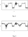
- Fig 2 shows estimated results of the side slip angle according to the present invention.
- Fig. 3 shows side slip angles as measured with expensive tools according to the prior art. As can be seen, the side slip angle obtained with the method 100 is very accurate, yet can be obtained with much less expensive hardware.
- Fig. 4 shows a vehicle 300 from above depicting a coordinate system with an x, y and z (towards the viewer) axis.
- the vehicle has 4 wheels on two axes.
- Fig. 5 shows a vehicle 300 according to the invention, which is steered at least partially automatically with an inventive method and/or comprising a steering unit that runs an inventive computer progam product.
Landscapes
- Engineering & Computer Science (AREA)
- Chemical & Material Sciences (AREA)
- Combustion & Propulsion (AREA)
- Transportation (AREA)
- Mechanical Engineering (AREA)
- Steering Control In Accordance With Driving Conditions (AREA)
Priority Applications (1)
| Application Number | Priority Date | Filing Date | Title |
|---|---|---|---|
| EP23209606.5A EP4556348A1 (de) | 2023-11-14 | 2023-11-14 | Verfahren zum bereitstellen einer seitenrutschwinkelkorrektur und zum zumindest teilweise automatischen lenken eines fahrzeugs, computerprogrammprodukt, computerlesbares speichermedium und fahrzeug |
Applications Claiming Priority (1)
| Application Number | Priority Date | Filing Date | Title |
|---|---|---|---|
| EP23209606.5A EP4556348A1 (de) | 2023-11-14 | 2023-11-14 | Verfahren zum bereitstellen einer seitenrutschwinkelkorrektur und zum zumindest teilweise automatischen lenken eines fahrzeugs, computerprogrammprodukt, computerlesbares speichermedium und fahrzeug |
Publications (1)
| Publication Number | Publication Date |
|---|---|
| EP4556348A1 true EP4556348A1 (de) | 2025-05-21 |
Family
ID=88833969
Family Applications (1)
| Application Number | Title | Priority Date | Filing Date |
|---|---|---|---|
| EP23209606.5A Pending EP4556348A1 (de) | 2023-11-14 | 2023-11-14 | Verfahren zum bereitstellen einer seitenrutschwinkelkorrektur und zum zumindest teilweise automatischen lenken eines fahrzeugs, computerprogrammprodukt, computerlesbares speichermedium und fahrzeug |
Country Status (1)
| Country | Link |
|---|---|
| EP (1) | EP4556348A1 (de) |
Citations (6)
| Publication number | Priority date | Publication date | Assignee | Title |
|---|---|---|---|---|
| US5243524A (en) * | 1990-03-15 | 1993-09-07 | Honda Giken Kogyo Kabushiki Kaisha | Method and apparatus for controlling a vehicle and accounting for side-slip angle |
| US20090248250A1 (en) * | 2008-03-31 | 2009-10-01 | Yoshiyuki Yasui | Steering control device for vehicle |
| US8160780B2 (en) | 2007-12-13 | 2012-04-17 | Hyundai Motor Japan R&D Center, Inc. | System and method for keeping a vehicle in a lane |
| US20130261899A1 (en) * | 2012-03-28 | 2013-10-03 | Robert Bosch Gmbh | Non-linear compensation controller for active steering system in a vehicle |
| US11364895B2 (en) | 2019-08-14 | 2022-06-21 | Xiamen King Long United Automotive Industry Co., Ltd. | Yaw motion control method for four-wheel distributed vehicle |
| CN116534121A (zh) * | 2023-05-12 | 2023-08-04 | 吉林大学 | 一种基于模型预测的四轮转向车辆稳定性控制方法 |
-
2023
- 2023-11-14 EP EP23209606.5A patent/EP4556348A1/de active Pending
Patent Citations (7)
| Publication number | Priority date | Publication date | Assignee | Title |
|---|---|---|---|---|
| US5243524A (en) * | 1990-03-15 | 1993-09-07 | Honda Giken Kogyo Kabushiki Kaisha | Method and apparatus for controlling a vehicle and accounting for side-slip angle |
| EP0446903B1 (de) | 1990-03-15 | 1996-06-26 | Honda Giken Kogyo Kabushiki Kaisha | Gerät zum automatischen Fahren |
| US8160780B2 (en) | 2007-12-13 | 2012-04-17 | Hyundai Motor Japan R&D Center, Inc. | System and method for keeping a vehicle in a lane |
| US20090248250A1 (en) * | 2008-03-31 | 2009-10-01 | Yoshiyuki Yasui | Steering control device for vehicle |
| US20130261899A1 (en) * | 2012-03-28 | 2013-10-03 | Robert Bosch Gmbh | Non-linear compensation controller for active steering system in a vehicle |
| US11364895B2 (en) | 2019-08-14 | 2022-06-21 | Xiamen King Long United Automotive Industry Co., Ltd. | Yaw motion control method for four-wheel distributed vehicle |
| CN116534121A (zh) * | 2023-05-12 | 2023-08-04 | 吉林大学 | 一种基于模型预测的四轮转向车辆稳定性控制方法 |
Non-Patent Citations (3)
| Title |
|---|
| ANWAR S ED - ANONYMOUS: "Predictive Yaw Stability Control of a Brake-By-Wire Equipped Vehicle via Eddy Current Braking", AMERICAN CONTROL CONFERENCE, 2007. ACC '07, IEEE, PISCATAWAY, NJ, USA, 9 July 2007 (2007-07-09), pages 2308 - 2313, XP031215373, ISBN: 978-1-4244-0988-4 * |
| JIZHENG LIU ET AL: "Sideslip angle estimation of ground vehicles: a comparative study", IET CONTROL THEORY AND APPLICATIONS, THE INSTITUTION OF ENGINEERING AND TECHNOLOGY, GB, vol. 14, no. 20, 12 March 2021 (2021-03-12), pages 3490 - 3505, XP006105829, ISSN: 1751-8644, DOI: 10.1049/IET-CTA.2020.0516 * |
| MILANI SINA ET AL: "Smart Autodriver Algorithm for Real-Time Autonomous Vehicle Trajectory Control", IEEE TRANSACTIONS ON INTELLIGENT TRANSPORTATION SYSTEMS, IEEE, PISCATAWAY, NJ, USA, vol. 23, no. 3, 21 October 2020 (2020-10-21), pages 1984 - 1995, XP011902505, ISSN: 1524-9050, [retrieved on 20220309], DOI: 10.1109/TITS.2020.3030236 * |
Similar Documents
| Publication | Publication Date | Title |
|---|---|---|
| EP1574386B1 (de) | Stabilitätsregelungssystem eines Fahrzeuges | |
| CN101298256B (zh) | 电动助力转向装置及其控制方法 | |
| KR960000248B1 (ko) | 자동차의 운동제어장치 | |
| US9815449B2 (en) | Driving support control apparatus for vehicle | |
| CN107085424A (zh) | 用于自动驾驶的预瞄横向控制 | |
| EP2626264A1 (de) | Bewegungssteuersystem für ein Fahrzeug basierend auf Ruckinformation | |
| JP4491400B2 (ja) | 車両タイヤ状態検出方法および車両タイヤ状態検出装置 | |
| CN101837781A (zh) | 用于自动车道对正或换道的控制系统的基于模型的预测控制 | |
| US20080015754A1 (en) | System for estimating and compensating for lateral disturbances using controlled steering and braking | |
| US9180880B2 (en) | Driving force control system for vehicle | |
| CN104417603B (zh) | 转向控制设备和方法 | |
| US10752285B2 (en) | Apparatus and method for controlling rotation of vehicle in consideration of slip | |
| CN201235814Y (zh) | 电动助力转向装置 | |
| Chaichaowarat et al. | Optimal control for steady state drifting of RWD vehicle | |
| Chaichaowarat et al. | Dynamics and simulation of RWD vehicles drifting at steady state using BNP-MNC tire model | |
| EP4556348A1 (de) | Verfahren zum bereitstellen einer seitenrutschwinkelkorrektur und zum zumindest teilweise automatischen lenken eines fahrzeugs, computerprogrammprodukt, computerlesbares speichermedium und fahrzeug | |
| Glaser et al. | Lateral wind force and torque estimation for a driving assistance | |
| JP4862422B2 (ja) | 車両の状態推定及び制御装置 | |
| Šolc et al. | Testing direct yaw moment control using a scaled car and a roadway simulator | |
| JP4862423B2 (ja) | 車両の状態推定及び制御装置 | |
| Bevan | Development of a vehicle dynamics controller for obstacle avoidance | |
| JP5918303B2 (ja) | 加加速度情報を用いて運動制御される車両 | |
| JP3629916B2 (ja) | 前2軸車両のスタビリティファクタ導出方法及び目標ヨーレイト設定方法 | |
| Lu | Dynamic Control of Formula: Towards Driverless | |
| Gidlewski et al. | Concept of the automatization of dangerous driving manoeuvres |
Legal Events
| Date | Code | Title | Description |
|---|---|---|---|
| PUAI | Public reference made under article 153(3) epc to a published international application that has entered the european phase |
Free format text: ORIGINAL CODE: 0009012 |
|
| STAA | Information on the status of an ep patent application or granted ep patent |
Free format text: STATUS: THE APPLICATION HAS BEEN PUBLISHED |
|
| AK | Designated contracting states |
Kind code of ref document: A1 Designated state(s): AL AT BE BG CH CY CZ DE DK EE ES FI FR GB GR HR HU IE IS IT LI LT LU LV MC ME MK MT NL NO PL PT RO RS SE SI SK SM TR |
|
| STAA | Information on the status of an ep patent application or granted ep patent |
Free format text: STATUS: REQUEST FOR EXAMINATION WAS MADE |
|
| 17P | Request for examination filed |
Effective date: 20251010 |