EP4556545A1 - Kohlenwasserstoff-verbundmischung mit verbesserten eigenschaften aus kunststoffabfällen - Google Patents
Kohlenwasserstoff-verbundmischung mit verbesserten eigenschaften aus kunststoffabfällen Download PDFInfo
- Publication number
- EP4556545A1 EP4556545A1 EP23209743.6A EP23209743A EP4556545A1 EP 4556545 A1 EP4556545 A1 EP 4556545A1 EP 23209743 A EP23209743 A EP 23209743A EP 4556545 A1 EP4556545 A1 EP 4556545A1
- Authority
- EP
- European Patent Office
- Prior art keywords
- compartment
- hydrocarbon compound
- compound mixture
- vapour
- compartments
- Prior art date
- Legal status (The legal status is an assumption and is not a legal conclusion. Google has not performed a legal analysis and makes no representation as to the accuracy of the status listed.)
- Withdrawn
Links
Images
Classifications
-
- C—CHEMISTRY; METALLURGY
- C10—PETROLEUM, GAS OR COKE INDUSTRIES; TECHNICAL GASES CONTAINING CARBON MONOXIDE; FUELS; LUBRICANTS; PEAT
- C10G—CRACKING HYDROCARBON OILS; PRODUCTION OF LIQUID HYDROCARBON MIXTURES, e.g. BY DESTRUCTIVE HYDROGENATION, OLIGOMERISATION, POLYMERISATION; RECOVERY OF HYDROCARBON OILS FROM OIL-SHALE, OIL-SAND, OR GASES; REFINING MIXTURES MAINLY CONSISTING OF HYDROCARBONS; REFORMING OF NAPHTHA; MINERAL WAXES
- C10G1/00—Production of liquid hydrocarbon mixtures from oil-shale, oil-sand, or non-melting solid carbonaceous or similar materials, e.g. wood, coal
- C10G1/002—Production of liquid hydrocarbon mixtures from oil-shale, oil-sand, or non-melting solid carbonaceous or similar materials, e.g. wood, coal in combination with oil conversion- or refining processes
-
- C—CHEMISTRY; METALLURGY
- C08—ORGANIC MACROMOLECULAR COMPOUNDS; THEIR PREPARATION OR CHEMICAL WORKING-UP; COMPOSITIONS BASED THEREON
- C08J—WORKING-UP; GENERAL PROCESSES OF COMPOUNDING; AFTER-TREATMENT NOT COVERED BY SUBCLASSES C08B, C08C, C08F, C08G or C08H
- C08J11/00—Recovery or working-up of waste materials
- C08J11/04—Recovery or working-up of waste materials of polymers
- C08J11/10—Recovery or working-up of waste materials of polymers by chemically breaking down the molecular chains of polymers or breaking of crosslinks, e.g. devulcanisation
- C08J11/12—Recovery or working-up of waste materials of polymers by chemically breaking down the molecular chains of polymers or breaking of crosslinks, e.g. devulcanisation by dry-heat treatment only
-
- C—CHEMISTRY; METALLURGY
- C10—PETROLEUM, GAS OR COKE INDUSTRIES; TECHNICAL GASES CONTAINING CARBON MONOXIDE; FUELS; LUBRICANTS; PEAT
- C10B—DESTRUCTIVE DISTILLATION OF CARBONACEOUS MATERIALS FOR PRODUCTION OF GAS, COKE, TAR, OR SIMILAR MATERIALS
- C10B47/00—Destructive distillation of solid carbonaceous materials with indirect heating, e.g. by external combustion
- C10B47/18—Destructive distillation of solid carbonaceous materials with indirect heating, e.g. by external combustion with moving charge
-
- C—CHEMISTRY; METALLURGY
- C10—PETROLEUM, GAS OR COKE INDUSTRIES; TECHNICAL GASES CONTAINING CARBON MONOXIDE; FUELS; LUBRICANTS; PEAT
- C10B—DESTRUCTIVE DISTILLATION OF CARBONACEOUS MATERIALS FOR PRODUCTION OF GAS, COKE, TAR, OR SIMILAR MATERIALS
- C10B47/00—Destructive distillation of solid carbonaceous materials with indirect heating, e.g. by external combustion
- C10B47/28—Other processes
- C10B47/32—Other processes in ovens with mechanical conveying means
- C10B47/44—Other processes in ovens with mechanical conveying means with conveyor-screws
-
- C—CHEMISTRY; METALLURGY
- C10—PETROLEUM, GAS OR COKE INDUSTRIES; TECHNICAL GASES CONTAINING CARBON MONOXIDE; FUELS; LUBRICANTS; PEAT
- C10B—DESTRUCTIVE DISTILLATION OF CARBONACEOUS MATERIALS FOR PRODUCTION OF GAS, COKE, TAR, OR SIMILAR MATERIALS
- C10B53/00—Destructive distillation, specially adapted for particular solid raw materials or solid raw materials in special form
- C10B53/07—Destructive distillation, specially adapted for particular solid raw materials or solid raw materials in special form of solid raw materials consisting of synthetic polymeric materials, e.g. tyres
-
- C—CHEMISTRY; METALLURGY
- C10—PETROLEUM, GAS OR COKE INDUSTRIES; TECHNICAL GASES CONTAINING CARBON MONOXIDE; FUELS; LUBRICANTS; PEAT
- C10G—CRACKING HYDROCARBON OILS; PRODUCTION OF LIQUID HYDROCARBON MIXTURES, e.g. BY DESTRUCTIVE HYDROGENATION, OLIGOMERISATION, POLYMERISATION; RECOVERY OF HYDROCARBON OILS FROM OIL-SHALE, OIL-SAND, OR GASES; REFINING MIXTURES MAINLY CONSISTING OF HYDROCARBONS; REFORMING OF NAPHTHA; MINERAL WAXES
- C10G1/00—Production of liquid hydrocarbon mixtures from oil-shale, oil-sand, or non-melting solid carbonaceous or similar materials, e.g. wood, coal
- C10G1/10—Production of liquid hydrocarbon mixtures from oil-shale, oil-sand, or non-melting solid carbonaceous or similar materials, e.g. wood, coal from rubber or rubber waste
-
- C—CHEMISTRY; METALLURGY
- C10—PETROLEUM, GAS OR COKE INDUSTRIES; TECHNICAL GASES CONTAINING CARBON MONOXIDE; FUELS; LUBRICANTS; PEAT
- C10G—CRACKING HYDROCARBON OILS; PRODUCTION OF LIQUID HYDROCARBON MIXTURES, e.g. BY DESTRUCTIVE HYDROGENATION, OLIGOMERISATION, POLYMERISATION; RECOVERY OF HYDROCARBON OILS FROM OIL-SHALE, OIL-SAND, OR GASES; REFINING MIXTURES MAINLY CONSISTING OF HYDROCARBONS; REFORMING OF NAPHTHA; MINERAL WAXES
- C10G9/00—Thermal non-catalytic cracking, in the absence of hydrogen, of hydrocarbon oils
- C10G9/34—Thermal non-catalytic cracking, in the absence of hydrogen, of hydrocarbon oils by direct contact with inert preheated fluids, e.g. with molten metals or salts
- C10G9/36—Thermal non-catalytic cracking, in the absence of hydrogen, of hydrocarbon oils by direct contact with inert preheated fluids, e.g. with molten metals or salts with heated gases or vapours
-
- C—CHEMISTRY; METALLURGY
- C10—PETROLEUM, GAS OR COKE INDUSTRIES; TECHNICAL GASES CONTAINING CARBON MONOXIDE; FUELS; LUBRICANTS; PEAT
- C10G—CRACKING HYDROCARBON OILS; PRODUCTION OF LIQUID HYDROCARBON MIXTURES, e.g. BY DESTRUCTIVE HYDROGENATION, OLIGOMERISATION, POLYMERISATION; RECOVERY OF HYDROCARBON OILS FROM OIL-SHALE, OIL-SAND, OR GASES; REFINING MIXTURES MAINLY CONSISTING OF HYDROCARBONS; REFORMING OF NAPHTHA; MINERAL WAXES
- C10G2300/00—Aspects relating to hydrocarbon processing covered by groups C10G1/00 - C10G99/00
- C10G2300/10—Feedstock materials
- C10G2300/1003—Waste materials
-
- C—CHEMISTRY; METALLURGY
- C10—PETROLEUM, GAS OR COKE INDUSTRIES; TECHNICAL GASES CONTAINING CARBON MONOXIDE; FUELS; LUBRICANTS; PEAT
- C10G—CRACKING HYDROCARBON OILS; PRODUCTION OF LIQUID HYDROCARBON MIXTURES, e.g. BY DESTRUCTIVE HYDROGENATION, OLIGOMERISATION, POLYMERISATION; RECOVERY OF HYDROCARBON OILS FROM OIL-SHALE, OIL-SAND, OR GASES; REFINING MIXTURES MAINLY CONSISTING OF HYDROCARBONS; REFORMING OF NAPHTHA; MINERAL WAXES
- C10G2300/00—Aspects relating to hydrocarbon processing covered by groups C10G1/00 - C10G99/00
- C10G2300/20—Characteristics of the feedstock or the products
- C10G2300/30—Physical properties of feedstocks or products
- C10G2300/304—Pour point, cloud point, cold flow properties
Definitions
- the invention relates to a hydrocarbon compound mixture with improved properties that is obtained by a process of converting plastic waste materials into liquid hydrocarbon compound mixtures.
- Plastic materials have significant advantages such as chemical and mechanical stability and low weight, and the properties of the plastic materials can be adjusted during the production process to meet the requirements of a wide variety of applications.
- Today plastic materials are usually made from fossil feedstocks and a significant part of the plastics produced are still designed for a single use.
- European Commission published on its website in 2023
- almost 26 million tons of plastic waste is generated in Europe every year and the European Commission is addressing the negative impact of such plastic waste generation in several policies.
- US20160024390A1 discloses a dual stage pyrolysis apparatus for the continuous conversion of hydrocarbon materials to condensable, non-condensable and solid hydrocarbon materials.
- the apparatus comprises at least one extruder capable of providing shear force and heat and having three or more treatment zones, a continuous process thermal kiln reactor, said extruder and said kiln reactor being in fluid communication, and means for transporting the hydrocarbon materials through the apparatus.
- the hydrocarbon materials are maintained within zones for a range of defined temperature and residence times, wherein the extruder has at least three zones, and the kiln reactor comprises at least two zones. During the process, waxes are removed from the reactor as solid materials.
- WO2019202546A1 discloses a pyrolysis plant for the thermal depolymerization of plastic material.
- the plant includes a closed vessel of a reactor to which a feeder for the supply of the plastic material is connected and where the reactor vessel has an output of gaseous products resulting from the depolymerisation, has a mechanical mixer and an output for the removal of unevaporated heavier fractions.
- WO2022013712A1 discloses a method for pyrolysis of waste material.
- the method comprises providing a screw arrangement adapted to supply heat to the mass by mechanical shear, providing a reactor after the screw arrangement, adapted to supply heat to the mass in the absence of oxygen by heating the reactor wall, heating the mass to an exit temperature and increasing the pressure to an exit pressure in the screw arrangement, thermally degrading the mass in the reactor, wherein the mass is brought into an extreme condition at the exit temperature and exit pressure by the screw arrangement, such that during the pressure drop pyrolysis occurs, thereby forming gaseous hydrocarbons within the connecting element.
- US20210189252A1 and US20210189254A1 disclose a circular economic approach for the recycling of polyethylene and polypropylene waste plastics through oil refinery operations.
- Typical pyrolysis oils were obtained from commercial sources and their properties are summarized. These pyrolysis samples were prepared from waste plastics containing mostly polyethylene and polypropylene via thermal decomposition in a pyrolysis reactor at around 400-600 °C and the 99.5% Final Boiling Point of such samples are between 888°F and 1079°F corresponding to about 475°C and 581°C.
- a hydrocarbon compound mixture having a cloud point of ⁇ 15°C and being transparent in layers of 40 mm in thickness at 20°C in accordance with the relevant standard test method for measuring the cloud point, obtained by a process of converting plastic waste materials into liquid hydrocarbon compound mixtures.
- hydrocarbon compound mixture having a cloud point of ⁇ 15°C, measured according to ASTM D2500-23, and being transparent in layers of 40 mm in thickness at 20°C in accordance with that ASTM D2500-23 standard test method for measuring the cloud point, obtained by a process of converting plastic waste materials into liquid hydrocarbon compound mixtures.
- a high cloud point is an indicator of fractions within the hydrocarbon compound mixture that have a high molecular weight and/or long carbon chains such as waxes, and that tend to precipitate from the oily hydrocarbon compound mixture.
- the precipitation of such fractions can lead to pollution of storage, transport and conveyor equipment at the production plant, the transport for further processing and at the facilities of the oil refinery or steam cracker and it is desired to limit such pollution to a minimum.
- the hydrocarbon compound mixture has a cloud point of ⁇ 5°C, even more preferably of ⁇ -5°C, still more preferably of ⁇ -15°C, and still more preferably of ⁇ -25°C.
- hydrocarbon compound mixture wherein the hydrocarbon mixture has a final boiling point for 99.5wt% of the mixture of ⁇ 430°C, preferably ⁇ 420°C, even more preferably ⁇ 410°C, and still further preferably ⁇ 400°C.
- hydrocarbon compound mixture wherein the hydrocarbon mixture has a final boiling point (measured according to ASTM D2887-22) for 99.5wt% of the mixture of ⁇ 430°C, preferably ⁇ 420°C, even more preferably ⁇ 410°C, and still further preferably ⁇ 400°C.
- the hydrocarbon compound mixture according to this invention can be obtained by applying a process comprising certain process steps.
- the hydrocarbon compound mixture is obtained by a process comprising the following steps:
- the plastic waste material is initially heated and compressed in a densifying unit.
- the applied heat is causing a part of the unwanted gases and water to evaporate and decreases the viscosity of the plastic waste materials so that it is starting to melt.
- step A) the plastic waste material is then further heated until it is substantially melted. During that step further unwanted gases are evaporated.
- the optimal temperature applied during step A) depends on the kind of plastics that are processed and the kind and amount of unwanted gases present in the plastic waste material.
- the final temperature of step A) is set to a range from 220 to 340°C, preferably to 240 to 320°C.
- the temperature ranges mentioned above refer to the temperature at the end of this process step, when the material has reached its final temperature.
- the material entering the unit in which step A) When the material is entering the unit in which step A) is performed it can still have a lower temperature resulting from a previous preparation step and the material is heated up within the unit in which step A) is performed until the temperature set point is achieved.
- the material entering the unit in which step A) is performed can e.g. have a temperature between 150 and 200°C.
- the viscosity of the mixture is further decreased so that the mixture can be easier conveyed to the compartments in which the actual pyrolysis is performed. Furthermore, it prevents particular corrosive gases and/or air to enter the compartments in which the pyrolysis occurs.
- the melted plastic waste material undergoes a controlled decomposition or pyrolysis reaction.
- that pyrolysis reaction is performed in an apparatus having at least 2 different compartments. That means that the compartments are physically segregated so that the process conditions, in particular the temperature, can be precisely and independently controlled in each of the compartments.
- the first compartment is usually set to a temperature that is higher than the temperature in the second compartment.
- the first compartment shall mean the compartment into which the material after having undergone step A) is first entering.
- the higher temperature compared with the temperature applied in process step A) is causing the melted plastic material to start a fast pyrolysis reaction.
- the vapour pressure the vapor resulting from this pyrolysis reaction is continuously leaving the first compartment through an interconnection with the second compartment in which it is further processed.
- the vapour leaving the first compartment is introduced in the oil phase of the second compartment through a pipe that is dipped into the oil phase.
- the apparatus in which the pyrolysis steps occur is further equipped with an interconnection between the second and the first compartment that allows liquid such as the oil phase present in the second compartment moving back to the first compartment. That back flow of liquid is preferably performed in a controlled manner, e.g. controlled by valves within such interconnection, so that the oil level in the second compartment, the liquid level in the first compartment and the residence time in the 2 compartments can be controlled.
- the process steps applied according to this invention allow the operators to vary several process parameters in a way that the throughput through the apparatus and the properties of the resulting hydrocarbon compound mixtures can be precisely adjusted.
- the feed rate to the first compartment, the temperatures in the first and the second compartment and the back flow of liquid material from the second compartment to the first compartment are relevant variables that permit the production of the desired product quality.
- an inventive hydrocarbon compound mixture is obtained by a process, wherein the vapor temperature within the first compartment is set to a range between ⁇ 400°C and ⁇ 500°C, preferably between ⁇ 420°C and ⁇ 460°C.
- an inventive hydrocarbon compound mixture is obtained by a process, wherein the vapour temperature within the second compartment is set to a range between ⁇ 350°C and ⁇ 450°C, preferably between ⁇ 370°C and ⁇ 400°C.
- the fine-tuning of such temperature settings depends on the composition of the plastic waste material, the desired throughput through the apparatus and the back flow rate of liquid from the second to the first compartment and a skilled operator can optimize these process variables by measuring the desired quality of the final hydrocarbon compound mixture as a function of small variations of the process variables.
- the pyrolysis reaction in the first compartment is performed under harsher conditions so that more decomposition occurs in the first compartment compared with the second compartment. That means that the first compartment is usually set to a residence time and temperature condition that allow for an efficient decomposition of the bulk of the plastic waste materials. The residence time and temperature settings in the second compartment are then adjusted to the fine-tuning of the pyrolysis reaction so that the decomposition can reach the desired degree and the quality of the final hydrocarbon compound mixture can be optimized.
- an inventive hydrocarbon compound mixture is obtained by a process, wherein the vapour temperature within the first compartment is at least 10°C higher than the second compartment, preferably at least 20°C higher and even more preferably at least 30°C higher.
- the residence time is an important parameter to control the quality of the final hydrocarbon compound mixture.
- the residence time of the pyrolysis mixture in the first compartment is in particular controlled by the feed of raw material into the compartment, by the back flow ratio of oil from the second compartment and by the temperature applied in the first compartment. It is often desired to obtain a degree of decomposition that is high enough to obtain homogeneous liquid hydrocarbon compound mixtures, but the degree of decomposition should not be too high because the further cracking in an oil refinery crude unit or a steam cracker can often be performed under energetically advantageous conditions and can in particular be fine-tuned for obtaining the desired end-product of a refinery or steam cracker. It is an advantage of the apparatus and the process steps as described in this invention to provide the flexibility to obtain a variety of high-quality hydrocarbon compound mixtures by variations of the above-mentioned process conditions, including the residence time in the compartments.
- an inventive hydrocarbon compound mixture is obtained by a process, wherein the average residence time of the reaction mixture in the first compartment is between 30 and 240 minutes, preferably between 60 and 180 minutes, and even more preferably between 90 and 150 minutes.
- an inventive hydrocarbon compound mixture is obtained by a process, wherein the average residence time of the reaction mixture in the second compartment is between 30 and 240 minutes, preferably between 60 and 180 minutes, and even more preferably between 90 and 150 minutes.
- the above-mentioned average residence times are the residence times that can be calculated from the feed of liquid or molten plastic waste material obtained from the previous process step into the respective first or following compartment and the volume occupied by liquid within that respective compartment.
- the residence time can be determined based on the feed, without adding the back flow from the second compartment, into the first compartment and the volume occupied by liquid within that first compartment.
- an inventive hydrocarbon compound mixture is obtained by a process, wherein the apparatus comprises 3 different compartments and the third compartment having a lower vapour temperature than the second compartment, and the second and the third compartments having one or more interconnections to allow vapour formed in the second compartment to move to the third compartments, and to allow liquid formed in the third compartment moving back to the second compartment.
- the options for controlling the process described in the section related to the interconnections between the first and the second compartment apply, mutatis mutandis, also to the interconnections between the third and the second compartment.
- the third compartment permits further fine-tuning of the final product specification and quality and allows the production of an even more homogeneous hydrocarbon compound mixture with the desired cloud points and final boiling points.
- the third compartment can be designed as one or more reflux condensers, in which, depending on the temperature settings, part or all of the vapour leaving the second compartment is condensed and is permitted to return to the second compartment for a continuation of the pyrolysis reaction, until that pyrolysis reaction has advanced to a stage that a part of the vapour entering the one or more reflux condensers will not condense anymore but will leave the reflux condenser(s) and is allowed to proceed to the condensation step C).
- the 2 or more compartments can be arranged in several ways or geometries, horizontally or vertically, or even with a certain physical distance from each other.
- an inventive hydrocarbon compound mixture is obtained by a process, wherein all of the at least 2 compartments are arranged in a way that the first compartment is located at the lowest level and the consecutive compartment(s) is/are located above the respective prior compartment.
- step C the vapour that has passed the cooling means of the last of the compartments is condensed to obtain a liquid hydrocarbon mixture.
- That cooling can be achieved by standard cooling means such as shell and tube heat exchangers.
- an inventive hydrocarbon compound mixture is obtained by a process, wherein the exit temperature of the unit in which the condensation of step C) is taking place is set to a value below 180°C.
- step C) is also possible to arrange step C) as a cascaded condensation step if a fractionation of the condensate is desired. In such case, additional condensers cooling to different temperatures can be used.
- the final exit temperature of the condensers that are involved in process step C) is preferably set to ambient temperature such as between 20 and 30°C.
- an inventive hydrocarbon compound mixture is obtained by a process, wherein the condensation of process step C) is taking place in more than one condensing units and at least 2 of such condensing units are operated at different temperatures.
- an inventive hydrocarbon compound mixture is obtained by a process, wherein the process by which it is obtained is a continuous process.
- the pyrolysis reaction requires a continuous supply of thermal energy
- a suitable energy source is important for an economic and efficient operation of the process described in this invention.
- the heating can be best achieved by electrical heating devices.
- electrical heating devices can be adjusted more precisely and faster than fuel-based and in particular syngas-based heating devices and that turned out to be a significant advantage for the fine-tuning of the temperature settings in the different compartments, in particular in the first compartment in which the major part of the pyrolysis reaction is taking place and where the temperature cannot be additionally controlled by reflux condensers.
- an inventive hydrocarbon compound mixture is obtained by a process, wherein the first compartment is heated by an electrical heater.
- an inventive hydrocarbon compound mixture is obtained by a process, wherein the first and the second compartment are heated by an electrical heater.
- Some processes for the pyrolysis of plastic waste materials that are known in the art are trying to reduce the amount of waxes that can form during the pyrolysis process by separating them in an early stage of the process and to recover such waxes as solid products.
- further waxes can be formed during later stages of the pyrolysis process or may not be sufficiently removed. Consequently, such processes are usually producing pyrolysis oils with a significant amount of waxes, with the consequence that the final pyrolysis oils are not fully homogeneous, in particular at lower temperatures.
- the hydrocarbon compound mixtures according to this invention are obtained by a process that is designed not to separate waxes as a side stream but to crack such substances in a controlled manner to a degree, that they do not have any significant effect on the final hydrocarbon compound mixtures. For the same reason also the yield of the final hydrocarbon compound mixtures is higher than it would be if the waxes would be removed as solids and not be further pyrolyzed in the process.
- an inventive hydrocarbon compound mixture is obtained by a process, wherein the process by which it is obtained does not comprise a step for physically removing waxes from any of the pyrolysis compartments.
- the plastic waste materials from which the inventive hydrocarbon compound mixtures can be produced can be any plastic waste as e.g. defined by the United Nations Environment Programme (UNEP), i.e. any discarded plastic (organic, or synthetic, material derived from polymers, resins or cellulose) generated by any industrial process, or by consumers. Discarded plastic generated by industrial processes are often well defined and may contain less undesired side materials. Discarded plastic waste generated by consumers does usually comprise a variety of plastic polymers of different composition and contain more undesired side materials such as food residues. Since the collection systems for plastic waste vary from country to country or even from community to community, the composition of the plastic waste materials that are intended to be pyrolyzed can be different. After the collection of the plastic waste the plastic waste is usually pretreated and separated from metals, paper and other components. According to the instant invention any of such common pretreated plastic waste material can be processed into the inventive hydrocarbon compound mixtures.
- UDP United Nations Environment Programme
- an inventive hydrocarbon compound mixture is obtained by a process, wherein the plastic waste materials are post-consumer mixed plastic waste materials.
- the hydrocarbon compound mixtures obtained according to this invention can represent one element of a circular economy concept for the recycling of plastic polymers into new plastic polymers. According to such a circular economy concept, after their use the plastic polymers will be collected and converted to the inventive hydrocarbon compound mixtures by applying the process steps described in this invention disclosure.
- the hydrocarbon compound mixtures can then be fed into the crude unit of an oil refinery in which it may be hydrotreated and further cracked to generate suitable feedstock e.g. for a steam cracker, or can be fed directly into a steam cracker, in which new monomers are created which can be processed to new plastic polymers.
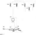
- the plastic waste material is fed to a densifier 101, e.g. by means of conveyor belts.
- the densifier compresses the plastic waste material.
- the compression may be achieved by one or more screw conveyors comprising the densifier 101.
- the compression heats the residual polymer product due to friction effects.
- the heating may result in that at least some of the polymer product melts, but the heating is sufficiently low so that no substantial chemical degradation takes place. However, the heating may cause generation of some water vapour from the polymer product which is advantageously removed.
- the densifier may be configured so that the residual polymer product is heated up to a temperature within a range from 150 to 200°C.
- the compressed, heated and possibly partially molten polymer product mixture is then transferred to the degasser 102, e.g. via a heated pipe, so that the partially molten polymer mixture will not solidify within the pipe.
- the degasser 102 comprises a screw conveyor to move the residual polymer product from an inlet to a degasser exit.
- the degasser 102 comprises a heater such as an electrical heater for heating the polymer product to a final temperature within a range from 240 to 330 °C.
- a preferred exit temperature of the melted residual polymer product at the degasser exit may be a temperature within a range from 250 to 270 °C, preferably from 255 to 265 °C.
- the heating in the degasser 102 causes vaporization of substantially all water content along with other undesired volatiles as well as non-condensable gasses. Such undesired volatiles could contain undesired vapours such as corrosive gasses and vapours. The removal of such undesired volatiles may enable the use of less corrosion resistant materials for the downstream components of the apparatus such as the pyrolysis reactor and may thus represent not only a procedural but also an economic benefit.
- calcium oxide or other alkaline substances may be fed either to the densifier 101 or to the degasser 102.
- the addition of such alkaline substances can neutralize the acidic gases that are generated during the pyrolysis, in particular of chlorine containing polymers such as polyvinyl chloride.
- the pyrolysis reactor 103 In the displayed apparatus, the pyrolysis reactor 103, the first compartment of the process described in this invention, is arranged in an inclined way so that the level of the liquid mixture within the reactor is not reaching the upside end of the reactor.
- the pyrolysis reactor 103 comprises 2 reactor screw conveyors for moving and mixing the liquid mixture and to transport solid residues, in particular carbon black that is generated during the pyrolysis reaction, towards an outlet.
- the pyrolysis reactor 103 is heated by a heater such as an electrical heater for heating the reaction mixture to a temperature within a range from ⁇ 400 to ⁇ 500 °C to generate pyrolysis vapour.
- the temperature in the pyrolysis reactor may vary between the liquid phase at the entrance to the reactor, the liquid phase at the upper end of the reactor and the vapour phase.
- the temperature ranges mentioned above indicate the temperature of the vapour phase within the reactor and that applies to all embodiments of this invention described within this specification. Even the vapour temperature within a compartment may not always be constant because vapour with a higher temperature from a previous compartment may need some time to adjust to the new temperature settings applied in the consecutive compartment. In that case the vapour temperature at the exit of the respective compartment shall be used for the purpose of determining the temperature ranges described in this specification.
- reaction mixture Upon heating, the reaction mixture is gradually pyrolyzed and a vapor comprising hydrocarbon compounds is formed and is leaving the pyrolysis reactor towards the second compartment, in this case an oil reactor in which again a liquid oil phase and a vapour phase are present.
- the oil reactor 104 is a tank arranged to separate the pyrolysis vapour received from the pyrolysis reactor 103 into vapour components and liquid components.
- the oil reactor 104 may comprise an agitator for mixing the content.
- the pyrolysis vapours enter the oil reactor 104 via a nozzle in the top and/or by a dip pipe into the liquid phase of the tank.
- the tank temperature is adjustable within a temperature range of ⁇ 350 and ⁇ 450°C.
- a temperature control system may be provided to control the tank temperature according to a desired temperature setpoint.
- the temperature in the oil reactor 104 can be controlled e.g. by an electrical heater.
- the oil reactor 104 and the pyrolysis reactor 103 are interconnections that permits a controlled backflow from the oil reactor 104 to the pyrolysis reactor 103.
- a fraction of the liquid in the oil reactor can be further exposed to the pyrolysis conditions in the pyrolysis reactor 103.
- the temperature may vary between the oil phase and the vapour phase and the temperatures indicated above are referring to the temperature within the vapour phase.
- the oil reactor 104 comprises two separator outlets for transferring the vapour generated in the oil reactor 104 to two reflux condensers 105a, 105b via respective pipes.
- the same pipes will lead condensed liquids from the reflux condensers 105a, 105b back to the oil reactor 104 via liquid outlets of the reflux condensers. These liquid outlets therefore also function as vapour inlets.
- the reflux condensers 105a, 105b are arranged to condense at least a fraction of the vapour components from the oil reactor 104 into liquid components.
- the apparatus is equipped with two reflux condensers to allow the further operation of the apparatus while one of the reflux condensers can be shut down for cleaning or maintenance.
- the two reflux condensers may be configured as shell and tube heat exchangers with pyrolysis vapours on the tube side and thermal oil for controlling the temperature on the shell side.
- the vapour leaving the reflux condensers 105a and 105b move through pipe connections to the condensers 106a and 106b in which the vapour is condensed to a liquid pyrolysis oil.
- the condensers are again duplicated to allow maintenance and cleaning of one condenser while the apparatus can continue to operate.
- the condensers can be designed as common shell and tube heat exchangers. If it is desired to fractionate the pyrolysis oil, the condensers 106a and 106b can be set to a temperature in a range of e.g.
- ⁇ 130 and ⁇ 180°C and the vapour that pass the condensers at that temperature range can be further condensed in a condenser 107 set to a lower temperature to obtain a lighter fraction of the pyrolysis products such as naphtha.
- an inventive process was found, wherein the process is a continuous process, and wherein the quality of the hydrocarbon compound mixture is controlled by applying the following steps:
- Suitable methods for measuring a quality parameter that correlate with the amount of such high molecular weight compounds in the hydrocarbon compound mixture that have a boiling point ⁇ 410°C are, by way of example, the ASTM D2500-23 method for measuring the cloud point, or the ASTM2887-22 method for measuring the final boiling point, but according to this specific embodiment also other methods can be used that may result in a similar quality determination.
- a cloud point measurement such as ASTM D2500-23
- the transparency of the final hydrocarbon compound mixture does not meet the transparency requirement of that method
- the vapour temperature within the first pyrolysis compartment can first be increased or decreased until the transparency requirement is met and then further until the desired quality parameter threshold is achieved.
- a desired quality parameter threshold can be, e.g., a cloud point of ⁇ 15°C, but also other quality parameter thresholds corresponding to a quality specification established by the manufacturer of the hydrocarbon compound mixture can be used.
Landscapes
- Chemical & Material Sciences (AREA)
- Engineering & Computer Science (AREA)
- Oil, Petroleum & Natural Gas (AREA)
- Organic Chemistry (AREA)
- Chemical Kinetics & Catalysis (AREA)
- Materials Engineering (AREA)
- Life Sciences & Earth Sciences (AREA)
- General Chemical & Material Sciences (AREA)
- Thermal Sciences (AREA)
- Wood Science & Technology (AREA)
- Physics & Mathematics (AREA)
- Combustion & Propulsion (AREA)
- Health & Medical Sciences (AREA)
- Polymers & Plastics (AREA)
- Medicinal Chemistry (AREA)
- Sustainable Development (AREA)
- Production Of Liquid Hydrocarbon Mixture For Refining Petroleum (AREA)
- Separation, Recovery Or Treatment Of Waste Materials Containing Plastics (AREA)
Priority Applications (2)
| Application Number | Priority Date | Filing Date | Title |
|---|---|---|---|
| EP23209743.6A EP4556545A1 (de) | 2023-11-14 | 2023-11-14 | Kohlenwasserstoff-verbundmischung mit verbesserten eigenschaften aus kunststoffabfällen |
| PCT/EP2024/082118 WO2025104059A1 (en) | 2023-11-14 | 2024-11-13 | Hydrocarbon compound mixture with improved properties obtained from plastic waste materials |
Applications Claiming Priority (1)
| Application Number | Priority Date | Filing Date | Title |
|---|---|---|---|
| EP23209743.6A EP4556545A1 (de) | 2023-11-14 | 2023-11-14 | Kohlenwasserstoff-verbundmischung mit verbesserten eigenschaften aus kunststoffabfällen |
Publications (1)
| Publication Number | Publication Date |
|---|---|
| EP4556545A1 true EP4556545A1 (de) | 2025-05-21 |
Family
ID=88833817
Family Applications (1)
| Application Number | Title | Priority Date | Filing Date |
|---|---|---|---|
| EP23209743.6A Withdrawn EP4556545A1 (de) | 2023-11-14 | 2023-11-14 | Kohlenwasserstoff-verbundmischung mit verbesserten eigenschaften aus kunststoffabfällen |
Country Status (2)
| Country | Link |
|---|---|
| EP (1) | EP4556545A1 (de) |
| WO (1) | WO2025104059A1 (de) |
Citations (9)
| Publication number | Priority date | Publication date | Assignee | Title |
|---|---|---|---|---|
| WO1979000625A1 (en) * | 1978-02-15 | 1979-09-06 | Intenco Inc | Process for recovering carbon black and hydrocarbons from used tires |
| US6011187A (en) * | 1996-02-27 | 2000-01-04 | Mitsubishi Heavy Industries, Ltd. | Method and apparatus for reclaiming oil from waste plastic |
| US20110203968A1 (en) * | 2008-07-11 | 2011-08-25 | John Scheirs | Method of processing oil refining waste |
| US20160024390A1 (en) | 2012-02-15 | 2016-01-28 | Vadxx Energy LLC | Dual stage, zone-delineated pyrolysis apparatus |
| EP3260181A1 (de) * | 2016-06-23 | 2017-12-27 | SUEZ Groupe | Verfahren zur umwandlung von kunststoffen in brennstoff |
| WO2019202546A1 (en) | 2018-04-21 | 2019-10-24 | Daniska Vladimir | Method for thermic depolymerization of plastic material and device for its realization |
| US20210189254A1 (en) | 2019-12-23 | 2021-06-24 | Chevron U.S.A. Inc. | Circular economy for plastic waste to polypropylene and lubricating oil via refinery fcc and isomerization dewaxing units |
| US20210189252A1 (en) | 2019-12-23 | 2021-06-24 | Chevron U.S.A. Inc. | Circular economy for plastic waste to polyethylene and lubricating oil via crude and isomerization dewaxing units |
| WO2022013712A1 (en) | 2020-07-17 | 2022-01-20 | Cct International | Method for pyrolysis of waste material in an industrial process |
-
2023
- 2023-11-14 EP EP23209743.6A patent/EP4556545A1/de not_active Withdrawn
-
2024
- 2024-11-13 WO PCT/EP2024/082118 patent/WO2025104059A1/en active Pending
Patent Citations (9)
| Publication number | Priority date | Publication date | Assignee | Title |
|---|---|---|---|---|
| WO1979000625A1 (en) * | 1978-02-15 | 1979-09-06 | Intenco Inc | Process for recovering carbon black and hydrocarbons from used tires |
| US6011187A (en) * | 1996-02-27 | 2000-01-04 | Mitsubishi Heavy Industries, Ltd. | Method and apparatus for reclaiming oil from waste plastic |
| US20110203968A1 (en) * | 2008-07-11 | 2011-08-25 | John Scheirs | Method of processing oil refining waste |
| US20160024390A1 (en) | 2012-02-15 | 2016-01-28 | Vadxx Energy LLC | Dual stage, zone-delineated pyrolysis apparatus |
| EP3260181A1 (de) * | 2016-06-23 | 2017-12-27 | SUEZ Groupe | Verfahren zur umwandlung von kunststoffen in brennstoff |
| WO2019202546A1 (en) | 2018-04-21 | 2019-10-24 | Daniska Vladimir | Method for thermic depolymerization of plastic material and device for its realization |
| US20210189254A1 (en) | 2019-12-23 | 2021-06-24 | Chevron U.S.A. Inc. | Circular economy for plastic waste to polypropylene and lubricating oil via refinery fcc and isomerization dewaxing units |
| US20210189252A1 (en) | 2019-12-23 | 2021-06-24 | Chevron U.S.A. Inc. | Circular economy for plastic waste to polyethylene and lubricating oil via crude and isomerization dewaxing units |
| WO2022013712A1 (en) | 2020-07-17 | 2022-01-20 | Cct International | Method for pyrolysis of waste material in an industrial process |
Also Published As
| Publication number | Publication date |
|---|---|
| WO2025104059A1 (en) | 2025-05-22 |
Similar Documents
| Publication | Publication Date | Title |
|---|---|---|
| CN112538363B (zh) | 用于在延迟焦化器单元中共转化废塑料的方法和装置 | |
| CN114746530B (zh) | 从含塑料的废物和有机液体中裂解长链烃 | |
| US8674154B2 (en) | Apparatus and method for conducting thermolysis of plastic waste in continuous manner | |
| US12378476B2 (en) | Method for pyrolysing plastic material and a system therefor | |
| JP2019513180A (ja) | 石油生成物を製造するための方法、装置、コントローラ及びシステム | |
| KR20240128003A (ko) | 일정하지 않은 조성의 실질적 플라스틱 물질의 열분해 공정, 관련 반응기, 장치 및 수득한 생성물 | |
| CN118696107A (zh) | 用于生产适于闭环回收的热解油的热解工艺、相关设备、产品及其用途 | |
| EP4556545A1 (de) | Kohlenwasserstoff-verbundmischung mit verbesserten eigenschaften aus kunststoffabfällen | |
| CN119790120A (zh) | 热裂解塑料废物的方法 | |
| CN117545823A (zh) | 废塑料转化成烃的方法 | |
| US20250297164A1 (en) | Pyrolysis system for production of hydrocarbon compounds from residual plastic products | |
| NL2033861B1 (en) | System and Process for Degassing of Pyrolysis Plastics | |
| RU2796014C2 (ru) | Технологическая линия переработки вододисперсных полиизопреновых отходов | |
| NL2037149B1 (en) | Pyrolysis product composition comprising char particles | |
| WO2024218310A2 (en) | Advanced chemical recycling of mixed and pure waste plastics within a molten metal reactor | |
| EP4698609A2 (de) | Verbessertes chemisches recycling von gemischten und reinen kunststoffabfällen, optional innerhalb eines reaktors für geschmolzenes metall | |
| EP4599021A1 (de) | Gestufte wärmetauscher zum kracken von kohlenwasserstoffen | |
| CA3256225A1 (en) | A method for pyrolysing plastic material and a system therefor | |
| KR20250163939A (ko) | 유체 탄화수소를 열분해하기 위한 장치 및 방법 | |
| HK40077788B (zh) | 从含塑料的废物和有机液体中裂解长链烃 | |
| CA3268741A1 (en) | Staggered heat exchangers for cracking hydrocarbons | |
| CN118434827A (zh) | 用于将废塑料转化成化学品的方法 | |
| EP4669726A1 (de) | Verfahren und vorrichtung zur gewinnung von polymeröl aus einem strömungswiderstand |
Legal Events
| Date | Code | Title | Description |
|---|---|---|---|
| PUAI | Public reference made under article 153(3) epc to a published international application that has entered the european phase |
Free format text: ORIGINAL CODE: 0009012 |
|
| STAA | Information on the status of an ep patent application or granted ep patent |
Free format text: STATUS: THE APPLICATION HAS BEEN PUBLISHED |
|
| AK | Designated contracting states |
Kind code of ref document: A1 Designated state(s): AL AT BE BG CH CY CZ DE DK EE ES FI FR GB GR HR HU IE IS IT LI LT LU LV MC ME MK MT NL NO PL PT RO RS SE SI SK SM TR |
|
| RAP1 | Party data changed (applicant data changed or rights of an application transferred) |
Owner name: MAKEEN FIRST |
|
| STAA | Information on the status of an ep patent application or granted ep patent |
Free format text: STATUS: THE APPLICATION IS DEEMED TO BE WITHDRAWN |
|
| 18D | Application deemed to be withdrawn |
Effective date: 20251122 |