EP4556630A1 - Barrière routière avec protection pour motocyclistes - Google Patents
Barrière routière avec protection pour motocyclistes Download PDFInfo
- Publication number
- EP4556630A1 EP4556630A1 EP24212965.8A EP24212965A EP4556630A1 EP 4556630 A1 EP4556630 A1 EP 4556630A1 EP 24212965 A EP24212965 A EP 24212965A EP 4556630 A1 EP4556630 A1 EP 4556630A1
- Authority
- EP
- European Patent Office
- Prior art keywords
- longitudinal
- beams
- road barrier
- containment band
- oblong cross
- Prior art date
- Legal status (The legal status is an assumption and is not a legal conclusion. Google has not performed a legal analysis and makes no representation as to the accuracy of the status listed.)
- Pending
Links
Images


Classifications
-
- E—FIXED CONSTRUCTIONS
- E01—CONSTRUCTION OF ROADS, RAILWAYS, OR BRIDGES
- E01F—ADDITIONAL WORK, SUCH AS EQUIPPING ROADS OR THE CONSTRUCTION OF PLATFORMS, HELICOPTER LANDING STAGES, SIGNS, SNOW FENCES, OR THE LIKE
- E01F15/00—Safety arrangements for slowing, redirecting or stopping errant vehicles, e.g. guard posts or bollards; Arrangements for reducing damage to roadside structures due to vehicular impact
- E01F15/02—Continuous barriers extending along roads or between traffic lanes
- E01F15/04—Continuous barriers extending along roads or between traffic lanes essentially made of longitudinal beams or rigid strips supported above ground at spaced points
- E01F15/0407—Metal rails
- E01F15/0423—Details of rails
- E01F15/043—Details of rails with multiple superimposed members; Rails provided with skirts
Definitions
- the present invention relates to a road barrier with motorcyclists protection.
- the present invention relates to a programmed-deformation, discontinuous road barrier with motorcyclists protection.
- road barriers are fixed structures that are placed along the lateral edge of the carriageway and are adapted to hold, within the carriageway, a car or other vehicle for transporting goods and/or persons of medium to large dimensions, which should accidentally impact against the same road barrier.
- guard-rails are basically made up of a series of supporting posts, which are made of metal and are driven into the ground in a substantially vertical position, one spaced side by side the other along the lateral edge of the carriageway; and of a series of ribbonlike cross-beams with a double- or triple-wave profile, which are made of metal, are fixed to the supporting posts in a horizontal position and one after the other, at a predetermined height above the ground, and are butt-fixed one to the other via special through bolts, so as to form a longitudinal retaining band, which extends seamlessly along the lateral edge of the carriageway.
- the ribbonlike cross-beams with double- or triple- wave profiles are fastened to the supporting posts so that the longitudinal retaining band is roughly at the same height as the bumpers of cars and other vehicles for transporting goods and/or persons that travel on the roads.
- the supporting posts and ribbonlike cross-beams with a double- or triple- wave profile are specifically structured and dimensioned to retain, within the carriageway, a car or other vehicle for transporting goods and/or persons of medium to large dimensions, which might accidentally impact against the road barrier in the event of an accident.
- supporting posts and/or double- or triple-wave ribbonlike cross-beams sometimes have sharp edges that unfortunately can be lethal for the motorcyclist impacting at high speed.
- a road barrier with cyclists protection which comprises, in addition to the traditional horizontal ribbonlike cross-beams with a double- or triple- wave profile, also a series of horizontal ribbonlike cross-beams with a fretted profile, which are arranged horizontally, spaced beneath the longitudinal containment band formed by the horizontal ribbonlike cross-beams with double- or triple-wave profile, and are fastened to the supporting posts of the road barrier by means of spacers with programmed-deformation structure, which deform in the event of impact by the motorcyclist.
- a road barrier comprising, in addition to the traditional horizontal ribbonlike cross-beams with a double- or triple- wave profile, a series of straight metal section-bars with omega profile, which are arranged horizontally and one after the other, spaced beneath the longitudinal containment band formed by the horizontal ribbonlike cross-beams with a double- or triple- wave profile, and are fixed directly to the supporting posts of the road barrier by means of metal strips.
- Aim of the present invention is to realise a discontinuous-type road barrier, which offers better protection to motorcyclists in the event of an accident and which is, at the same time, easy and cheap to install.
- a road barrier with motorcyclists protection as defined in Claim 1 and preferably, though not necessarily, in any one of the claims dependent thereon.
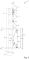
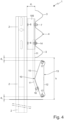
- number 1 denotes, as a whole, a road barrier adapted to be installed long the lateral edge of the carriageway, with the function of holding, within the carriageway, a car or other vehicle for transporting goods and/or persons of medium to large dimensions, which should accidentally impact against the same road barrier 1.
- the road barrier 1 is adapted to be firmly anchored to the ground P along the lateral edge of the carriageway, and comprises: a series of supporting posts 2 preferably made of metallic material, which are fixed/adapted to be firmly fixed to the ground P in a substantially vertical position, one spaced side by side the other along the lateral edge of the carriageway; and a series of oblong cross-beams 3 preferably made of metallic material, which are firmly fixed to the supporting posts 2 in a substantially horizontal position and one after the other, at a predetermined height above the ground, so as to form a longitudinal containment band 4 that extends along the lateral edge of the carriageway roughly parallel to the ground P.
- supporting posts 2 are preferably substantially straight and are preferably structured to be driven into the ground in a substantially vertical position.
- the road barrier 1 could also be a bridge-side road barrier or similar.
- the supporting posts 2 could be fixed directly to the reinforced concrete, advantageously by means of anchor plates and/or anchor bolts placed at the lower ends of the supporting posts 2.
- the oblong cross-beams 3, on the other hand, are preferably substantially rectilinear and are preferably fixed rigidly to the lateral side of the supporting posts 2 preferably via the interposition of special connecting brackets 5 advantageously made of metallic material, which are preferably structured so as to keep the oblong cross-beams 3 roughly grazing the supporting posts 2.
- the connecting brackets 5 are preferably structured so as to keep the oblong cross-beams 3 at a nominal distance d 1 from the supporting posts 2 less than or equal to 3-4 cm (centimetres).
- connection brackets 5 are preferably fixed cantilevered on the lateral side of the supporting posts 2 at a predetermined height above the ground, advantageously by means of one and more pass-through anchoring bolts 6, and the oblong cross-beams 3 are fixed directly to the connection brackets 5 advantageously by means of one and more pass-through anchoring bolts 7.
- the oblong cross-beams 3 are preferably butt-fixed to one another so as to form a longitudinal retaining band 4, which extends seamlessly along the lateral edge of the carriageway.
- the oblong cross-beams 3 preferably have ribbonlike structure.
- the oblong and ribbonlike cross-beams 3 preferably overlap to one another at their respective ends, and are preferably rigidly fixed to one another by means of at least one or, more conveniently, a plurality of pass-through connecting bolts 8, which are adapted to tighten, one against the other, the ends of two consecutive oblong cross-beams 3.
- the supporting posts 2 preferably have an overall length ranging between 1 and 2 m (metres) and/or are preferably made of steel.
- the supporting posts 2 preferably consist of straight metal section-bars advantageously with a substantially U- or C- shaped cross-section.
- these straight metal section-bars may also have an IPE, HE, sigma, etc. profile.
- the supporting posts 2 are moreover driven into the ground so that the protruding section has an overall length ranging between 80 and 130 cm (centimetres), and more conveniently equal to about 100 cm.
- Oblong cross-beams 3 on the other hand, have an overall length preferably ranging between 4 and 6 m (metres) and more conveniently equal to about 5 m (metres), and are preferably made of steel.
- the oblong cross-beams 3 preferably consist of ribbonlike straight metal section-bars advantageously with a double- or triple- wave profile.
- the longitudinal containment band 4 therefore, preferably has a double- or triple- wave profile.
- the nominal thickness of the metal sheet forming these straight and ribbonlike metal section-bars with a double or triple-wave profile moreover ranges between 2 and 6 mm and is advantageously equal to about 3 mm (millimetres).
- oblong cross-beams 3 furthermore have a nominal width ranging between 45 and 55 cm (centimetres) and more conveniently equal to about 50 cm.
- the oblong cross-beams 3 are preferably placed at a minimum height h from ground advantageously ranging between 40 and 50 cm (centimetres), and more conveniently equal to about 45 cm.
- the longitudinal retaining band 4 is located at a minimum height h from ground preferably ranging between 40 and 50 cm (centimetres), and more conveniently equal to about 45 cm.
- the connecting brackets 5, on the other hand preferably consist of ribbonlike metal slats which are bent substantially in the shape of a ⁇ (omega) and are advantageously arranged with the two ends abutting on the side of the supporting post 2.
- the ribbonlike slats are moreover made of steel.
- the road barrier 1 is furthermore provided with a longitudinal motorcyclists-protection structure 10, which extends roughly parallel to the ground P beneath the longitudinal retaining band 4, and is adapted to prevent the motorcyclist, in event of a fall-off and subsequent sliding on the road surface, to accidentally go beyond the longitudinal retaining band 4 passing beneath the latter and possibly also to violently impacting against one or more supporting posts 2.
- a longitudinal motorcyclists-protection structure 10 which extends roughly parallel to the ground P beneath the longitudinal retaining band 4, and is adapted to prevent the motorcyclist, in event of a fall-off and subsequent sliding on the road surface, to accidentally go beyond the longitudinal retaining band 4 passing beneath the latter and possibly also to violently impacting against one or more supporting posts 2.
- This longitudinal motorcyclist-protection structure 10 in particular is provided with a second longitudinal containment band, separate and distinct from the longitudinal containment band 4, which extends more or less parallel to the ground P spaced beneath the main longitudinal containment band 4, and is supported directly by the longitudinal containment band 4.
- this second longitudinal containment band is moreover spaced from the supporting posts 2.
- the longitudinal containment band of the longitudinal motorcyclists-protection structure 10 is rigidly fixed/attached to the longitudinal containment band 4 above.
- the longitudinal containment band of the longitudinal motorcyclists-protection structure 10 hangs rigidly below the main longitudinal containment band 4.
- longitudinal containment band of the longitudinal motorcyclists-protection structure 10 is preferably also supported substantially exclusively by the longitudinal containment band 4.
- the longitudinal containment band of the longitudinal motorcyclists-protection structure 10 extends roughly parallel to the main longitudinal containment band 4 and/or to the ground P, while remaining at a distance d 2 from the main longitudinal containment band 4 preferably greater than or equal to 1 cm (centimetres) and/or lower than or equal to 20 cm (centimetres).
- the longitudinal containment band of the longitudinal motorcyclists-protection structure 10 moreover extends roughly parallel to the main longitudinal containment band 4 and/or the ground P, while remaining at a maximum distance d 3 from the ground P preferably greater than or equal to 2 cm (centimetres) and/or lower than or equal to 15 cm (centimetres).
- the longitudinal motorcyclist-protection structure 10 preferably comprises: a series of supporting arms 11 preferably made of metallic material, which are firmly fixed to the longitudinal containment band 4, or rather to the oblong cross-beams 3, and extend cantilevered downwards one parallel to and spaced apart from the other, up to arrive at predetermined distance from the ground P below advantageously ranging between 4 and 10 cm (centimetres); and a second series of oblong cross-beams 12 preferably made of metallic material, which are firmly fixed on the supporting arms 11 in a substantially horizontal position and one following the other at a predetermined height above the ground, so as to form a second longitudinal containment band 13, which extends more or less parallel to the ground P, roughly beneath the longitudinal containment band 4.
- the width and/or the stiffness of the longitudinal retaining band 13 is/are moreover lower than that of the longitudinal retaining band 4.
- the supporting arms 11 are preferably substantially rectilinear and preferably extend cantilevered from the main longitudinal retaining band 4, or rather from the oblong cross-beams 3, in a substantially vertical direction.
- the upper end of the supporting arms 11 is preferably structured in so as to be rigidly fastened to the longitudinal retaining band 4, or rather to the oblong cross-beams 3, by means of at least one pass-through anchoring bolt 14.
- the lower end of the supporting arms 11 is bent towards the carriageway, i.e. it is bent towards the side opposite to the supporting posts 2.
- the lower end of the supporting arms 11 is inclined with respect to the vertical by an angle preferably ranging between 15° and 25°.
- the oblong cross-beams 12 are preferably substantially straight, and are preferably rigidly fixed to the lower ends of the various supporting arms 11.
- the oblong cross-beams 12 are preferably located beside the lower ends of the various supporting arms 11, and are preferably fixed in rigid manner to the various supporting arms 11 via the interposition of special connecting brackets 15 advantageously made of metallic material, which preferably have a programmed-deformation structure and are preferably structured so as to keep the oblong cross-beams 12 suspended almost grazing the ground P.
- the connecting brackets 15 are preferably fixed in rigid manner to the lower ends of the supporting arms 11 advantageously via at least one pass-through anchoring bolt 16, and the oblong cross-beams 12 are fixed directly to the connecting brackets 15 advantageously by means of one and more pass-through anchoring bolts 17.
- the oblong cross-beams 12 are preferably butt-fixed one to the other so as to form a longitudinal retaining band 13, which extends seamlessly along the lateral edge of the carriageway.
- the oblong cross-beams 12 preferably have a ribbonlike structure.
- the oblong and ribbonlike cross-beams 12 preferably overlap ton one another at their respective ends, and are preferably fixed in rigid manner to one another via at least one or, more conveniently, a plurality of pass-through connecting bolts 20, which are adapted to tighten one against the other the ends of two consecutive oblong cross-beams 12.
- the supporting arms 11 preferably have an overall length ranging between 40 and 60 cm (centimetres) and/or are preferably made of steel.
- the supporting arms 11 preferably consist of straight metal section-bars, advantageously with a substantially U- or C-shaped cross-section.
- the oblong cross-beams 12 on the other hand, have an overall length preferably shorter than that of oblong cross-beams 3 and advantageously ranging between 2 and 4 m (metres) and more conveniently equal to about 3,5 m (metres), and/or are preferably made of steel.
- the oblong cross-beams 12 are moreover arranged spaced beneath the oblong cross-beams 3, or rather beneath the main longitudinal retaining band 4, at a distance d 2 from the latters advantageously ranging between 2 and 4 cm (centimetres).
- the oblong cross-beams 12 preferably consist of straight and ribbonlike metal section-bars, advantageously with C-bent or C-curved lateral edges in order to give the correct stiffness/ flexibility to the element and to protect the motorcyclist's upper limbs from cuts.
- the oblong cross-beams 12 preferably have a substantially flat central band and two side bands, which flank the central band on opposite sides of the latter, and are bent or curved towards the supporting posts 2 behind.
- the nominal thickness of the metal sheet forming said metal ribbonlike section-bars with the later edges C-bent or C-curved is moreover lower than the nominal thickness of the metal ribbonlike section-bars with a doubleor triple- wave profile that form the oblong cross-beams 3.
- the nominal thickness of the metal sheet forming said metal ribbonlike section-bars with curved later edges preferably ranges between 2 and 4 mm, and is advantageously equal to about 3 mm (millimetres).
- oblong cross-beams 12 moreover have a width w ranging between 35 and 45 cm (centimetres) and more conveniently equal to about 40 cm.
- the oblong cross-beams 12 are moreover fixed to the supporting arms 11 advantageously via the interposition of connecting brackets 15, so as to extend substantially parallel to the ground P, at a distance d 2 from the oblong cross-beams 3 advantageously equal to about 3 cm (centimetres) and/or at a distance from the ground P advantageously equal to about 2 cm.
- the second longitudinal containment band 13 extends more or less parallel to the ground P, at a distance from the longitudinal containment band 4 advantageously equal to about 3 cm (centimetres) and/or at a distance from the ground P advantageously equal to about 2 cm (centimetres).
- the connecting brackets 15 preferably consist of ribbonlike metal slats, which are substantially V-bent, have their two ends rigidly fixed to the oblong cross-beam 12 preferably by means of a pair of pass-through bolts 17, and are finally fixed in rigid manner to the lower end of the supporting arms 11 near the central elbow preferably via the pass-through bolts 16.
- each V-bent ribbonlike metal slat is preferably arranged substantially coplanar to the corresponding supporting arm 11, and its two ends are fixed to the oblong cross-beam 12 one at the upper longitudinal edge and the other at the lower longitudinal edge of the oblong cross-beam 12.
- the connecting brackets 15 are preferably structured so as to connect the related supporting arm 11 simultaneously to both major longitudinal edges of the oblong cross-beam 12.
- the longitudinal retaining band 13 formed by the oblong cross-beams 12 is at a height from ground such that it is hit by the motorcyclist that, as a result of a fall-off, slides on the road surface up to impact against the road barrier 1.
- the supporting arms 11, the oblong cross-beams 12 and the connecting brackets 15 of the longitudinal motorcyclist-protection structure 10 are suitably shaped/dimensioned so as to plastically deform on impact of the motorcyclist against the longitudinal containment band 13.
- the longitudinal motorcyclist-protection structure 10 Since it is released from the supporting posts 2 that concur in forming the more rigid part of the road barrier 1, the longitudinal motorcyclist-protection structure 10 has a greater capacity to deform following the impact of the motorcyclist, thus more progressively absorbing the motorcyclist's kinetic energy.
- the kinetic energy of the motorcyclist is substantially entirely absorbed by the oblong cross-beams 12, the connecting brackets 15 and the supporting arms 11, which bend/deform substantially without involving the other (more rigid) metal parts of the road barrier 1.
- the longitudinal motorcyclists-protection structure 10 is made up of components that are relatively cheap to produce, with the savings this entails.
- the longitudinal motorcyclists-protection structure 10 is moreover suited for installation on traditional "guard-rail" type road barriers (i.e. having a longitudinal containment band advantageously with a double- or triple- wave profile) already installed along the carriageway, because it requires only minor structural modifications (the holes for the pass-through anchoring bolts 14) to the longitudinal containment band of the road barrier.
- guard-rail i.e. having a longitudinal containment band advantageously with a double- or triple- wave profile
- the oblong cross-beams 3 are fixed in rigid manner to the lateral side of the supporting posts 2 by the interposition of special spacer elements 105 advantageously made of metal material, which are structured so as to keep the oblong cross-beams 3 at a nominal distance d 1 from the supporting posts 2 greater than 5-6 cm (centimetres) and advantageously also lower than 80 cm (centimetres).
- the spacer elements 105 are preferably fixed cantilevered on the lateral side of the supporting posts 2 at a given height from ground, advantageously by means of at least one and more conveniently a plurality of pass-through connecting bolts 6, and the horizontal cross-beams 3 are fixed directly to the spacer elements 105 advantageously by means of at least one and more conveniently a plurality of pass-through connecting bolts 7.
- the spacer elements 105 moreover have a programmed-deformation structure.
- the spacer elements 105 are preferably dimensioned so as to keep the oblong cross-beams 3 at a nominal distance d 1 ranging between 8 and 12 cm (centimetres) and more conveniently equal to about 9-10 cm (centimetres).
- the spacer elements 105 could also be dimensioned so as to keep the oblong cross-beams 3 at a nominal distance d 1 from the supporting posts 2 greater than 12 cm (centimetres) and more conveniently equal to approximately 45-50 cm (centimetres).
- the spacer elements 105 preferably basically consist of rectilinear metal section-bars of given length and advantageously with a substantially U- or C-shaped cross-section, which are arranged in abutment on the lateral side of the supporting posts 2 preferably with their longitudinal axis substantially parallel to the longitudinal axis of the supporting post 2.
- the spacer elements 105 allow to arrange the longitudinal retaining band 13 at a greater distance from the supporting posts 2, thus increasing the deformation space of the longitudinal motorcyclist-protection structure 10.
- the upper ends of the supporting posts 2 could be connected to one another by horizontal stringers preferably made of metal material.
Landscapes
- Engineering & Computer Science (AREA)
- Architecture (AREA)
- Civil Engineering (AREA)
- Structural Engineering (AREA)
- Refuge Islands, Traffic Blockers, Or Guard Fence (AREA)
Applications Claiming Priority (1)
| Application Number | Priority Date | Filing Date | Title |
|---|---|---|---|
| IT102023000024426A IT202300024426A1 (it) | 2023-11-17 | 2023-11-17 | Barriera stradale con protezione per motociclisti |
Publications (1)
| Publication Number | Publication Date |
|---|---|
| EP4556630A1 true EP4556630A1 (fr) | 2025-05-21 |
Family
ID=89897890
Family Applications (1)
| Application Number | Title | Priority Date | Filing Date |
|---|---|---|---|
| EP24212965.8A Pending EP4556630A1 (fr) | 2023-11-17 | 2024-11-14 | Barrière routière avec protection pour motocyclistes |
Country Status (2)
| Country | Link |
|---|---|
| EP (1) | EP4556630A1 (fr) |
| IT (1) | IT202300024426A1 (fr) |
Citations (5)
| Publication number | Priority date | Publication date | Assignee | Title |
|---|---|---|---|---|
| EP1455020A1 (fr) | 2003-03-06 | 2004-09-08 | Profil R | Dispositif de fixation d'un écran de protection pour glissières de sécurité |
| DE202005009943U1 (de) * | 2005-06-22 | 2005-09-01 | SGGT Straßenausstattungen GmbH | Schutzeinrichtung zur Anordnung neben einer Fahrbahn |
| EP2088247A2 (fr) | 2008-02-05 | 2009-08-12 | Marcegaglia Buildtech S.R.L | Dispositif de sécurité pour motocyclistes, particulièrement pour l'application aux barrières de sécurité en bordure de voie |
| EP2400061A2 (fr) * | 2010-06-22 | 2011-12-28 | Señalizaciones Villar, S.a. | Structures de protection latérale routière |
| WO2021048453A1 (fr) * | 2019-09-10 | 2021-03-18 | Jose Luis Arroyo Fernandez | Dispositif de protection pour glissières de sécurité |
-
2023
- 2023-11-17 IT IT102023000024426A patent/IT202300024426A1/it unknown
-
2024
- 2024-11-14 EP EP24212965.8A patent/EP4556630A1/fr active Pending
Patent Citations (5)
| Publication number | Priority date | Publication date | Assignee | Title |
|---|---|---|---|---|
| EP1455020A1 (fr) | 2003-03-06 | 2004-09-08 | Profil R | Dispositif de fixation d'un écran de protection pour glissières de sécurité |
| DE202005009943U1 (de) * | 2005-06-22 | 2005-09-01 | SGGT Straßenausstattungen GmbH | Schutzeinrichtung zur Anordnung neben einer Fahrbahn |
| EP2088247A2 (fr) | 2008-02-05 | 2009-08-12 | Marcegaglia Buildtech S.R.L | Dispositif de sécurité pour motocyclistes, particulièrement pour l'application aux barrières de sécurité en bordure de voie |
| EP2400061A2 (fr) * | 2010-06-22 | 2011-12-28 | Señalizaciones Villar, S.a. | Structures de protection latérale routière |
| WO2021048453A1 (fr) * | 2019-09-10 | 2021-03-18 | Jose Luis Arroyo Fernandez | Dispositif de protection pour glissières de sécurité |
Also Published As
| Publication number | Publication date |
|---|---|
| IT202300024426A1 (it) | 2025-05-17 |
Similar Documents
| Publication | Publication Date | Title |
|---|---|---|
| US4838523A (en) | Energy absorbing guard rail terminal | |
| EP1741833B1 (fr) | Barrière de sécurité en métal avec d'un système continu métallique de protection pour des motocyclistes | |
| JP2001513160A (ja) | 自動車道路のガードレール用安全バリヤー末端部 | |
| US10597834B2 (en) | Crash barrier system with different intervals | |
| JP2014077230A (ja) | 防護柵および防護柵の設置方法 | |
| US9051699B2 (en) | Pedestrian and vehicle barrier | |
| KR20090003941U (ko) | 도로 중앙분리대의 완충장치 | |
| EP4556630A1 (fr) | Barrière routière avec protection pour motocyclistes | |
| CN115698432B (zh) | 碰撞缓冲器 | |
| KR101379607B1 (ko) | 차량 방호 울타리 | |
| GB2433285A (en) | Vehicle restraining fence for a building | |
| CN211340578U (zh) | 一种带辅助缓冲刹车多级降速的安全护栏 | |
| GB2450352A (en) | Wire rope vehicle restraining fence | |
| KR200391835Y1 (ko) | 복합형 차량 방호책 | |
| CN215518549U (zh) | 一种公路护栏防撞气囊装置 | |
| EP1561863A1 (fr) | Glissière de sécurité | |
| CN205276175U (zh) | 护栏单元和护栏 | |
| US7100903B1 (en) | Impact barrier system | |
| CZ350995A3 (en) | Crash-barrier shock absorber | |
| CN113356112A (zh) | 一种公路护栏防撞气囊装置 | |
| KR200422841Y1 (ko) | 충격 흡수용 연결브라켓 | |
| EP2746461B1 (fr) | Support de barrière de sécurité | |
| RU2856646C1 (ru) | Дорожное фронтальное ограждение | |
| KR101181429B1 (ko) | 충격흡수가드레일 | |
| EP2053166A1 (fr) | Bande de protection pour chaussée |
Legal Events
| Date | Code | Title | Description |
|---|---|---|---|
| PUAI | Public reference made under article 153(3) epc to a published international application that has entered the european phase |
Free format text: ORIGINAL CODE: 0009012 |
|
| STAA | Information on the status of an ep patent application or granted ep patent |
Free format text: STATUS: THE APPLICATION HAS BEEN PUBLISHED |
|
| AK | Designated contracting states |
Kind code of ref document: A1 Designated state(s): AL AT BE BG CH CY CZ DE DK EE ES FI FR GB GR HR HU IE IS IT LI LT LU LV MC ME MK MT NL NO PL PT RO RS SE SI SK SM TR |
|
| STAA | Information on the status of an ep patent application or granted ep patent |
Free format text: STATUS: REQUEST FOR EXAMINATION WAS MADE |
|
| 17P | Request for examination filed |
Effective date: 20251120 |
|
| RIN1 | Information on inventor provided before grant (corrected) |
Inventor name: FALLARINO, EZIO Inventor name: TUFO, STEFANO Inventor name: DOGO, MARIO |