EP4556632A2 - Fachwerksystem und verfahren zur verwendung davon für offshore-plattformen - Google Patents
Fachwerksystem und verfahren zur verwendung davon für offshore-plattformen Download PDFInfo
- Publication number
- EP4556632A2 EP4556632A2 EP25168141.7A EP25168141A EP4556632A2 EP 4556632 A2 EP4556632 A2 EP 4556632A2 EP 25168141 A EP25168141 A EP 25168141A EP 4556632 A2 EP4556632 A2 EP 4556632A2
- Authority
- EP
- European Patent Office
- Prior art keywords
- beams
- column
- disposed
- angle
- offshore vessel
- Prior art date
- Legal status (The legal status is an assumption and is not a legal conclusion. Google has not performed a legal analysis and makes no representation as to the accuracy of the status listed.)
- Pending
Links
Images


Classifications
-
- B—PERFORMING OPERATIONS; TRANSPORTING
- B63—SHIPS OR OTHER WATERBORNE VESSELS; RELATED EQUIPMENT
- B63B—SHIPS OR OTHER WATERBORNE VESSELS; EQUIPMENT FOR SHIPPING
- B63B3/00—Hulls characterised by their structure or component parts
- B63B3/14—Hull parts
- B63B3/48—Decks
-
- B—PERFORMING OPERATIONS; TRANSPORTING
- B63—SHIPS OR OTHER WATERBORNE VESSELS; RELATED EQUIPMENT
- B63B—SHIPS OR OTHER WATERBORNE VESSELS; EQUIPMENT FOR SHIPPING
- B63B3/00—Hulls characterised by their structure or component parts
- B63B3/14—Hull parts
- B63B3/26—Frames
- B63B3/32—Web frames; Web beams
-
- B—PERFORMING OPERATIONS; TRANSPORTING
- B63—SHIPS OR OTHER WATERBORNE VESSELS; RELATED EQUIPMENT
- B63B—SHIPS OR OTHER WATERBORNE VESSELS; EQUIPMENT FOR SHIPPING
- B63B1/00—Hydrodynamic or hydrostatic features of hulls or of hydrofoils
- B63B1/02—Hydrodynamic or hydrostatic features of hulls or of hydrofoils deriving lift mainly from water displacement
- B63B1/10—Hydrodynamic or hydrostatic features of hulls or of hydrofoils deriving lift mainly from water displacement with multiple hulls
- B63B1/107—Semi-submersibles; Small waterline area multiple hull vessels and the like, e.g. SWATH
-
- B—PERFORMING OPERATIONS; TRANSPORTING
- B63—SHIPS OR OTHER WATERBORNE VESSELS; RELATED EQUIPMENT
- B63B—SHIPS OR OTHER WATERBORNE VESSELS; EQUIPMENT FOR SHIPPING
- B63B35/00—Vessels or similar floating structures specially adapted for specific purposes and not otherwise provided for
- B63B35/44—Floating buildings, stores, drilling platforms, or workshops, e.g. carrying water-oil separating devices
- B63B35/4413—Floating drilling platforms, e.g. carrying water-oil separating devices
-
- B—PERFORMING OPERATIONS; TRANSPORTING
- B63—SHIPS OR OTHER WATERBORNE VESSELS; RELATED EQUIPMENT
- B63B—SHIPS OR OTHER WATERBORNE VESSELS; EQUIPMENT FOR SHIPPING
- B63B1/00—Hydrodynamic or hydrostatic features of hulls or of hydrofoils
- B63B1/02—Hydrodynamic or hydrostatic features of hulls or of hydrofoils deriving lift mainly from water displacement
- B63B1/10—Hydrodynamic or hydrostatic features of hulls or of hydrofoils deriving lift mainly from water displacement with multiple hulls
- B63B1/12—Hydrodynamic or hydrostatic features of hulls or of hydrofoils deriving lift mainly from water displacement with multiple hulls the hulls being interconnected rigidly
- B63B2001/128—Hydrodynamic or hydrostatic features of hulls or of hydrofoils deriving lift mainly from water displacement with multiple hulls the hulls being interconnected rigidly comprising underwater connectors between the hulls
-
- B—PERFORMING OPERATIONS; TRANSPORTING
- B63—SHIPS OR OTHER WATERBORNE VESSELS; RELATED EQUIPMENT
- B63B—SHIPS OR OTHER WATERBORNE VESSELS; EQUIPMENT FOR SHIPPING
- B63B3/00—Hulls characterised by their structure or component parts
- B63B3/14—Hull parts
- B63B2003/145—Frameworks, i.e. load bearing assemblies of trusses and girders interconnected at nodal points
-
- B—PERFORMING OPERATIONS; TRANSPORTING
- B63—SHIPS OR OTHER WATERBORNE VESSELS; RELATED EQUIPMENT
- B63B—SHIPS OR OTHER WATERBORNE VESSELS; EQUIPMENT FOR SHIPPING
- B63B35/00—Vessels or similar floating structures specially adapted for specific purposes and not otherwise provided for
- B63B35/44—Floating buildings, stores, drilling platforms, or workshops, e.g. carrying water-oil separating devices
- B63B2035/442—Spar-type semi-submersible structures, i.e. shaped as single slender, e.g. substantially cylindrical or trussed vertical bodies
Definitions
- Embodiments disclosed herein generally relate to a truss system for offshore platforms. More specifically, embodiments disclosed herein relate to geometry arrangements of the truss system to optimally distribute structural material to have a balance between structural weight and structural strength.
- offshore vessels such as platform supply vessels (PSV), offshore barges, anchor handling vessels, construction support vessels (CSV), drilling vessels, well intervention vessels, ice breaking vessels, crane vessels, cable laying vessels, seismic vessels, and firefighting vessels, are commonly used for various tasks, including, but not limited to, hydrocarbon exploration, hydrocarbon drilling and production, holding and transporting hydrocarbons, safety platforms, and heavy lift cranes.
- PSV platform supply vessels
- CSV construction support vessels
- drilling vessels such as well intervention vessels, ice breaking vessels, crane vessels, cable laying vessels, seismic vessels, and firefighting vessels
- the offshore vessels may typically have a topside structure to carry equipment payloads and environment loads. Further, stability columns such as pencil columns or rocket columns may be attached to the offshore vessels to stabilize the offshore vessels in a body of water.
- the topside structure may be a truss system to form the decks. A structural weight of the truss system needs to be reduced in order to maximize the pay load, while a structural strength criterion of the truss system must be satisfied for the harsh environment. In offshore environments, it is crucial to distribute the structural material efficiently in order to satisfy both the weight and strength requirements.
- the embodiments disclosed herein relate to a truss system.
- the truss system may include a plurality of beams. Each beam of the plurality of beams may have various cross-sectional sizes in a same plane. Additionally, the plurality of beams may have a geometric arrangement such that a structural weight at required strength level may be reduced to achieve optimal design.
- the embodiments disclosed herein relate to a lower deck for a topside truss system of an offshore vessel.
- the lower deck may include a plurality of beams distributed into four quadrants.
- the plurality of beams may extend in a direction parallel to an X-axis in a plane of the lower deck, parallel to a Y-axis in the plane, and angled at an acute or obtuse angle off the X-axis and the Y-axis.
- Each quadrant includes a first set of beams having a constant or varying cross-section, a second set of beams having a constant or varying cross-section, a third set of beams having a constant or varying cross-section, and a fourth set of beams having a constant or varying cross-section.
- the embodiments disclosed herein relate to an offshore vessel.
- the offshore vessel incudes a base having one or more support columns support members disposed thereon and a deck formed by a topside truss system supported by the one or more support columns support.
- the topside truss system includes an upper deck, a lower deck, and tubular members interconnecting the upper deck to the lower deck.
- the lower deck may have one or more quadrants with a first set of beams having a constant or varying cross-section, a second set of beams having a constant or varying cross-section, a third set of beams having a constant or varying cross-section, and a fourth set of beams having a constant or varying cross-section.
- corresponding corner beam members of the topside truss system are affixed to a top of the one or more support columns.
- disposing may be either directly disposing the first element on the second element, or indirectly disposing the first element on the second element.
- a first element may be directly disposed on a second element, such as by having the first element and the second element in direct contact with each other, or a first element may be indirectly disposed on a second element, such as by having a third element, and/or additional elements, disposed between the first and second elements.
- the term “attached to” or “coupled” or “coupled to” or “connected” or “connected to” may indicate establishing either a direct or indirect connection, and is not limited to either unless expressly referenced as such.
- embodiments disclosed herein are described with terms designating an offshore vessel in reference to a floating vessel, but any terms designating offshore structure (i.e., any platform or semi-submersible) should not be deemed to limit the scope of the disclosure.
- like or identical reference numerals are used in the figures to identify common or the same elements. The figures are not necessarily to scale and certain features and certain views of the figures may be shown exaggerated in scale for purposes of clarification.
- embodiments disclosed herein generally relate to a truss system for a topside structure of an offshore vessel.
- the truss system may be formed by a plurality of beams interconnected together. More specifically, a geometry of the beams may be in an arrangement such that a structural weight of the truss system and a structural strength of the truss system are optimized.
- the truss system may be disposed on columns of the offshore vessel.
- the truss system may be designed for use with onshore structures, such as oil derricks. Further, the truss system may be designed for use in any marine or land environment without departing from the scope of the present disclosure.
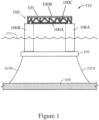
- the offshore vessel 113 may be a semi-submersible structure for oil and gas operations.
- a deck 101 sits above the surface of water 111.
- the deck 101 is typically used for drilling, production, or other operations and therefore operating equipment, personnel, and operation gear may be disposed thereon.
- the typical design load conditions for the offshore vessel 113 may be vertical bending moment, lateral shear, pry-squeeze, pitch connecting moment, and lateral acceleration.
- the deck 101 is formed by a topside truss system 100.
- the topside truss system 100 includes two or more deck levels (100A, 100B).
- an upper deck 100B is interconnected to a lower deck 100A by tubular members 100C.
- the topside truss system 100 may be supported by one or more support columns. As shown in this example, topside truss system 100 is disposed on support columns 106A and 106B and is therefore kept away from any large waves at the surface of the water 111. Support columns 106A and 106B are used to support topside truss system 100, but may also serve as storage. In addition, support columns 106A and 106B may be ballasted. A base, such as pontoon base 105, has the support columns 106A and 106B disposed thereon. The pontoon base 105 may be substantially rectangular in shape from a side view perspective, a plan view perspective, or both. In some embodiments, the topside truss system 100, the one or more support columns, and the pontoon base 105 may be one integrated system forming the offshore vessel 113.
- the offshore vessel 113 obtains buoyancy from ballasted pontoons or ballasted columns.
- the ballasted structure(s) ballasted pontoons or ballasted columns or both
- the semi-submersible 113 is anchored to the seabed 109 by anchor lines 107A and 107B.
- the anchor lines 107A and 107B may be wires, chains, or any other anchoring device known in the art that would keep the semi-submersible in a proper position with respect to the seabed 109.
- anchor lines may not be limited to only two lines as shown in this example.
- the offshore vessel 113 may be anchored by any number of anchor lines.
- the offshore vessel 113 may be adapted to be disposed on seabed 109 without the use of anchor lines 107A and 107B.
- the pontoon base 105 may be disposed on the seabed 109 and may be affixed to the seabed 109 using an affixing unit (not shown) to affix the pontoon base 105 and ultimately, the offshore vessel 113, to the seabed 109.
- the offshore vessel 113 may include four support columns 106A-106D extending upward from the pontoon base 105.
- the topside truss system 100 is disposed on the four support columns 106A-106D via corresponding corner beam members 108 of the topside truss system 100 for each of the four support columns 106A-106D.
- tubular members of the corresponding corner beam members 108 may be affixed to a top of the four support columns 106A-106D.
- the corresponding corner beam members 108 may be made of tubular members similar to the tubular members 100C interconnecting the upper deck 100B to the lower deck 100A.
- corresponding corner beam ends 100AB of the lower deck 100A are also affixed to the top of the four support columns 106A-106D a distance from the corresponding corner beam members 108.
- the support columns 106A-106D and the pontoon base 105 form a hull of the offshore vessel 113. As shown in Figure 1 , the support columns 106A-106D are disposed on the pontoon base 105. Also, in this case, the pontoon base 105 may be generally rectangular, triangular, and/or polygonal in shape and the support columns 106A-106D may be disposed near the corners of or at any position along the pontoon base 105.
- the position of the support columns 106A-106D are not limited to the corners of the pontoon base 105, as the support columns 106A-106D may be arranged in any other configuration with respect to the pontoon base 105.
- the number of support columns is not limited to four support columns 106A-106D, as shown, as there may be any number of support columns.
- a non-limiting example of the offshore vessel 113 may be described in U.S. Patent No. 9,145,190 , the entire teachings of which are incorporated herein by reference. It is further envisioned that offshore vessel 113 disclosed herein may be any semi-submersible in the art.
- each of the support columns 106A-106D includes lines 114 to illustrate a vertical position along the support columns 106A-106D in which the sides of the columns 106A-106D join across a rounded edge and may gradually transition to joining across a squared edge.
- regions 115 represent transition regions of the support columns 106A-106D in which a rounded corner may gradually transition to a squared corner. In this example, the transition regions extend along a portion of the support columns 106A-106D and terminate at the connection between the columns 106A-106D and the pontoon base 105.
- the pontoon base 105 may be generally rectangular, triangular, and/or polygonal in shape.
- one or more corners 209 of the pontoon base 105 may be chamfered (as shown).
- the pontoon base 105 may have one or more squared corners, one or more rounded corners, or any combination or alternative thereof (not shown).
- the interior 211 of the pontoon base 105 may have one or more chamfered corners 213 which may or may not correspond to the interior chamfered corners 209.
- the interior 211 of the pontoon base 105 may have one or more squared corners, one or more rounded corners, or any combination or alternative thereof (not shown).
- the cross-section 215 of the support columns 106A-106D may have five sides.
- One or more corners 217A, 217B, and 217C of the support columns 106A-106D may be squared, as shown.
- one or more edges 219A, 219B, and 219C of the support columns 106A-106D may be rounded, as shown.
- the one or more edges 219A, 219B, and 219C of t the support columns 106A-106D are rounded at one vertical end of the support column and squared at an opposite end of the support columns 106A-106D.
- one or more sides 221A, 221B, 221C, 221D, and 221E which correspond to cross-section 223, each represent a side of a support column.
- the corners or edges may be chamfered, rounded, squared, or any combination or alternative thereof.
- topside truss system 100 is illustrated as an outline. This is for example purposes only to better show how the topside truss system 100 is supported by the support columns 106A-106D on the pontoon base 105. As shown by Figure 2B , the corner beam members 108 of the topside truss system 100 are supported on the support columns 106A-106D.
- FIG. 2C a top view of one of the support columns is illustrated.
- one or more sides 303A, 303B, 303C, 303D of the support column 301 may be disposed with respect to one another, as shown.
- the first side 303A may be disposed at a first angle with respect to a second side 303B.
- the second side may be disposed at a second angle with respect to a third side 303C.
- the third side 303C may be disposed at a third angle with respect to a fourth side 303D.
- the first and second angle may be substantially right angles.
- the third angle may be a substantially obtuse angle.
- An example obtuse angle may be substantially 135 degrees, as shown. However, an obtuse angle may be anywhere between any angle greater than 90 degrees and less than 180 degrees. Additionally, an obtuse angle may be anywhere between 91 and 179 degrees, 100 and 170 degrees, 110 and 160 degrees, 120 and 150 degrees, or 130 and 140 degrees.
- the fourth side 303D may be disposed at a fourth angle with respect to a fifth side 303E.
- the fifth side 303E may be disposed at a fifth angle with respect to the first side 303A.
- the fourth angle may be a substantially obtuse angle and the fifth angle may be a substantially right angle.
- the one or more sides 303A, 303B, 303C, 303D of the support column 301 may be joined with rounded corners.
- the one or more sides 303A, 303B, 303C, 303D of the support column 301 may be joined with chamfered corners, squared corners, or any alternate thereof.
- the corners and corresponding sides of the support column are not limited to the above arrangement.
- one or more sides 403A, 403B, and 403C may extend outwardly along at least a portion of a support column 401.
- the outward extension, or “flaring,” as shown, may be provided for additional support at the base of the support column 401.
- the extension may be inward (not shown).
- one or more sides 503A, 503B, and 503C may extend outwardly (or inwardly) beginning at one end to another end of a support column 501.
- taper positions similar to Figure 2D do not exist along a portion of the length of the support column 501.
- the flaring spans the entire length of the support column 501. Accordingly, the taper position may be at either or both ends of the support column and the flaring may extend along the entirety of the support column 501.
- side 503B may not flare. Therefore, flaring may occur on any number of sides or none.
- one or more sides 603A, 603B, and 603C of a support column 601 may be a flared at the base.
- the side 603B also flares.
- the taper positions may be at any position along the length of the support column 601.
- one or more sides 703A, 703B, and 703C of a support column 701 may be flared at the base.
- taper positions similar to those described above in Figure 2F do not exist along any portion of the length of support column 701.
- the flaring spans the entire length of the support column 701. Accordingly, the taper position may be at either or both ends of the support column and the flaring may extend along the entirety of the support column 701.
- side 703B may or may not flare. Therefore, flaring may occur on any number of sides or none.
- a support column 801 has one or more chamfered sides 803A and 803B.
- the one or more chamfered sides 803A and 803B of the support column 801 may not be limited to an interior or an exterior with respect to a pontoon structure.
- the cross-section of a support column 801 may include one or more edges 805A, 805B, 805C, 805D, 805E, and 805F that correspond to one or more sides of the support column 801.
- the edges 805A, 805B, 805C, 805D, 805E, and 805F may be arranged as shown in Figure 2H .
- first edge 805A may be disposed at a first angle with respect to edge 805B.
- Edge 805B may be disposed at a second angle with respect to edge 805C.
- Edge 805C may be disposed at a third angle with respect to edge 805D.
- Edge 805D may be disposed at a fourth angle with respect to edge 805E.
- Edge 805E may be disposed at a fifth angle with respect to edge 805F.
- Edge 805F may be disposed at a sixth angle with respect to edge 805A.
- edges 805C and 805F may be chamfered and may correspond to chamfered sides 803A and 803B of the support column 801.
- the second and fifth angles may be substantially right angles and the first, third, fourth, and sixth angles may be substantially obtuse angles.
- An example obtuse angle may be substantially 135 degrees, as shown. However, an obtuse angle may be anywhere between any angle greater than 90 degrees and less than 180 degrees. Additionally, an obtuse angle may be anywhere between 91 and 179 degrees, 100 and 170 degrees, 110 and 160 degrees, 120 and 150 degrees, or 130 and 140 degrees.
- the six sided column may or may not include any or all of the features disclosed herein with respect to any of the embodiments of the multi-sided column as described above.
- the six sided column may include one or more of the following: one or more transition regions, one or more taper positions, and flaring.
- the six sided column may include one or more of the following: rounded edges or corners, squared edges or corners, and chamfered edges or corners.
- the upper deck 100B of the topside truss system 100 directly supports equipment used for drilling, production, or other operations and therefore operating equipment, personnel, and operation gear may be disposed thereon.
- the upper deck 100B may be formed by a plurality of beams (e.g., steel I-beams) in which the equipment fits within or upon.
- the periphery edge may be generally square, rectangular, and/or polygonal in shape.
- the upper deck 100B includes a first set of beams 110 and a second set of beams 112.
- the first set of beams 110 form the major truss rows.
- the second set of beams 112 may be orientated in a horizontal direction or in a transverse direction.
- the tubular members 100C space the upper deck 100B a distance from the lower deck 100A.
- the tubular members 100C may be angled to support the upper deck 100B on the lower deck 100A.
- the corner beam members 108 connect the topside truss system 100 to the support columns (see 106A-106D in Figure 2A-2H ).
- the lower deck 100A does not traverse into the corner beam members 108.
- the lower deck 100A may include two corresponding corner beam ends 100AB for each corner beam members 108. Each corner beam ends 100AB are also affixed to the top of the four support columns (see 106A-106D in Figure 2A-2H ) a distance from each corner beam members 108.
- the governing load cases may be simplified environmental loads combined with the inertial loads of the mass on the lower deck 100A and the upper deck 100B.
- the upper deck 100B and the lower deck 100A may be optimized to determine material distribution and voids of various shapes inside the deck to handle the governing load cases.
- the lower deck 100A may be formed by a plurality of beams (101a-104l) arranged in a plane P.
- the plane P may be a plane in which the lower deck 100A lays within.
- the plane P may be substantially parallel to the pontoon base (see 105 in Figures 1-2B ).
- the plurality of beams (101a-104l) may use a wide variety of beams in structural support operations.
- One skilled in the art will appreciate how the lower deck 100A may be able to achieve increased performance, decreased non-productive time (NPT), and improved equipment life and maintenance.
- NPT non-productive time
- the plurality of beams (101a-104l) of the lower deck 100A may include a first set of beams (101a-101d), a second set of beams (102a-102i), a third set of beams (103a-103m), and a fourth set of beams (104a-104l).
- Each set may have the same cross-section or varying cross-sections. It is understood that depending on the size, shape, and configuration of vessels (and its usage), different sizes, numbers and/or types of beam may be used.
- the first set of beams (101a-101d), the second set of beams (102a-102i), the third set of beams (103a-103m), and the fourth set of beams (104a-104l) may be connected together at their ends, midpoints, or along any length of the beams (101a-104l).
- the connection point between two beams may be end to end to and/or an end of one beam to a midpoint of another beam.
- one beam may be connected to two beams at corresponding midpoints of two beam. It is further envisioned that one beam may be connected to two beams at a corresponding midpoint of one beam to an end of another beam.
- One skilled in the art will appreciate how the connection point may be adjusted to meet loading requirements on the plurality of beams (101a-104l).
- the plurality of beams (101a-104d) may have a first geometry to optimally distribute structural material to have a balance between structural weight and structural strength.
- the first set of beams (101a-101d) may be arranged to have beams extending parallel to an X-axis X in the plane P, parallel to a Y-axis Y in the plane P, and angled at an acute or obtuse angle off the axis' X, Y.
- the second set of beams (102a-102i) may be arranged to have beams extending parallel to the X-axis X in the plane P, parallel to the Y-axis Y in the plane P, and angled at an acute or obtuse angle off the axis' X, Y.
- the third set of beams (103a-103m) may be arranged to have beams extending parallel to the X-axis X in the plane P, parallel to the Y-axis Y in the plane P, and angled at an acute or obtuse angle off the axis' X, Y.
- the fourth set of beams (104a-104d) may be arranged to have beams extending parallel to the X-axis X in the plane P and parallel to the Y-axis Y in the plane P.
- the configuration in Figure 4 of the lower deck 100A may include one or more quadrants of similar design.
- the lower deck 100A may have four quadrants as represented by dotted boxes 500A-500D.
- the lower deck 100A may also be symmetrical about a line of symmetry extending diagonally corner to corner.
- each quadrant 500A-500D includes the same number of beams from the first set of beams (101a-101d), the second set of beams (102a-102i), the third set of beams (103a-103m), and the fourth set of beams (104a-104d) in the same geometry.
- each quadrant 500A-500D has four beams from the first set of beams (101a-101d), nine beams from the second set of beams (102a-102i), thirteen beams from the third set of beams (103a-103m), and four beams from the fourth set of beams (104a-104d). It is further envisioned that the quadrants 500A-500D are symmetrical about longitudinal axis Lo and latitudinal axis LA. Alternatively, the lower deck 100A may be unsymmetrical at some local areas.
- the four beams of the first set of beams (101a-101d) have the geometry of a first beam 101a extending in the X-axis X with a second beam 101b acutely angled off the first beam 101a, and a third beam 101c extending in the Y-axis Y with a fourth beam 101d acutely angled off the third beam 101c.
- two beams 102a-102b of the second set of beams (102a-102i) extend further in the X-axis X and four beams 103a-103d of the third set of beams (103a-103m) extend further in the Y-axis Y.
- each quadrant 500A-500D share a first set of a beam 104a from the fourth set of beams (104a-104d), a beam 103l from the third set of beams (103a-103m), a beam 102h from the second set of beams (102a-102i), and a beam 104b from the fourth set of beams 104 extending in a line in the Y-axis Y and a second set of a beam 104c from the fourth set of beams (104a-104d), a beam 103m from the third set of beams (103a-103m), a beam 102i from the second set of beams (102a-102i), and a beam 104d from the fourth set of beams (104a-104d) extending in a line in the X-axis X.
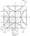
- the plurality of beams (101a-104l) may have a second geometry to optimally distribute structural material to have a balance between structural weight and structural strength.
- the first set of beams (101a-101d) may be arranged to have beams extending parallel to an X-axis X in the plane P, parallel to a Y-axis Y in the plane P, and angled at an acute or obtuse angle off the axis' X, Y.
- the second set of beams (102a-102h) may be arranged to have beams extending parallel to the X-axis X in the plane P, parallel to the Y-axis Y in the plane P, and angled at an acute or obtuse angle off the axis' X, Y.
- the third set of beams (103a-103g) may be arranged to have beams extending parallel to the X-axis X in the plane P, parallel to the Y-axis Y in the plane P, and angled at an acute or obtuse angle off the axis' X, Y.
- the fourth set of beams (104a-104l) may be arranged to have beams extending parallel to the X-axis X in the plane P and parallel to the Y-axis Y in the plane P.
- the configuration in Figure 5 of the lower deck 100A may include four symmetrical quadrants, as represented by dotted boxes 600A-600D.
- each quadrant 600A-600D includes the same number of beams from the first set of beams (101a-101d), the second set of beams (102a-102h), the third set of beams (103a-103g), and the fourth set of beams (104a-104l) in the same geometry.
- each quadrant 600A-600D has four beams from the first set of beams (101a-101d), eight beams from the second set of beams (102a-102h), seven beams from the third set of beams (103a-103g), and twelve beams from the fourth set of beams (104a-104l). It is further envisioned that the quadrants 600A-600D are symmetrical about longitudinal axis Lo and latitudinal axis LA. Alternatively, the lower deck 100A may be unsymmetrical at some local areas.
- the four beams of the first set of beams (101a-101d) have the geometry of a first beam 101a extending in the X-axis X with a second beam 101b acutely angled off the first beam 101a, and a third beam 101c extending in the Y-axis Y with a fourth beam 101d acutely angled off the third beam 101c.
- a beam 103a of the third set of beams (103a-103g) and a beam 102a of the second set of beams (102a-102h) extend further in the X-axis X and a beam 104a of the fourth set of beams (104a-104l), a beam 103b of the third set of beams (103a-103g), a beam 102b of the second set of beams (102a-102h), and a beam 104b of the fourth set of beams (104a-104l) extend further in the Y-axis Y.
- a beam 103c of the third set of beams (103a-103g) and a beam 102c of the second set of beams (102a-102h) extend further in the X-axis X and a beam 104c of the fourth set of beams (104a-104l), a beam 103d of the third set of beams (103a-103g), a beam 102d of the second set of beams (102a-102h), and a beam 104d of the fourth set of beams (104a-104l) extend further in the Y-axis Y.
- a beam 103e of the third set of beams (103a-103g) extends perpendicularly to a distal end from the fourth beam 101d acutely angled off the third beam 101c.
- beams 102e-102h from the second set of beams (102a-102h) extends in a direction angled off the second beam 101b and the fourth beam 101d.
- beams 103f-103g from the third set of beams (103a-103g) extend from the beam 102f to the beam 102h to be parallel to the beam 103e.
- each quadrant 600A-600D share a first set of four beams 104e-104h from the fourth set of beams (104a-104l) extending in a line in the Y-axis Y and a second set of four beams 104i-104l from the fourth set of beams (104a-104l) extending in a line in the X-axis X.
- various equipment used in the lower deck 100A may be connected at any point along the first set of beams (101a-101d), the second set of beams (102a-102h), the third set of beams (103a-103g), and the fourth set of beams (104a-104l).
- the various equipment may be any equipment to conduct oil and gas operations.
- the optimized lower deck configuration may improve an overall efficiency and performance at the offshore vessel while reducing cost, minimize product engineering, reduction of assembly time, hardware cost reduction, weight and envelope reduction, and many other advantages. Further, the optimized lower deck configuration may provide further advantages such as reducing the structural weight of the lower deck while maintaining or improving operation utilization, improving equipment life and maintenance, and improving site safety. It is noted that the optimized lower deck configuration may be used for any onshore and offshore oil and gas operations.
Landscapes
- Engineering & Computer Science (AREA)
- Combustion & Propulsion (AREA)
- Ocean & Marine Engineering (AREA)
- Mechanical Engineering (AREA)
- Chemical & Material Sciences (AREA)
- Structural Engineering (AREA)
- Civil Engineering (AREA)
- Architecture (AREA)
- Physics & Mathematics (AREA)
- Fluid Mechanics (AREA)
- Foundations (AREA)
- Rod-Shaped Construction Members (AREA)
- Bridges Or Land Bridges (AREA)
- Earth Drilling (AREA)
Applications Claiming Priority (3)
| Application Number | Priority Date | Filing Date | Title |
|---|---|---|---|
| US202163147636P | 2021-02-09 | 2021-02-09 | |
| PCT/US2022/015852 WO2022173854A1 (en) | 2021-02-09 | 2022-02-09 | A truss system and methods of use thereof for offshore platforms |
| EP22753286.8A EP4291724A4 (de) | 2021-02-09 | 2022-02-09 | Fachwerksystem und verfahren zur verwendung davon für offshore-plattformen |
Related Parent Applications (2)
| Application Number | Title | Priority Date | Filing Date |
|---|---|---|---|
| EP22753286.8A Division EP4291724A4 (de) | 2021-02-09 | 2022-02-09 | Fachwerksystem und verfahren zur verwendung davon für offshore-plattformen |
| EP22753286.8A Division-Into EP4291724A4 (de) | 2021-02-09 | 2022-02-09 | Fachwerksystem und verfahren zur verwendung davon für offshore-plattformen |
Publications (2)
| Publication Number | Publication Date |
|---|---|
| EP4556632A2 true EP4556632A2 (de) | 2025-05-21 |
| EP4556632A3 EP4556632A3 (de) | 2025-07-30 |
Family
ID=82838054
Family Applications (2)
| Application Number | Title | Priority Date | Filing Date |
|---|---|---|---|
| EP25168141.7A Pending EP4556632A3 (de) | 2021-02-09 | 2022-02-09 | Fachwerksystem und verfahren zur verwendung davon für offshore-plattformen |
| EP22753286.8A Pending EP4291724A4 (de) | 2021-02-09 | 2022-02-09 | Fachwerksystem und verfahren zur verwendung davon für offshore-plattformen |
Family Applications After (1)
| Application Number | Title | Priority Date | Filing Date |
|---|---|---|---|
| EP22753286.8A Pending EP4291724A4 (de) | 2021-02-09 | 2022-02-09 | Fachwerksystem und verfahren zur verwendung davon für offshore-plattformen |
Country Status (7)
| Country | Link |
|---|---|
| US (1) | US12030594B2 (de) |
| EP (2) | EP4556632A3 (de) |
| JP (1) | JP7734215B2 (de) |
| KR (1) | KR20230169086A (de) |
| CN (1) | CN117157443A (de) |
| BR (1) | BR112023016032A2 (de) |
| WO (1) | WO2022173854A1 (de) |
Citations (1)
| Publication number | Priority date | Publication date | Assignee | Title |
|---|---|---|---|---|
| US9145190B2 (en) | 2013-04-12 | 2015-09-29 | Exmar Offshore Company | Multi-sided column design for semisubmersible |
Family Cites Families (12)
| Publication number | Priority date | Publication date | Assignee | Title |
|---|---|---|---|---|
| NO177897C (no) * | 1993-08-05 | 1996-02-20 | Kvaerner As | Flyter |
| SE526287C2 (sv) * | 2003-06-04 | 2005-08-16 | Gva Consultants Ab | Semisubmersibelt offshore fartyg |
| SE527745C2 (sv) * | 2004-04-02 | 2006-05-30 | Gva Consultants Ab | Ett semisubmersibelt offshore-fartyg och metoder för att positionera arbetsmoduler på sagda fartyg |
| US7854570B2 (en) * | 2008-05-08 | 2010-12-21 | Seahorse Equipment Corporation | Pontoonless tension leg platform |
| MY166840A (en) * | 2010-09-22 | 2018-07-24 | Jon E Khachaturian | Articulated multiple buoy marine platform apparatus and method of installation |
| MY170439A (en) * | 2011-10-18 | 2019-07-31 | Total Sa | A floating offshore facility and a method for drilling a well |
| KR20140017786A (ko) * | 2012-08-01 | 2014-02-12 | 대우조선해양 주식회사 | 해양 구조물의 탑 텐션 라이저 자립형 탑재공법 |
| EP2815957A1 (de) * | 2013-06-20 | 2014-12-24 | Shell Internationale Research Maatschappij B.V. | Kopfmodulrahmen und schwimmender Schiffsrumpf mit einem solchen Kopfmodulrahmen |
| KR101627667B1 (ko) * | 2014-06-11 | 2016-06-08 | 삼성중공업 주식회사 | 해양 구조물의 조립 방법 |
| CN105857533A (zh) * | 2016-05-10 | 2016-08-17 | 中国海洋石油总公司 | 三立柱浮式平台 |
| CN107244389B (zh) * | 2017-06-23 | 2019-06-04 | 上海外高桥造船有限公司 | 用于海洋平台甲板组块中的连接组件及甲板组块 |
| KR102369641B1 (ko) * | 2019-02-12 | 2022-03-03 | 에이커 솔루션즈 에이에스 | 풍력 에너지 발전소 및 구성 방법 |
-
2022
- 2022-02-09 EP EP25168141.7A patent/EP4556632A3/de active Pending
- 2022-02-09 EP EP22753286.8A patent/EP4291724A4/de active Pending
- 2022-02-09 BR BR112023016032A patent/BR112023016032A2/pt unknown
- 2022-02-09 CN CN202280026742.4A patent/CN117157443A/zh active Pending
- 2022-02-09 WO PCT/US2022/015852 patent/WO2022173854A1/en not_active Ceased
- 2022-02-09 JP JP2023573014A patent/JP7734215B2/ja active Active
- 2022-02-09 KR KR1020237030675A patent/KR20230169086A/ko active Pending
- 2022-02-09 US US17/650,494 patent/US12030594B2/en active Active
Patent Citations (1)
| Publication number | Priority date | Publication date | Assignee | Title |
|---|---|---|---|---|
| US9145190B2 (en) | 2013-04-12 | 2015-09-29 | Exmar Offshore Company | Multi-sided column design for semisubmersible |
Also Published As
| Publication number | Publication date |
|---|---|
| US20220266950A1 (en) | 2022-08-25 |
| US12030594B2 (en) | 2024-07-09 |
| JP2024506222A (ja) | 2024-02-09 |
| JP7734215B2 (ja) | 2025-09-04 |
| EP4291724A4 (de) | 2025-05-28 |
| BR112023016032A2 (pt) | 2023-10-31 |
| CN117157443A (zh) | 2023-12-01 |
| KR20230169086A (ko) | 2023-12-15 |
| EP4556632A3 (de) | 2025-07-30 |
| WO2022173854A1 (en) | 2022-08-18 |
| EP4291724A1 (de) | 2023-12-20 |
Similar Documents
| Publication | Publication Date | Title |
|---|---|---|
| EP1339922B1 (de) | Offshore-bohr und -förderplattform mit dünungsbewegungsunterdrückung | |
| US20110206466A1 (en) | Tension Leg Platform With Improved Hydrodynamic Performance | |
| US8196539B2 (en) | Battered column offshore platform | |
| US8220407B2 (en) | Battered column semi-submersible offshore platform | |
| US4793738A (en) | Single leg tension leg platform | |
| EP0350490B1 (de) | Einrichtung zum festmachen/tragen von schiffskonstruktionen | |
| AU2007220058A1 (en) | Battered column tension leg platform | |
| US10029760B2 (en) | Low heave semi-submersible offshore structure | |
| US20090114139A1 (en) | Dual Column Semisubmersible for Offshore Application | |
| US20010026733A1 (en) | Low heave motion semi-submersible vessel | |
| KR101335261B1 (ko) | 탑 사이드 모듈을 갖는 부유식 해상 구조물 및 이의 건조방법 | |
| US9145190B2 (en) | Multi-sided column design for semisubmersible | |
| US20250084830A1 (en) | Hull structure for a semi-submersible wind power turbine platform | |
| EP4556632A2 (de) | Fachwerksystem und verfahren zur verwendung davon für offshore-plattformen | |
| JP2024513316A (ja) | 浮体式プラットフォームを有する洋上風力タービン | |
| US9725137B2 (en) | Semisubmersible with five-sided columns | |
| JPS61222892A (ja) | 半潜水式浮遊構造物及びその建造方法 | |
| SE2250021A1 (en) | Hull structure for a semi-submersible wind power turbine platform, related loading method and vessel for transportation of said hull structure | |
| KR102477560B1 (ko) | 복합 해양구조물 | |
| US20230339581A1 (en) | Outboard pontoon semi-submersible offshore platform | |
| KR20170088699A (ko) | 반잠수식 해양구조물 | |
| WO2012130281A1 (en) | Semisubmersible platform |
Legal Events
| Date | Code | Title | Description |
|---|---|---|---|
| PUAI | Public reference made under article 153(3) epc to a published international application that has entered the european phase |
Free format text: ORIGINAL CODE: 0009012 |
|
| STAA | Information on the status of an ep patent application or granted ep patent |
Free format text: STATUS: THE APPLICATION HAS BEEN PUBLISHED |
|
| AC | Divisional application: reference to earlier application |
Ref document number: 4291724 Country of ref document: EP Kind code of ref document: P |
|
| AK | Designated contracting states |
Kind code of ref document: A2 Designated state(s): AL AT BE BG CH CY CZ DE DK EE ES FI FR GB GR HR HU IE IS IT LI LT LU LV MC MK MT NL NO PL PT RO RS SE SI SK SM TR |
|
| REG | Reference to a national code |
Ref country code: DE Ref legal event code: R079 Free format text: PREVIOUS MAIN CLASS: E02B0017000000 Ipc: E02B0017020000 |
|
| PUAL | Search report despatched |
Free format text: ORIGINAL CODE: 0009013 |
|
| AK | Designated contracting states |
Kind code of ref document: A3 Designated state(s): AL AT BE BG CH CY CZ DE DK EE ES FI FR GB GR HR HU IE IS IT LI LT LU LV MC MK MT NL NO PL PT RO RS SE SI SK SM TR |
|
| RIC1 | Information provided on ipc code assigned before grant |
Ipc: E02B 17/02 20060101AFI20250626BHEP Ipc: B63B 35/44 20060101ALI20250626BHEP Ipc: B63B 39/06 20060101ALI20250626BHEP Ipc: E02B 17/00 20060101ALI20250626BHEP |
|
| STAA | Information on the status of an ep patent application or granted ep patent |
Free format text: STATUS: REQUEST FOR EXAMINATION WAS MADE |
|
| 17P | Request for examination filed |
Effective date: 20260130 |