EP4556635A1 - Vorrichtung zum sekundärschliessen einer unterirdischen kammer - Google Patents
Vorrichtung zum sekundärschliessen einer unterirdischen kammer Download PDFInfo
- Publication number
- EP4556635A1 EP4556635A1 EP24212580.5A EP24212580A EP4556635A1 EP 4556635 A1 EP4556635 A1 EP 4556635A1 EP 24212580 A EP24212580 A EP 24212580A EP 4556635 A1 EP4556635 A1 EP 4556635A1
- Authority
- EP
- European Patent Office
- Prior art keywords
- support
- underground chamber
- grid
- chamber
- closing device
- Prior art date
- Legal status (The legal status is an assumption and is not a legal conclusion. Google has not performed a legal analysis and makes no representation as to the accuracy of the status listed.)
- Granted
Links
Images



Classifications
-
- E—FIXED CONSTRUCTIONS
- E02—HYDRAULIC ENGINEERING; FOUNDATIONS; SOIL SHIFTING
- E02D—FOUNDATIONS; EXCAVATIONS; EMBANKMENTS; UNDERGROUND OR UNDERWATER STRUCTURES
- E02D29/00—Independent underground or underwater structures; Retaining walls
- E02D29/12—Manhole shafts; Other inspection or access chambers; Accessories therefor
- E02D29/127—Manhole shafts; Other inspection or access chambers; Accessories therefor with devices for impeding fall or injuries of persons
-
- E—FIXED CONSTRUCTIONS
- E02—HYDRAULIC ENGINEERING; FOUNDATIONS; SOIL SHIFTING
- E02D—FOUNDATIONS; EXCAVATIONS; EMBANKMENTS; UNDERGROUND OR UNDERWATER STRUCTURES
- E02D29/00—Independent underground or underwater structures; Retaining walls
- E02D29/12—Manhole shafts; Other inspection or access chambers; Accessories therefor
- E02D29/14—Covers for manholes or the like; Frames for covers
-
- E—FIXED CONSTRUCTIONS
- E02—HYDRAULIC ENGINEERING; FOUNDATIONS; SOIL SHIFTING
- E02D—FOUNDATIONS; EXCAVATIONS; EMBANKMENTS; UNDERGROUND OR UNDERWATER STRUCTURES
- E02D29/00—Independent underground or underwater structures; Retaining walls
- E02D29/12—Manhole shafts; Other inspection or access chambers; Accessories therefor
- E02D29/14—Covers for manholes or the like; Frames for covers
- E02D29/1463—Hinged connection of cover to frame
Definitions
- the present invention relates to the field of access manholes for underground infrastructure. It relates more particularly to underground chambers providing access to networks such as telecommunications networks or distribution networks (water, electricity, gas, etc.). It relates in particular to the means for closing and securing such chambers.
- Communication networks as well as water, electricity, and gas distribution systems, are often buried underground. Access chambers are located at various points in these underground infrastructures to allow for inspections, connections, and/or maintenance work on these networks.
- Such a cover can be metallic, for example cast iron or steel, but it can also be made of plastic material, for example composite.
- the cover protects the contents of the chamber, and allows movement over it, for people and/or vehicles.
- the cover forming the main closing device of a chamber can have various configurations. It is generally positioned in a frame which is sealed in the ground.
- the cover can be removed from the frame or tilted to allow access to the chamber below the frame and the network within.
- a known solution is to install a secondary closure device under the primary device.
- This second device is usually in the form of a grid.
- This grid does not offer the same capacity to close the chamber or the same resistance as the primary cover, but nevertheless prevents a person or an object (for example, the cover) from falling into the chamber.
- this grid can be held in position in two alternative ways.
- the grid can be inserted into supports which are fixed on opposite walls of the chamber, towards the top of these walls. We can then speak of a grid with pegged or "spiked" supports.
- the grid is placed on supports welded to the frame of the access chamber.
- the grid In order to access the chamber, and depending on the grid in question, the grid can be removed or opened by pivoting (this is called a hinged grid).
- a hinged grid This is called a hinged grid.
- these supports and the grid can be configured to allow on the one hand the pivoting of the grid and on the other hand to lock the grid, for example using a padlock.
- the articulation of the grid is conventionally achieved by aligning holes formed respectively in the supports and in the grid and by placing a so-called transverse axis in them.
- an axis can be rigidly connected to the grid and be inserted into a hinge formed by the support.
- the document FR3062860 thus discloses an example of an anti-fall grid, as described above, with a bolted axis.
- the present invention aims to remedy all or part of the drawbacks of the state of the art cited above.
- the invention relates to a secondary closing device for an underground chamber, intended to be installed in said underground chamber under a main closing device, in order to close, when said secondary closing device is in a closed position, at least in part the access to a bottom of said underground chamber, the secondary closing device comprising a grid comprising a transverse axis of circular section, and supports adapted to support the grid in said underground chamber in said closed position.
- the supports comprise a first support forming a hinge and allowing the grid to pivot about the transverse axis, so that the grid can be pivoted to an open position in which access to the underground chamber is free and a second support.
- the first support and the second support are positioned near opposite walls, in a so-called longitudinal direction, of the underground chamber.
- the first support comprises two wings parallel to each other and perpendicular to the transverse axis of the grid, each wing comprising a slot of complex trajectory, said slot having a width slightly greater than the diameter of the axis, thus allowing the sliding of the axis in the slot from an inlet to an end portion and allowing the rotation of the grid around the axis, said end portion being straight and allowing a longitudinal translation of the transverse axis.
- the slot of each wing of the first support has a substantially "C" shaped trajectory or a substantially "S" shaped trajectory.
- the configuration of the first support which can be carried out in a very simple and economical way, allows the grid to be installed and removed very easily without tools. It also allows a certain freedom in the longitudinal position of the grid. This allows the proposed secondary closure to be used without complex adaptation even when the dimensional manufacturing tolerances of the underground chamber or the frame are relatively high (e.g. 10 mm, 20 mm, or even more).
- shims can be very easily added to adjust the position of the supports.
- the second support may comprise at least one vertical leg, adapted to pass through a notch formed in the grid.
- the notch can have a length greater than the width of the leg, allowing longitudinal movement of the grid.
- the at least one vertical leg of the second support may comprise a hole located above the grid, when the latter is in the closed position, so as to be able to fix a locking device, for example a padlock, to said vertical leg.
- the first support or the second support may be formed from two angles, each angle comprising a fixing wing intended to be fixed, for example pegged, to a wall of the underground chamber.
- the secondary closure device may further comprise an installation template for determining the position of the holes to be made on a wall of the underground chamber to fix the first support or the second support thereto, the template consisting of a plate, said plate comprising a first surface intended to be placed in contact with an upper edge of the chamber, a second surface intended to be placed in contact with said wall of the underground chamber to which the first support or the second support must be fixed, and an edge intended to be placed in contact with a side wall of the underground chamber which is perpendicular to said wall of the underground chamber to which the first support or the second support must be fixed, the second surface of the template comprising openings whose position corresponds to the position of the holes to be made.
- the first support may be formed from a part comprising a central plate and two wings parallel to each other and perpendicular to the central plate, said central plate comprising a folded end part adapted to be welded to a frame.
- the second support may be formed from a part comprising a central plate and two vertical legs, said central plate comprising a folded end portion adapted to be welded to a frame.
- the secondary closure device may further comprise a frame forming a seating surface for a primary closure device of an underground chamber, for example for a cover, wherein the first support and the second support are welded to opposite edges of the frame.
- the first support and/or the second support can be made solely by folding and cutting a flat sheet.
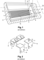
- Figure 1 is a schematic view of an underground chamber having a secondary closure in accordance with the state of the art.
- the underground chamber 1 is in the form of a rectangular shaft formed in the ground.
- the underground chamber has walls 2, here made of concrete.
- the upper edge of the underground chamber 1 is reinforced by a frame 3.
- the frame 3 is generally metallic and forms a bearing surface 4 on which a cover can be placed in order to close the underground chamber 1.
- a secondary closure of the chamber is provided, in the form of a grid 5.
- the grid 5, in the closed position, extends horizontally under the frame, and therefore under the cover (not shown) which forms a primary closure device for the underground chamber 1.
- the purpose of the grid 5 is to secure the underground chamber 1, essentially when opening the cover (or other primary closure device), or when said cover is opened or removed. Indeed, when opening the chamber cover, which is generally heavy, there is a risk that this cover or a tool may fall into the underground chamber 1. There is also a risk of falling into the underground chamber for the operator who opens the cover.
- the secondary closing device thus prevents the cover, a tool, or a person from falling to the bottom of the underground chamber 1. This avoids a risk of injury to the person concerned, and/or damage to the equipment contained in the underground chamber 1.
- Grid 5 which is not subjected to such significant and repeated forces (for example the passage of vehicles) as the primary closure, must nevertheless be securely fixed to underground chamber 1.
- supports 6 are, in the example shown here, securely fixed, preferably pegged, to opposite walls 2 of the underground chamber.
- the chamber is arbitrarily oriented by considering that the walls where the supports 6 are fixed are longitudinally opposed, that is to say here in a longitudinal direction L.
- the longitudinal direction corresponds in the example shown to the largest side of the underground chamber, which is rectangular in this example.
- the transverse direction T is defined as the horizontal direction perpendicular to the longitudinal direction L, and here it is parallel to the short side of the rectangular chamber.
- the supports 6 thus comprise: a first support 7, allowing the extraction or articulation of the grid 5 (to bring it into the open position), and a second support 8.
- the first support 7 is in the form of two solid and rigid brackets. Each bracket has a first portion 9 which has holes 10 each allowing the installation of an anchor pin. A second portion 11 of the bracket has a hook 12 which is attached, for example welded, to the first support.
- the hook 12 makes it possible to block a transverse axis 13 of the grid 5 in order to allow it to tilt.
- the second support 8 also comprises two solid and rigid brackets.
- a first portion 9 of each bracket comprises orifices 10 each allowing the installation of an anchor pin.
- At least one of the two brackets of the second support 8 comprises a ring 14 fixed, for example welded, on its second portion 11.
- the ring 14 then protrudes above an upper surface 15 of the grid.
- a padlock can be placed in the ring 14, in order to lock the grid 5 in the closed position.
- a precision of the order of 2 mm is necessary to guarantee the correct positioning and correct operation of the grid 5.
- such precision is rarely achieved with certainty with regard to the spacing between the opposite walls of an underground chamber, which requires adapting the position of the supports during their assembly, for example by means of shims.
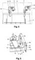
- FIG. 3 illustrates supports 6A in accordance with a first embodiment of the invention.
- the supports 6A comprise a first support 7A and a second support 8A.
- the first support 7A comprises two parts, namely two angles 16.
- the two angles 16 may be identical.
- Each angle 16 comprises a fixing wing 17 intended to be fixed, for example pegged, to a wall of the underground chamber.
- the fixing wing 17 may thus comprise orifices 10 each allowing the installation of an anchoring pin.
- the orifices 10 are oblong, allowing a certain adaptation of the transverse position of the angles 16.
- Each angle 16 also comprises a wing 18, perpendicular to the fixing wing 17.
- Wing 18 has a slot 19.
- the slot 19 has a substantially constant width l.
- This width l is such that it allows the passage, with a small clearance, of the axis 13 of the grid 5, which has a diameter D.
- the slot 19 can have a complex trajectory, for example essentially curvilinear. In the example shown here, the slot 19 has a substantially “C” shaped trajectory.
- the slot 19 has an end portion 20, which is closed and straight. This end portion is substantially horizontal when the first support 7A is fixed in an underground chamber.
- the two angles 16 are fixed so that their wings 18 are parallel to each other and aligned.
- the axis 13 of the grid 5 is introduced into the slot 19 of each of the angles 16 through its inlet 21 (start of the upper branch of the “C” formed by the slot).
- the axis 13 is then advanced in each slot 19 of the angles until the axis 13 is in the terminal portion 20 (formed by the lower branch of the “C”).
- the axis 13 can then no longer escape from the first support 7A from the top. It nevertheless remains free to rotate, and its longitudinal position can also be adapted, to a certain extent.
- the length of the terminal portion of the slot 19 can be of the order of 20 mm to 30 mm, allowing a corresponding adaptation of the longitudinal position of the axis 13.
- the axis 13 is positioned near the closed end of the terminal portion 20, which corresponds to the position of the axis 13 when the grid 5 is tilted towards its open position.
- the “C” configuration of the slot 19 allows the axis 13 to be spaced from the wall 2 of the chamber, which improves the stability in the open position of the grid 5.
- the grid 5 assuming that it is free at its opposite longitudinal end, can be very easily removed from the first support 7A, by making the axis 13 follow the path of the slot 19 to its entrance 21.
- Each of the two angles 16 forming the first support 7A can be obtained by cutting and folding (in a single 90° fold) a metal plate.
- a steel plate for example stainless or galvanized steel
- a thickness of approximately 3 mm can, for example: be used for this purpose.
- a scrap of metal plate can generally be used to form each angle 16.
- each angle 16A comprises a fixing wing 17A intended to be fixed, for example pegged, to a wall of the underground chamber (opposite the wall where the first support 7A is fixed).
- the fixing wing 17A of each angle may thus comprise orifices 10 each allowing the installation of an anchoring peg.
- the orifices 10 are oblong, allowing a certain adaptation of the transverse position of the angles 16A.
- Each angle iron 16A forms a tab 22, which extends perpendicular to the fixing wing 17A.
- the tab 22 further extends vertically, so that it passes through a notch 23 formed in the grid 5 when the latter is placed in abutment on the second support 8A, as shown in Figure 6 .
- the notch 23 preferably has an elongated shape, in the longitudinal direction.
- the length w of the notch 23 is advantageously greater than the width e of the tab 22.
- At least one of the legs 22 of the second support 8A has a hole 24.
- the hole 24 is located above the grid 5, more precisely above the upper surface 15 of the grid 5.
- Hole 24 allows a padlock or any other suitable locking device to be passed through it, in order to lock the grid 5 in its closed position.
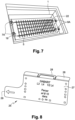
- FIG. 7 is a three-dimensional schematic view of an underground chamber 1 comprising a secondary closure device comprising the supports of the Figure 3 .
- underground chamber 1 of the Figure 7 differs from it by the secondary closing device used.
- the first support 7A comprising the two angles 16 having a slot 19 into which the axis 13 of the grid 5 is introduced, is fixed to a first wall of a longitudinal end of the underground chamber 1.
- the second support 8A comprising two angles 16A comprising tabs 22 allowing the locking of the grid 5 is fixed on the wall of the underground chamber 1 opposite longitudinally.
- FIG 8 represents a template allowing correct positioning of the angles forming respectively the first support 7A and the second support 8A in an underground chamber.
- This template 25 is formed from a plate so that it comprises a first surface 26 and a second perpendicular surface 27.
- the first surface 26 of the template 25 is intended to be placed in contact with an upper edge of the underground chamber 1, in this case on the support surface 4 of the frame 3 of the chamber.
- the first surface 27 may comprise a handle 28 which is foldable in order to facilitate the handling of the template 25.
- the second surface 27 is pressed into contact with the wall 2 of the underground chamber 1 on which one of the first support 7A or second support 8A is to be fixed.
- An edge 29 of the template 25 is placed in contact with the wall of the chamber which is perpendicular to the wall of the chamber to which the first support 7A or the second support 8A is to be fixed.
- the second surface 27 of the template comprises openings 30 whose position corresponds to the position of the holes to be made.
- openings 30 having various shapes may be present in the second surface 27.
- the openings have the correct spacing between them in the transverse direction for mounting a suitable grid 5, and, two openings 30 of the same shape have the correct vertical spacing, corresponding to the vertical spacing of the orifices 10 of the supports.
- the selection of the openings used to make the holes in the wall 2 of the underground chamber 1 makes it possible to choose the installation depth of the grid 5 with respect to the support surface 4 of the frame 3.
- FIG. 10 represents an example of a support for the secondary closure of an underground chamber, in this case the first support 7B, according to an embodiment of the prior art in which the supports are linked to one side of the frame of the underground chamber.
- Figure 10 illustrates the fact that the support of a secondary closure device can be connected directly to the frame 3. This simplifies the installation of the secondary closure, but, of course, this is only possible for underground chambers which must be equipped with such a secondary closure from the outset.
- the first support 7B comprises two tabs 31 welded to the frame 3. Each tab 31 comprises a perforated plate 32 allowing an axis 33 to be mounted there (for example in the form of a bolt) for the articulation of a grid 5.
- the second corresponding support 8B also includes two tabs 31A each forming a support to receive the grid 5. At least one of the two tabs 31 can be equipped with a ring 14A for locking the grid 5, for example using a padlock.
- the support of the figures 10 And 11 is complex, requires many welded parts, and does not allow tool-free disassembly of the grid from the frame 3.
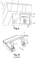
- supports 6C comprising a first support 7C shown in Figure 12 and a second 8C support shown in the Figure 13 .
- the first support 7C is formed from a part comprising a central plate 34 and two wings 18A parallel to each other and perpendicular to the central plate 34.
- the central plate 34 further comprises an end portion 35 which is welded to the frame 3.
- Each wing 18A has a slot 19A.
- Slot 19A just like the slot of the embodiment of the figures 3 to 7 , has a substantially constant width such that it allows the passage, with little play, of the axis 13 of the grid 5.
- the slot 19A has, in the example shown here, a substantially “S” shaped trajectory.
- the slot 19A has an end portion 20A, which is closed, straight and substantially horizontal when the frame 3 is in place on an underground chamber.
- the axis 13 of the grid can easily be inserted into the slot 19A and placed in the portion 20A, from where it can then no longer escape from the first support 7C from above.
- the grid 5 can nevertheless be tilted, around its axis 13, to an open position. The removal of the grid from the first support 7C can be carried out without tools.
- the second 8C support shown in the Figure 13 , has a general constitution similar to that of the first support 7C.
- the second support 8C comprises a central plate 34A having an end portion 35A which is welded to the frame 3.
- the second support further comprises two legs 22A, which extend perpendicular to the central plate 34A.
- the legs 22A also extend vertically, so that they pass through the notches 23 formed in the grid 5 when the latter is placed in abutment on the second support 8C.
- the legs 22A advantageously have a width less than the length of the notches 23.
- At least one of the legs 22A comprises a hole 24 located above the grid 5, more precisely above the upper surface 15 of the grid 5 when the latter is resting on the second support 8C.
- Hole 24 allows a padlock or any other suitable locking device to be passed through it, in order to lock the grid 5 in its closed position.
- the first support 7C and the second support 8C can be made by folding and cutting a metal sheet, without any additional parts. They also allow the installation and removal of the grid very easily and without tools.
- the frames comprising the support for the secondary closing grid according to the figures 12 And 13 are stackable for storage and transport, without requiring any part (wooden block or other) interposed between the frames. This is not the case for frames known in the prior art such as that of Figures 11 and 12 , because elements of the first support 7B and/or of the second support 8B (in particular the perforated plates 32 or the rings 14A) would interfere.
- FIG 14 shows a frame 3 having a secondary closing support.
- the support of the figure 14 may correspond to the one illustrated in figures 12 And 13 .
- the longitudinal direction L corresponds, on the figure 14 , to the direction of the smallest side of frame 3.
- the transverse direction T is that of the largest side of frame 3.
- FIG. 15 illustrates a grid 5 which can thus be used to form a secondary closure device in accordance with an embodiment of the invention.
- the grid 5 has the particularity of comprising on either side (in the longitudinal direction L) structures which each form a portion of axis 13 and a notch 23.
- the grid is thus symmetrical and can be mounted indifferently in one direction or the other.
- the axis 13 is here formed of several coaxial portions.
- a secondary closing device for an underground chamber allowing easy installation and removal of a grid, and tolerating significant dispersions in the dimensions of the underground chamber or the frame, for example up to 20 mm to 30 mm.
- the support for the secondary closing grid can also be obtained by simple bending and cutting of metal plates, and is therefore simple and inexpensive to obtain.
Landscapes
- Engineering & Computer Science (AREA)
- Environmental & Geological Engineering (AREA)
- Life Sciences & Earth Sciences (AREA)
- General Life Sciences & Earth Sciences (AREA)
- Mining & Mineral Resources (AREA)
- Paleontology (AREA)
- Civil Engineering (AREA)
- General Engineering & Computer Science (AREA)
- Structural Engineering (AREA)
- Underground Structures, Protecting, Testing And Restoring Foundations (AREA)
- Wing Frames And Configurations (AREA)
- Bulkheads Adapted To Foundation Construction (AREA)
Applications Claiming Priority (1)
| Application Number | Priority Date | Filing Date | Title |
|---|---|---|---|
| FR2312468A FR3155248B1 (fr) | 2023-11-14 | 2023-11-14 | Dispositif de fermeture secondaire d’une chambre souterraine |
Publications (2)
| Publication Number | Publication Date |
|---|---|
| EP4556635A1 true EP4556635A1 (de) | 2025-05-21 |
| EP4556635B1 EP4556635B1 (de) | 2026-05-13 |
Family
ID=90123471
Family Applications (1)
| Application Number | Title | Priority Date | Filing Date |
|---|---|---|---|
| EP24212580.5A Active EP4556635B1 (de) | 2023-11-14 | 2024-11-13 | Vorrichtung zum sekundärschliessen einer unterirdischen kammer |
Country Status (2)
| Country | Link |
|---|---|
| EP (1) | EP4556635B1 (de) |
| FR (1) | FR3155248B1 (de) |
Citations (5)
| Publication number | Priority date | Publication date | Assignee | Title |
|---|---|---|---|---|
| US5941024A (en) * | 1998-03-20 | 1999-08-24 | Journault-Jourplex Inc. | Floor hatch with integrated security fence |
| FR2792662A1 (fr) | 1999-04-23 | 2000-10-27 | Fond De Brousseval Et Montreui | Dispositif d'obstruction secondaire pour chambre d'acces a un ouvrage souterrain |
| WO2012123672A2 (fr) * | 2011-03-17 | 2012-09-20 | Norinco | Ensemble à cadre de support et grille de sécurité antichute réversible pouvant être montée articulée à l'un ou l'autre des deux côtés opposés du cadre |
| EP2933382A1 (de) * | 2014-04-18 | 2015-10-21 | EJ Emea | Strassenbaueinrichtung mit rahmen, an den angepasste laschen für die befestigung und auflagerung eines absturzsicherungsgitters angebracht sind |
| FR3062860A1 (fr) | 2017-02-13 | 2018-08-17 | Fonderies De Brousseval & Montreuil | Grille anti-chutes a support de boitier d'epissurage integre |
-
2023
- 2023-11-14 FR FR2312468A patent/FR3155248B1/fr active Active
-
2024
- 2024-11-13 EP EP24212580.5A patent/EP4556635B1/de active Active
Patent Citations (5)
| Publication number | Priority date | Publication date | Assignee | Title |
|---|---|---|---|---|
| US5941024A (en) * | 1998-03-20 | 1999-08-24 | Journault-Jourplex Inc. | Floor hatch with integrated security fence |
| FR2792662A1 (fr) | 1999-04-23 | 2000-10-27 | Fond De Brousseval Et Montreui | Dispositif d'obstruction secondaire pour chambre d'acces a un ouvrage souterrain |
| WO2012123672A2 (fr) * | 2011-03-17 | 2012-09-20 | Norinco | Ensemble à cadre de support et grille de sécurité antichute réversible pouvant être montée articulée à l'un ou l'autre des deux côtés opposés du cadre |
| EP2933382A1 (de) * | 2014-04-18 | 2015-10-21 | EJ Emea | Strassenbaueinrichtung mit rahmen, an den angepasste laschen für die befestigung und auflagerung eines absturzsicherungsgitters angebracht sind |
| FR3062860A1 (fr) | 2017-02-13 | 2018-08-17 | Fonderies De Brousseval & Montreuil | Grille anti-chutes a support de boitier d'epissurage integre |
Also Published As
| Publication number | Publication date |
|---|---|
| FR3155248B1 (fr) | 2025-11-28 |
| FR3155248A1 (fr) | 2025-05-16 |
| EP4556635B1 (de) | 2026-05-13 |
Similar Documents
| Publication | Publication Date | Title |
|---|---|---|
| EP1525354B1 (de) | Gitter zum verschliessen einer rinne oder ähnlichem | |
| FR2519665A1 (fr) | Regard circulaire de chaussee a demi-tampons articules | |
| EP2511421A1 (de) | Moduläre Sicherheitsabsperrbarriere mit Schnellmontagesystem | |
| CA2577042A1 (fr) | Dispositif permettant d'obturer un cadre, comprenant un panneau monte articule amovible sur le cadre | |
| EP4556635B1 (de) | Vorrichtung zum sekundärschliessen einer unterirdischen kammer | |
| EP2650460A2 (de) | Vorrichtung zum provisorischen Verschließen eines Öffnungselements auf einem Rahmenelement | |
| EP3230532B1 (de) | Anordnung für eine strassenschacht mit einem rahmen, deckel und kit zur gelenkigen montage des deckels am rahmen | |
| FR2799478A1 (fr) | Dispositif de fermeture de regard de visite ou d'inspection | |
| EP2832949A1 (de) | Steuerungssystem für die Lamellen von Jalousien, und entsprechende Jalousie | |
| WO2010108808A1 (fr) | Dispositif antivol pour colonne de direction et procedes associes de montage d'un etrier de maintien | |
| FR3109958A1 (fr) | Portillon notamment pour une porte de garage et porte de garage equipee dudit portillon | |
| FR2933723A1 (fr) | Dispositif de coffrage | |
| FR2495884A1 (fr) | Dispositif de reception d'au moins une plaquette, notamment de circuit imprime, et utilisation d'un tel dispositif | |
| EP2933382B1 (de) | Strassenbaueinrichtung mit rahmen, an den angepasste laschen für die befestigung und auflagerung eines absturzsicherungsgitters angebracht sind | |
| EP4074932B1 (de) | Stromverteilerkasten und verfahren zur herstellung eines solchen stromverteilerkastens | |
| FR2792662A1 (fr) | Dispositif d'obstruction secondaire pour chambre d'acces a un ouvrage souterrain | |
| EP1215342B1 (de) | Verriegelungseinheit für eine Platte zum Verschliessen eines Zugangs zu einer unterirdischen Kammer | |
| FR3021732A1 (fr) | Systeme de trappe pour conduit d'evacuation de fumee ou similaire | |
| FR2683569A1 (fr) | Procede et dispositif d'assemblage de poutres en bois. | |
| WO2025224028A1 (fr) | Dispositif de couverture pour caniveau | |
| FR3142209A3 (fr) | Verrou fixé au profil d’extrémité d’un élément de clôture pivotant avec charnières | |
| EP1191153A1 (de) | Schachtabdeckung mit Scharnier | |
| FR3016381A1 (fr) | Bras lateraux pour banche de coffrage. | |
| WO2023089270A1 (fr) | Dispositif d'accès à une infrastructure souterraine comportant une jambe de maintien en position entrouverte | |
| FR2851777A1 (fr) | Dispositif d'acces et de fermeture securisee des chambres enterrees et procedes de mise en oeuvre |
Legal Events
| Date | Code | Title | Description |
|---|---|---|---|
| PUAI | Public reference made under article 153(3) epc to a published international application that has entered the european phase |
Free format text: ORIGINAL CODE: 0009012 |
|
| STAA | Information on the status of an ep patent application or granted ep patent |
Free format text: STATUS: THE APPLICATION HAS BEEN PUBLISHED |
|
| AK | Designated contracting states |
Kind code of ref document: A1 Designated state(s): AL AT BE BG CH CY CZ DE DK EE ES FI FR GB GR HR HU IE IS IT LI LT LU LV MC ME MK MT NL NO PL PT RO RS SE SI SK SM TR |
|
| STAA | Information on the status of an ep patent application or granted ep patent |
Free format text: STATUS: REQUEST FOR EXAMINATION WAS MADE |
|
| 17P | Request for examination filed |
Effective date: 20251110 |
|
| GRAP | Despatch of communication of intention to grant a patent |
Free format text: ORIGINAL CODE: EPIDOSNIGR1 |
|
| STAA | Information on the status of an ep patent application or granted ep patent |
Free format text: STATUS: GRANT OF PATENT IS INTENDED |
|
| RIC1 | Information provided on ipc code assigned before grant |
Ipc: E02D 29/12 20060101AFI20260224BHEP Ipc: E02D 29/14 20060101ALI20260224BHEP |
|
| GRAS | Grant fee paid |
Free format text: ORIGINAL CODE: EPIDOSNIGR3 |
|
| GRAA | (expected) grant |
Free format text: ORIGINAL CODE: 0009210 |
|
| STAA | Information on the status of an ep patent application or granted ep patent |
Free format text: STATUS: THE PATENT HAS BEEN GRANTED |
|
| INTG | Intention to grant announced |
Effective date: 20260311 |
|
| RIN1 | Information on inventor provided before grant (corrected) |
Inventor name: CARBON, LUDOVIC Inventor name: DEDUIT, BENOIT |
|
| AK | Designated contracting states |
Kind code of ref document: B1 Designated state(s): AL AT BE BG CH CY CZ DE DK EE ES FI FR GB GR HR HU IE IS IT LI LT LU LV MC ME MK MT NL NO PL PT RO RS SE SI SK SM TR |
|
| REG | Reference to a national code |
Ref country code: CH Ref legal event code: F10 Free format text: ST27 STATUS EVENT CODE: U-0-0-F10-F00 (AS PROVIDED BY THE NATIONAL OFFICE) Effective date: 20260513 |