EP4556675A1 - Abdeckplattengruppe für einen wicklersitz eines wicklerkastens mit einer öffnung für einen schalter und zugehörige abdeckplatte mit öffnung für einen schalter - Google Patents
Abdeckplattengruppe für einen wicklersitz eines wicklerkastens mit einer öffnung für einen schalter und zugehörige abdeckplatte mit öffnung für einen schalter Download PDFInfo
- Publication number
- EP4556675A1 EP4556675A1 EP24212751.2A EP24212751A EP4556675A1 EP 4556675 A1 EP4556675 A1 EP 4556675A1 EP 24212751 A EP24212751 A EP 24212751A EP 4556675 A1 EP4556675 A1 EP 4556675A1
- Authority
- EP
- European Patent Office
- Prior art keywords
- plate
- cover plate
- sub
- opening
- switch
- Prior art date
- Legal status (The legal status is an assumption and is not a legal conclusion. Google has not performed a legal analysis and makes no representation as to the accuracy of the status listed.)
- Withdrawn
Links
Images



Classifications
-
- E—FIXED CONSTRUCTIONS
- E06—DOORS, WINDOWS, SHUTTERS, OR ROLLER BLINDS IN GENERAL; LADDERS
- E06B—FIXED OR MOVABLE CLOSURES FOR OPENINGS IN BUILDINGS, VEHICLES, FENCES OR LIKE ENCLOSURES IN GENERAL, e.g. DOORS, WINDOWS, BLINDS, GATES
- E06B9/00—Screening or protective devices for wall or similar openings, with or without operating or securing mechanisms; Closures of similar construction
- E06B9/56—Operating, guiding or securing devices or arrangements for roll-type closures; Spring drums; Tape drums; Counterweighting arrangements therefor
- E06B9/78—Operating, guiding or securing devices or arrangements for roll-type closures; Spring drums; Tape drums; Counterweighting arrangements therefor for direct manual operation, e.g. by tassels, by handles
-
- E—FIXED CONSTRUCTIONS
- E06—DOORS, WINDOWS, SHUTTERS, OR ROLLER BLINDS IN GENERAL; LADDERS
- E06B—FIXED OR MOVABLE CLOSURES FOR OPENINGS IN BUILDINGS, VEHICLES, FENCES OR LIKE ENCLOSURES IN GENERAL, e.g. DOORS, WINDOWS, BLINDS, GATES
- E06B9/00—Screening or protective devices for wall or similar openings, with or without operating or securing mechanisms; Closures of similar construction
- E06B9/56—Operating, guiding or securing devices or arrangements for roll-type closures; Spring drums; Tape drums; Counterweighting arrangements therefor
- E06B9/68—Operating devices or mechanisms, e.g. with electric drive
- E06B9/74—Operating devices or mechanisms, e.g. with electric drive adapted for selective electrical or manual operation
-
- E—FIXED CONSTRUCTIONS
- E06—DOORS, WINDOWS, SHUTTERS, OR ROLLER BLINDS IN GENERAL; LADDERS
- E06B—FIXED OR MOVABLE CLOSURES FOR OPENINGS IN BUILDINGS, VEHICLES, FENCES OR LIKE ENCLOSURES IN GENERAL, e.g. DOORS, WINDOWS, BLINDS, GATES
- E06B9/00—Screening or protective devices for wall or similar openings, with or without operating or securing mechanisms; Closures of similar construction
- E06B9/56—Operating, guiding or securing devices or arrangements for roll-type closures; Spring drums; Tape drums; Counterweighting arrangements therefor
- E06B9/78—Operating, guiding or securing devices or arrangements for roll-type closures; Spring drums; Tape drums; Counterweighting arrangements therefor for direct manual operation, e.g. by tassels, by handles
- E06B2009/785—Operating, guiding or securing devices or arrangements for roll-type closures; Spring drums; Tape drums; Counterweighting arrangements therefor for direct manual operation, e.g. by tassels, by handles by belts, straps, bands, tapes, cords, tassels
Definitions
- the present invention relates to a cover plate group for a winder seat of a winder box, in which a winder of a shutter suitable for closing a window or glass door compartment is generally placed. Furthermore, the present invention also relates to a cover plate.
- the present patent application relates to the field of shutter winders and, more specifically, to a cover plate for a winder box, designed to improve the aesthetics and functionality of existing winder boxes, especially in cases of non-use or replacement with motorized winders.
- an object of the present invention is to provide a cover plate group that is easy to install, compatible with standard winder boxes and capable of aesthetically adapting to various residential contexts whilst maintaining a discrete or elegant profile.
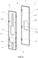
- a cover plate group 1 for a winder seat 21 of a winder box 2 for a winder of a shutter of a window or glass door compartment is collectively indicated with the reference numeral 1.
- the cover plate group 1 comprises a sub-plate 10, suitable for being fastened to the winder seat 21 and comprising one or more sub-plate coupling portions 11, 12, 13.
- the cover plate group 1 also comprises a cover plate 3 comprising a sub-plate seat 33 suitable for accommodating the sub-plate 10 therein when the cover plate 3 is coupled to the sub-plate 10.
- the cover plate 3 comprises a through opening 300 suitable for accommodating a switch 4 for the electrical control of a shutter motor.
- the cover plate 3 comprises one or more switch fastening holes 301, 302 suitable for fastening the switch 4 onto the cover plate 3 through a fastening device, such as one or more screws.
- the sub-plate 10 also comprises a sub-plate through opening 100 suitable for accommodating the switch 4.
- the sub-plate through opening 100 is aligned with the through opening 300 of the cover plate 3.
- the sub-plate through opening 100 is shaped identically to the through opening 300 of the cover plate 3.
- the through opening 300 is positioned to be centered with respect to the total length of the cover plate 3 along a major plate extension direction X' of the cover plate 3.
- the cover plate 3 comprises only the one or more switch fastening holes 301, 302 together with the through opening 300 and is therefore devoid of any other opening or hole for fastening the cover plate 3 to the sub-plate 10. This allows a simple and linear plate without unsightly holes or visible screws to be obtained, as well as ensures a simple installation.
- the one or more switch fastening holes 301, 302 are positioned in proximity to the through opening 300.
- the switch 4 is inserted into the through opening 300 and is fastened to the cover plate 3 through pins or screws passing through the one or more switch fastening holes 301, 302.
- the switch is self-contained, i.e. fully supported, preferably exclusively supported, directly by the cover plate 3.
- the sub-plate 10 comprises at least one auxiliary fastening hole 101 positioned so as to be aligned with one of said one or more switch fastening holes 301, 302 of the cover plate 3, when the cover plate 3 is coupled to the sub-plate 10.
- the switch is supported entirely by the cover plate 3 and also by means of the sub-plate 10, which strengthens the fastening thereof.
- the cover plate 3 comprises plate coupling portions 30, 31, 32 suitable for being snap-coupled to the one or more respective sub-plate coupling portions 11, 12, 13 for releasably snap-coupling the cover plate to the sub-plate 10. In this way, the winder seat 21 is simply and completely closed.
- the one or more sub-plate coupling portions 11, 12, 13 are a depression formed on a side 15 of the sides of the sub-plate 10.
- the plate coupling portions 30, 31, 32 are one or more teeth protruding from a plate side 35 of the peripheral sides 35, 36, 37, 38 of the cover plate 30.
- the one or more protruding teeth project toward the inside of the sub-plate seat 33.
- the one or more sub-plate coupling portions 11, 12, 13 are a tooth protruding from a side 15 of the sub-plate and wherein the plate coupling portions 30, 31, 32 are one or more depressions formed on a plate side 35 of the peripheral sides 35, 36, 37, 38 of the cover plate 30.
- the one or more depressions are on the side of the sub-plate seat 33.
- the sub-plate 10 comprises an upper fastening slot 16 and/or a lower fastening slot 17.
- the upper fastening slot 16 and the lower fastening slot 17 are each suitable for being crossed by a pin or a screw for stably fastening the sub-plate 10 to the winder box 2.
- the sub-plate 10 also comprises a belt opening 18 arranged between the upper fastening slot 16 and the lower fastening slot 17 along a major extension direction X of the sub-plate.
- the belt opening 18 is a through opening, open towards a single side 15 of the sub-plate 10 through a slit 151 which interrupts the continuity of said side 15. This may allow the belt of the manual shutter to be restored, once the cover plate has been removed, where necessary.
- the sub-plate 10 is completely made of a thermoplastic polymer.
- the sub-plate 10 is completely made of a metal, such as aluminum, sheet metal, or steel.
- the cover plate 3 is completely made of a thermoplastic polymer or a metal, for example aluminum, sheet metal or steel.
- the cover plate 3 has a rectangular plate shape having a completely flat front face 39 folded on the edges with rounded corners to form small peripheral plate sides 35, 36, 37, 38.
- the sub-plate 10 has a rectangular plate shape having a flat front face 19 folded on the edges with rounded corners to form plate sides 15, 15', 15'', 15''', suitable for abutting with the small peripheral plate sides 35, 36, 37, 38 on the side of the sub-plate seat 33, and preferably to be fully accommodated in such a sub-plate seat, so that the cover plate 3 entirely covers the sub-plate.
- an object of the present invention is also a cover plate 3 that may be coupled per se to a sub-plate 10 of a cover plate group 1 as described within any of the previously described embodiments, and in particular having a flat front face 39 folded on the edges with rounded corners to form small peripheral plate sides 35, 36, 37, 38 of the plate and being totally devoid of through openings. Obtained on said flat front face 39 is the through opening 300 suitable for accommodating the switch 4 for the electrical control of a motor of a shutter, and one or more switch fastening holes 301, 302 suitable for fastening the switch 4 onto the cover plate 3 through a fastening device, such as one or more screws.
- the cover plate 3 is devoid of any other opening or hole for fastening the cover plate 3 to the sub-plate 10 and/or to a winder box 2.
- the present invention brilliantly overcomes the drawbacks of the prior art and meets the needs of the industry.
- the proposed solution is easy to install and remove, is compatible with standard winder boxes and is capable of aesthetically adapting to various residential contexts, whilst maintaining a discrete profile.
- the cover plate group allows the box seat to be recovered by installing the switch in said seat by means of the cover plate group, in the case of retrofitting a manual winder with a motorized winder.
- the switch is placed into the box seat and the winder box may be used for the electrical connections without requiring excessive masonry works for the installation of the control switch.
- the possibility of snap-removing the plate allows the aesthetics of the plate to be adapted and re-adapted quickly to the residential context, without having to carry out screwing operations.
- the fact that the switch is supported directly by the cover plate ensures further ease of installation and fastening of the electrical connections to the switch, since it is not necessary to remove the sub-plate.
- the present invention allows manual winders to be retrofitted without having to cover the winder seat box with masonry works, instead using it exactly for that purpose.
- the cover plate has no further openings, but only the fastening holes of the switch, allows for a simple and linear plate to be obtained, especially since the switch plate also covers the fastening screws of the switch, making the whole assembled group 200 cover plate 3 and switch 4 completely devoid of visible screws.
Landscapes
- Engineering & Computer Science (AREA)
- Structural Engineering (AREA)
- Architecture (AREA)
- Civil Engineering (AREA)
- Operating, Guiding And Securing Of Roll- Type Closing Members (AREA)
Applications Claiming Priority (1)
| Application Number | Priority Date | Filing Date | Title |
|---|---|---|---|
| IT202300024102 | 2023-11-14 |
Publications (1)
| Publication Number | Publication Date |
|---|---|
| EP4556675A1 true EP4556675A1 (de) | 2025-05-21 |
Family
ID=89844980
Family Applications (1)
| Application Number | Title | Priority Date | Filing Date |
|---|---|---|---|
| EP24212751.2A Withdrawn EP4556675A1 (de) | 2023-11-14 | 2024-11-13 | Abdeckplattengruppe für einen wicklersitz eines wicklerkastens mit einer öffnung für einen schalter und zugehörige abdeckplatte mit öffnung für einen schalter |
Country Status (1)
| Country | Link |
|---|---|
| EP (1) | EP4556675A1 (de) |
Citations (3)
| Publication number | Priority date | Publication date | Assignee | Title |
|---|---|---|---|---|
| ES2396878A1 (es) * | 2009-12-18 | 2013-03-01 | Gaviota Simbac, S.L. | Sistema de sujeción de una placa embellecedora para un recogedor de persiana y placa embellecedora |
| EP2520754B1 (de) * | 2011-05-04 | 2015-12-09 | Alfred Schellenberg GmbH | Antrieb für einen Rolladengurt mit mehrstufigem Getriebe |
| EP2396489B1 (de) * | 2009-02-10 | 2018-04-04 | Stafer S.P.A. | Wickelvorrichtung für gurte und zugehörige abdeckung |
-
2024
- 2024-11-13 EP EP24212751.2A patent/EP4556675A1/de not_active Withdrawn
Patent Citations (3)
| Publication number | Priority date | Publication date | Assignee | Title |
|---|---|---|---|---|
| EP2396489B1 (de) * | 2009-02-10 | 2018-04-04 | Stafer S.P.A. | Wickelvorrichtung für gurte und zugehörige abdeckung |
| ES2396878A1 (es) * | 2009-12-18 | 2013-03-01 | Gaviota Simbac, S.L. | Sistema de sujeción de una placa embellecedora para un recogedor de persiana y placa embellecedora |
| EP2520754B1 (de) * | 2011-05-04 | 2015-12-09 | Alfred Schellenberg GmbH | Antrieb für einen Rolladengurt mit mehrstufigem Getriebe |
Similar Documents
| Publication | Publication Date | Title |
|---|---|---|
| US20130319624A1 (en) | Modular bracket system for window treatment | |
| US11732524B2 (en) | Mounting hardware assembly | |
| EP1719227B1 (de) | Einrichtung zur unterstützung einer bündigen wandanbringung für elektrische oder elektronische komponenten | |
| US4927039A (en) | Electrical box | |
| USRE41661E1 (en) | Electrical box assembly | |
| AU2012261549B2 (en) | Air Distribution Apparatus | |
| EP0849851B1 (de) | Kabelrohrendkappe | |
| EP1925889A2 (de) | Luftverteilungsanordnung | |
| US20150225995A1 (en) | Molded plastic access door | |
| US6625941B2 (en) | Detachable lineal for doors and windows | |
| US7757875B2 (en) | Pull out extension contained in electrical box | |
| US20200399952A1 (en) | Assembly of a Box, in Particular a Roller Shutter Box, and Mounting Frame | |
| US7358440B1 (en) | Rain shielded box for exiting through siding | |
| US20240204500A1 (en) | Flush-to-wall electrical box | |
| EP4556676A1 (de) | Abdeckplattenanordnung für einen wicklersitz eines wicklerkastens einer blende für ein fenster- oder glastürfach und zugehörige platte | |
| US4667483A (en) | Air conditioner | |
| US5746654A (en) | Ventilator | |
| GB2522058A (en) | Mounting apparatus for an electrical device | |
| US7402748B1 (en) | Reversible electrical box for residential and commercial ceiling construction | |
| EP3385492B1 (de) | Schnurhalterung | |
| JP2525211Y2 (ja) | 換気装置の化粧グリル | |
| CA3103399C (en) | Roller blind assembly and method of installing roller blinds | |
| AU2010212249B2 (en) | Door closer housing | |
| JP7539275B2 (ja) | 排水弁装置及びサッシ窓 | |
| EP2474681B1 (de) | Blendenvorrichtung und verfahren zur installation des gehäuses einer derartigen blendenvorrichtung |
Legal Events
| Date | Code | Title | Description |
|---|---|---|---|
| PUAI | Public reference made under article 153(3) epc to a published international application that has entered the european phase |
Free format text: ORIGINAL CODE: 0009012 |
|
| STAA | Information on the status of an ep patent application or granted ep patent |
Free format text: STATUS: THE APPLICATION HAS BEEN PUBLISHED |
|
| AK | Designated contracting states |
Kind code of ref document: A1 Designated state(s): AL AT BE BG CH CY CZ DE DK EE ES FI FR GB GR HR HU IE IS IT LI LT LU LV MC ME MK MT NL NO PL PT RO RS SE SI SK SM TR |
|
| STAA | Information on the status of an ep patent application or granted ep patent |
Free format text: STATUS: THE APPLICATION IS DEEMED TO BE WITHDRAWN |
|
| 18D | Application deemed to be withdrawn |
Effective date: 20251122 |