EP4556682A1 - Ensemble de refroidissement par impact pour un carter de moteur rotatif d'aéronef - Google Patents
Ensemble de refroidissement par impact pour un carter de moteur rotatif d'aéronef Download PDFInfo
- Publication number
- EP4556682A1 EP4556682A1 EP24213682.8A EP24213682A EP4556682A1 EP 4556682 A1 EP4556682 A1 EP 4556682A1 EP 24213682 A EP24213682 A EP 24213682A EP 4556682 A1 EP4556682 A1 EP 4556682A1
- Authority
- EP
- European Patent Office
- Prior art keywords
- baffle plate
- impingement cooling
- housing body
- outlet
- coolant
- Prior art date
- Legal status (The legal status is an assumption and is not a legal conclusion. Google has not performed a legal analysis and makes no representation as to the accuracy of the status listed.)
- Pending
Links
Images




Classifications
-
- F—MECHANICAL ENGINEERING; LIGHTING; HEATING; WEAPONS; BLASTING
- F01—MACHINES OR ENGINES IN GENERAL; ENGINE PLANTS IN GENERAL; STEAM ENGINES
- F01C—ROTARY-PISTON OR OSCILLATING-PISTON MACHINES OR ENGINES
- F01C21/00—Component parts, details or accessories not provided for in groups F01C1/00 - F01C20/00
- F01C21/06—Heating; Cooling; Heat insulation
-
- F—MECHANICAL ENGINEERING; LIGHTING; HEATING; WEAPONS; BLASTING
- F01—MACHINES OR ENGINES IN GENERAL; ENGINE PLANTS IN GENERAL; STEAM ENGINES
- F01C—ROTARY-PISTON OR OSCILLATING-PISTON MACHINES OR ENGINES
- F01C1/00—Rotary-piston machines or engines
- F01C1/22—Rotary-piston machines or engines of internal-axis type with equidirectional movement of co-operating members at the points of engagement, or with one of the co-operating members being stationary, the inner member having more teeth or tooth- equivalents than the outer member
-
- F—MECHANICAL ENGINEERING; LIGHTING; HEATING; WEAPONS; BLASTING
- F01—MACHINES OR ENGINES IN GENERAL; ENGINE PLANTS IN GENERAL; STEAM ENGINES
- F01C—ROTARY-PISTON OR OSCILLATING-PISTON MACHINES OR ENGINES
- F01C21/00—Component parts, details or accessories not provided for in groups F01C1/00 - F01C20/00
- F01C21/10—Outer members for co-operation with rotary pistons; Casings
- F01C21/104—Stators; Members defining the outer boundaries of the working chamber
- F01C21/108—Stators; Members defining the outer boundaries of the working chamber with an axial surface, e.g. side plates
-
- F—MECHANICAL ENGINEERING; LIGHTING; HEATING; WEAPONS; BLASTING
- F04—POSITIVE - DISPLACEMENT MACHINES FOR LIQUIDS; PUMPS FOR LIQUIDS OR ELASTIC FLUIDS
- F04C—ROTARY-PISTON, OR OSCILLATING-PISTON, POSITIVE-DISPLACEMENT MACHINES FOR LIQUIDS; ROTARY-PISTON, OR OSCILLATING-PISTON, POSITIVE-DISPLACEMENT PUMPS
- F04C2240/00—Components
- F04C2240/30—Casings or housings
-
- F—MECHANICAL ENGINEERING; LIGHTING; HEATING; WEAPONS; BLASTING
- F04—POSITIVE - DISPLACEMENT MACHINES FOR LIQUIDS; PUMPS FOR LIQUIDS OR ELASTIC FLUIDS
- F04C—ROTARY-PISTON, OR OSCILLATING-PISTON, POSITIVE-DISPLACEMENT MACHINES FOR LIQUIDS; ROTARY-PISTON, OR OSCILLATING-PISTON, POSITIVE-DISPLACEMENT PUMPS
- F04C2270/00—Control; Monitoring or safety arrangements
- F04C2270/19—Temperature
- F04C2270/195—Controlled or regulated
Definitions
- This disclosure relates generally to rotary engines for aircraft and, more particularly, to an impingement cooling assembly for a rotary engine housing.
- a rotary engine for an aircraft may be configured, for example, as a Wankel engine.
- the rotary engine includes one or more rotors configured to eccentrically rotate within an engine housing.
- the engine housing may be exposed to high temperatures during operation of the rotary engine.
- Various methods and engine housing configurations are known in the art for mitigating high-temperature conditions for rotary engines housings. While these known methods and engine housing configurations have various advantages, there is still room in the art for improvement.
- an engine housing for an aircraft rotary engine includes a rotor housing and a side housing assembly.
- the rotor housing includes a rotor housing body.
- the rotor housing body extends about an axis to form a rotor cavity of the engine housing.
- the rotor housing body extends between and to a first axial end and a second axial end.
- the side housing assembly includes a side housing body, a side plate, and an impingement cooling assembly.
- the side housing body is disposed at the first axial end.
- the side plate is disposed axially between the rotor housing body and the side housing body.
- the side plate includes an inner side, an outer side, and a perimeter edge extending from the inner side to the outer side.
- the inner side further forms the rotor cavity.
- the impingement cooling assembly includes a first baffle plate.
- the first baffle plate is disposed between the side housing body and the side plate.
- the side housing body, the side plate, and the first baffle plate form a coolant passage of the impingement cooling assembly.
- the coolant passage includes an inlet plenum and a plurality of impingement cooling holes.
- the first baffle plate forms the plurality of impingement cooling holes.
- Each impingement cooling hole of the plurality of impingement cooling holes includes a cooling hole inlet and a cooling hole outlet.
- the cooling hole inlet is disposed at the inlet plenum.
- Each impingement cooling hole of the plurality of impingement cooling holes is configured to direct a coolant from the inlet plenum toward and onto the outer side from the cooling hole outlet.
- the inlet plenum may be formed by the side housing body and the first baffle plate.
- the coolant passage may further include an outlet plenum.
- the outlet plenum may be formed by the first baffle plate and the side plate.
- the cooling hole outlet may be disposed at the outlet plenum.
- the impingement cooling assembly may further include a second baffle plate disposed between the side housing body and the side plate.
- the second baffle plate may be axially spaced from the first baffle plate.
- the coolant passage may further include an outlet plenum. The outlet plenum may be formed by one or both of the first baffle plate and the second baffle plate.
- the inlet plenum may be formed by and between the first baffle plate and the second baffle plate.
- the outlet plenum may be formed by and between the first baffle plate and the second baffle plate.
- the side housing body, the side plate, the first baffle plate, and the second baffle plate may form a plurality of coolant cells of the impingement cooling assembly.
- Each coolant cell of the plurality of coolant cells may include at least one impingement cooling hole of the plurality of impingement cooling holes, one or more coolant outlet holes, and an impingement cooling cavity.
- the at least one impingement cooling hole may extend between and connect the inlet plenum and the impingement cooling cavity.
- the one or more coolant outlet holes may extend between and connect the outlet plenum and the impingement cooling cavity.
- the impingement cooling cavity may be disposed at the outer side.
- the at least one impingement cooling hole may extend through one of the first baffle plate or the second baffle plate.
- the at least one impingement cooling hole may extend through the first baffle plate and the second baffle plate.
- the impingement cooling cavity sidewall may extend between and to the second baffle plate and the side plate.
- the impingement cooling cavity sidewall may circumscribe the impingement cooling cavity.
- the side housing body, the side plate, and the first baffle plate may form a unitary structure.
- the impingement cooling assembly may further include a second baffle plate disposed between the side housing body and the side plate.
- the second baffle plate further may form the unitary structure.
- the second baffle plate may be axially spaced from the first baffle plate.
- the coolant passage may further include an outlet plenum.
- the outlet plenum may be formed by one or both of the first baffle plate and the second baffle plate.
- an engine housing for an aircraft rotary engine includes a side housing assembly.
- the side housing assembly extends along an axis.
- the side housing assembly includes a side housing body, a side plate, and an impingement cooling assembly.
- the side housing body and the side plate extend about the axis.
- the side plate includes an inner axial side, an outer axial side, and a perimeter edge extending from the inner axial side to the outer axial side.
- the outer axial side is disposed at the side housing body.
- the impingement cooling assembly includes a baffle plate. The baffle plate, the side housing body, and the side plate form a coolant passage of the impingement cooling assembly axially between the side housing body and the outer axial side.
- the coolant passage extends about the axis.
- the coolant passage includes an inlet plenum and a plurality of impingement cooling holes.
- the baffle plate forms the plurality of impingement cooling holes.
- Each impingement cooling hole of the plurality of impingement cooling holes includes a cooling hole inlet and a cooling hole outlet.
- the cooling hole inlet is disposed at the inlet plenum.
- Each impingement cooling hole of the plurality of impingement cooling holes is configured to direct a coolant from the inlet plenum toward and onto the outer side from the cooling hole outlet.
- each impingement cooling hole of the plurality of impingement cooling holes extends axially from the cooling hole inlet to the cooling hole outlet to direct the coolant orthogonally toward and onto the outer side.
- the baffle plate forms a nozzle for each impingement cooling hole of the plurality of impingement cooling holes at the cooling hole outlet.
- the nozzle may extend toward the outer side relative to a surrounding portion of the baffle plate.
- an engine housing for an aircraft rotary engine includes a rotor housing and a side housing assembly.
- the rotor housing includes a rotor housing body.
- the rotor housing body extends about an axis to form a rotor cavity of the engine housing.
- the side housing assembly includes a side housing body, a side plate, and an impingement cooling assembly.
- the side housing body is disposed mounted to the rotor housing body.
- the side plate is disposed axially between the rotor housing body and the side housing body.
- the side plate includes an inner side and an outer side. The inner side further forms the rotor cavity.
- the impingement cooling assembly includes at least one baffle plate.
- the at least one baffle plate is disposed axially between the side housing body and the side plate.
- the side housing body, the side plate, and the at least one baffle plate form a coolant passage of the impingement cooling assembly.
- the coolant passage includes a plurality of impingement cooling holes, an inlet plenum upstream of the plurality of impingement cooling holes, and an outlet plenum downstream of the plurality of impingement cooling holes.
- the at least one baffle plate separates the inlet plenum from the outlet plenum.
- Each impingement cooling hole of the plurality of impingement cooling holes includes a cooling hole inlet and a cooling hole outlet.
- the cooling hole inlet is disposed at the inlet plenum.
- Each impingement cooling hole of the plurality of impingement cooling holes is configured to direct a coolant from the inlet plenum toward and onto the outer side from the cooling hole outlet.
- the side housing body, the side plate, and the at least one baffle plate may form a unitary structure.
- the at least one baffle plate may include a first baffle plate and a second baffle plate axially spaced from the first baffle plate.
- FIG. 1 illustrates an engine assembly 10.
- the engine assembly 10 may form a portion of a propulsion system for an aircraft.
- the aircraft may be a fixed-wing aircraft (e.g., an airplane), a rotary-wing aircraft (e.g., a helicopter), a tilt-rotor aircraft, a tilt-wing aircraft, or another aerial vehicle.
- the aircraft may be a manned aerial vehicle or an unmanned aerial vehicle (UAV, e.g., a drone).
- UAV unmanned aerial vehicle
- the engine assembly 10 may also form a portion of an auxiliary power unit (APU) or onboard generator for an aircraft.
- APU auxiliary power unit
- the engine assembly 10 of FIG. 1 includes an engine 12, a rotational load 14, a compressor section 16, a turbine section 18, and a rotational assembly 20.
- the engine 12 of FIG. 1 is configured as a rotary intermittent internal combustion engine, which intermittent internal combustion engine includes a rotor assembly 24 and an engine shaft 26.
- the rotor assembly 24 may be configured, for example, as a Wankel engine in which an eccentric rotor configuration is used to convert fluid pressure into rotational motion.
- the rotor assembly 24 is coupled to the engine shaft 26 and configured to drive the engine shaft 26 for rotation about a rotational axis 28.
- the engine shaft 26 is coupled to the rotational load 14 such that rotation of the engine shaft 26 by the rotor assembly 24 drives rotation of the rotational load 14.
- the engine shaft 26 may be coupled to the rotational load 14 by a speed-reducing gear assembly 30 of the engine 12.
- the speed-reducing gear assembly 30 may be configured to effect rotation of the rotational load 14 at a reduced rotational speed relative to the engine shaft 26.
- the rotational load 14 of FIG. 1 is configured as a propeller. Rotation of the propeller by the engine 12 may generate thrust for an aircraft which includes the engine assembly 10.
- the engine assembly 10 of the present disclosure may additionally or alternatively be configured to drive other rotational loads, such as, but not limited to, an electrical generator(s), a rotational accessory load, a rotor mast, a compressor, or any other suitable rotational load configuration.
- the rotational assembly 20 of FIG. 1 includes a shaft 32, a bladed compressor rotor 34 of the compressor section 16, and a bladed turbine rotor 36 of the turbine section 18.
- the shaft 32 interconnects the bladed compressor rotor 34 and the bladed turbine rotor 36.
- the shaft 32, the bladed compressor rotor 34, and the bladed turbine rotor 36 are mounted to rotation about a rotational axis 38.
- Ambient air is received by the compressor section 16.
- the air is compressed by rotation of the bladed compressor rotor 34 and directed to an air intake of the engine 12.
- Combustion exhaust gases from the engine 12 are directed to the turbine section 18 causing the bladed turbine rotor 36 to rotate and rotationally drive the rotational assembly 20.
- the engine shaft 26 and the rotational assembly 20 may be rotatably coupled by a gearbox 40 of the engine assembly 10, thereby allowing the engine 12 and/or the bladed turbine rotor 36 to rotationally drive the bladed compressor rotor 34.
- the present disclosure is not limited to the particular engine 12 and rotational assembly 20 configuration of FIG. 1 .
- the rotor assembly 24 includes an engine housing 46, one or more rotors 48, and a fuel system 50.
- FIG. 2 illustrates a side, cutaway view of the rotor assembly 24.
- FIG. 3 illustrates a cutaway view of the rotor assembly 24 at an axial position relative to the rotational axis 28.
- the rotor assembly 24 of FIG. 2 includes a single rotor 48, however, the present disclosure is not limited to any particular number of rotors 48 for the rotor assembly 24.
- the rotor assembly 24 may alternatively include a plurality of rotors 48.
- the engine housing 46 of FIGS. 2 and 3 includes a rotor housing 52 and opposing side housing assemblies 54.
- the rotor housing 52 includes a rotor housing body 56 extending (e.g., axially extending) between and to a first end 58 of the rotor housing body 56 and a second end 60 of the rotor housing body 56.
- the rotor housing body 56 may extend about (e.g., completely around) the rotational axis 28.
- the rotor housing body 56 includes a rotor housing body material.
- the rotor housing body material may form all or a substantial portion of the rotor housing body 56.
- the rotor housing body material may be metal such as, but not limited to aluminum. The present disclosure, however, is not limited to the use of a particular material or combination of materials for the rotor housing body material.
- the rotor housing body 56 of FIGS. 2 and 3 surrounds and forms a rotor cavity 62.
- the rotor cavity 62 of FIG. 3 is formed with two lobes, which two lobes may collectively be configured with an epitrochoid shape.
- the rotor housing body 56 further forms an intake port 64, an exhaust port 66, and one or more fuel system passages 68.
- the intake port 64 is in fluid communication with the rotor cavity 62.
- the intake port 64 is configured to direct compressed air to the rotor cavity 62, for example, from the compressor section 16 (see FIG. 1 ).
- the exhaust port 66 is in fluid communication with the rotor cavity 62.
- the exhaust port 66 is configured to direct combustion exhaust gas out of the rotor cavity 62.
- the exhaust port 66 may be configured to direct the combustion exhaust gas from the rotor cavity 62 to the turbine section 18 (see FIG. 1 ).
- the fuel system passages 68 provide access to the rotor cavity 62 for a spark plug or other ignition device and/or for one or more fuel injectors of the fuel system 50.
- the side housing assemblies 54 may be mounted to or otherwise disposed at (e.g., on, adjacent, or proximate) the first end 58 and the second end 60.
- the side housing assemblies 54 may include a first side housing assembly 54A disposed at the first end 58 and a second side housing assembly 54B disposed at the second end 60.
- the side housing assemblies 54 further form the rotor cavity 62 (e.g., axial bounds of the rotor cavity 62).
- Each of the first side housing assembly 54A and the second side housing assembly 54B may include a respective shaft aperture (not shown) through which the engine shaft 26 may extend along the rotational axis 28 through the rotor cavity 62.
- the rotor 48 of FIGS. 2 and 3 is coupled to an eccentric portion 70 of the engine shaft 26.
- the rotor 48 is disposed within the rotor cavity 62.
- the rotor 48 is configured to rotate (e.g., in rotation direction R) with the eccentric portion 70 about a rotational axis 72 of the rotor 48 to perform orbital revolutions within the rotor cavity 62.
- the rotational axis 72 may be offset from and parallel to the rotational axis 28.
- the rotor 48 of FIG. 3 includes three sides 74 and three apex seals 76.
- the sides 74 of the rotor 48 form a generally triangular cross-sectional shape of the rotor 48 (e.g., along a plane extending perpendicular to the rotational axis 72).
- the sides 74 may be configured with a convex curvature, which convex curvature faces away from the rotational axis 72.
- Each side 74 intersects each other side 74 at an apex portion 78 of the rotor 48.
- Each of the apex seals 76 is disposed at a respective one of the apex portions 78.
- Each apex portion 78 may include a slot, channel, or other attachment configuration for retaining a respective one of the apex seals 76.
- Each of the apex seals 76 extends outward (e.g., radially outward) from each respective one of the apex portions 78 toward the rotor housing body 56.
- the apex seals 76 may be configured as spring-loaded seals, which spring-loaded seals may be biased toward an outer radial position.
- Each of the apex seals 76 is configured to sealingly contact the rotor housing body 56, thereby forming three separate working chambers 80 of variable volume between the rotor 48 and the rotor housing body 56.
- the fuel system 50 is configured to effect rotation of the rotor 48 by directing a fuel into the rotor cavity 62 and igniting the fuel in a defined sequence.
- each working chamber 80 varies in volume and moves about the rotor cavity 62 to undergo four phases of intake, compression, expansion, and exhaust, thereby driving rotation of the rotor 48 and the shaft 26.
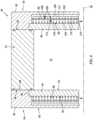
- FIG. 4 illustrates a cutaway view of a portion of the engine housing 46 including the rotor housing 52 and the side housing assemblies 54.
- Each of the side housing assemblies 54 includes a side housing body 82, a side plate 84, and an impingement cooling assembly 86.
- the side housing body 82 extends (e.g., axially extends) between and to an inner side 88 of the side housing body 82 and an outer side 90 of the side housing body 82.
- the side housing body 82 extends about (e.g., completely around) the rotational axis 28.
- the side housing body 82 includes a side housing body material.
- the side housing body material may form all or a substantial portion of the side housing body 82.
- the side housing body material may be metal or metal alloy material.
- the side housing body material may be a lightweight metal or metal alloy material having a relatively high thermal conductivity such as, but not limited to aluminum.
- the present disclosure is not limited to the use of a particular material or combination of materials for the side housing body material.
- the side plate 84 extends (e.g., axially extends relative to the rotational axis 28) between and to an inner side 92 of the side plate 84 and an outer side 94 of the side plate 84.
- the side plate 84 extends about (e.g., completely around) the rotational axis 28.
- the side plate 84 includes a perimeter edge 96 circumscribing the inner side 92 and the outer side 94.
- the side plate 84 (e.g., the perimeter edge 96) may have an epitrochoid shape similar to that of the rotor cavity 62.
- the side plate 84 is disposed axially between the rotor housing body 56 and the side housing body 82.
- the inner side 92 faces the rotor 48 and forms a portion of the rotor cavity 62.
- the inner side 92 (e.g., at the perimeter edge 96) may be disposed in contact with the first end 58 or the second end 60 of the rotor housing body and the outer side 94 may be disposed in contact with the inner side 88.
- the side plate 84 includes a side plate material.
- the side plate material may form all or a substantial portion of the side plate 84.
- the side plate material may be a metal or metal alloy material.
- the side plate material may alternatively be a ceramic material such as, but not limited to, silicon carbide (SiC).
- the side plate material may be the same as or different than the side housing body material. For example, the side plate material may be a harder material relative to the side housing body material.
- the present disclosure is not limited to the use of a particular material or combination of materials for the side plate material.
- the impingement cooling assembly 86 of FIG. 4 includes a perforated baffle plate 98.
- the baffle plate 98 may be formed by or otherwise disposed at (e.g., on, adjacent, or proximate) the side housing body 82.
- the baffle plate 98 may extend about (e.g., completely around) the rotational axis 28).
- the side housing body 82, the side plate 84, and the baffle plate 98 of FIG. 4 form a coolant passage 100 of the impingement cooling assembly 86.
- the coolant passage 100 includes an inlet plenum 102, an outlet plenum 104, and a plurality of impingement cooling holes 106 of the impingement cooling assembly 86.
- the inlet plenum 102 is formed between (e.g., axially between) the side housing body 82 and the baffle plate 98.
- the outlet plenum 104 is formed between (e.g., axially between) the baffle plate 98 and the side plate 84 (e.g., the outer side 94) with the outlet plenum 104 disposed axially inward of the inlet plenum 102.
- Each of the inlet plenum 102 and the outlet plenum 104 may extend about (e.g., completely around) the rotational axis 28 within the respective side housing assemblies 54.
- the baffle plate 98 forms the impingement cooling holes 106.
- Each of the impingement cooling holes 106 extends through the baffle plate 98 from the inlet plenum 102 to the outlet plenum 104.
- Each of the impingement cooling holes 106 extends between and to a cooling hole inlet 108 of each respective cooling hole 106 and a cooling hole outlet 110 of each respective cooling hole 106.
- the cooling hole inlet 108 is disposed at (e.g., on, adjacent, or proximate) the inlet plenum 102.
- the cooling hole outlet 110 is disposed at (e.g., on, adjacent, or proximate) the outlet plenum 104.
- the baffle plate 98 forms a nozzle 112 of each of the impingement cooling holes 106 at the cooling hole outlet 110.
- the nozzle 112 may extend into the outlet plenum 104 such that the cooling hole outlet 110 is spaced (e.g., axially spaced) from surrounding portions of the baffle plate 98.
- the nozzle 112 may alternatively be configured such that the cooling hole outlet 110 is flush with the surrounding portions of the baffle plate 98.
- the present disclosure is not limited to the foregoing exemplary configurations of the nozzle 112.
- the inlet plenum 102 is connected in fluid communication with a coolant inlet of the coolant passage 100 to direct a coolant into the inlet plenum 102 from the coolant inlet.
- the outlet plenum 104 is connected in fluid communication with a coolant outlet of the coolant passage 100 to direct the coolant out of the outlet plenum 104 to the coolant outlet.
- a coolant fluid is directed through the coolant passage 100 along a coolant flow path 114 as shown, for example, in FIG. 4 .
- the coolant include air, water, ethylene glycol, ammonia (NH 3 ), liquified or gaseous hydrogen (H 2 ), supercritical carbon dioxide (sCO 2 ) or other fluids in a supercritical state, and the like.
- the coolant is directed into the inlet plenum 102.
- the coolant from the inlet plenum 102 is directed through the impingement cooling holes 106, from the cooling hole inlet 108 to the cooling hole outlet 110 toward and onto the side plate 84 (e.g., the outer side 94).
- the nozzle 112 for each of the impingement cooling holes 106 forms a coolant jet 116 impinging (e.g., orthogonally impinging) on one or more surfaces of the side plate 84 at (e.g., on, adjacent, or proximate) the outer side 94. Impingement of the coolant on the side plate 84 cools the side plate 84, for example, by facilitating greater convective heat transfer from the side plate 84 to the coolant compared to at least some other conventional passage cooling configurations. After impinging on the side plate 84, the coolant flows through the outlet plenum 104 to exit the respective side housing assembly 54 (e.g., through the coolant outlet).
- the nozzle 112 for each of the impingement cooling holes 106 may have a free or a submerged and/or confined jet impingement configuration.
- the nozzle 112 may direct the coolant jet 116 into an ambient gas of the outlet plenum 104 (e.g., a free jet impingement configuration).
- the nozzle 112 may direct the coolant jet 116 into the outlet plenum 104 which outlet plenum 104 is filled or substantially filled by the coolant (e.g., a submerged and/or confined jet impingement configuration).
- the present disclosure is not limited to the foregoing exemplary jet impingement configurations).
- a density of the impingement cooling holes 106 (e.g., a number of impingement cooling holes relative to the outer side 94 surface area) and/or a flow rate of the coolant may be selected to control an average heat convective heat transfer coefficient of the side plate 84.
- the greater convective heat transfer of the side plate 84 facilitated by the impingement cooling assembly 86 may allow the engine 12 (see FIG. 1 ) to be operated with a higher heat flux from the rotor cavity 62 (e.g., a combustion chamber; see FIG. 3 ) while still maintaining the side plate 84 below safe operating temperature limits. Accordingly, the impingement cool assembly 86 may facilitate improved power density for the associated engine 12.
- FIG. 6 illustrates a cutaway, side view of another exemplary configuration of the side housing assembly 54 and the impingement cooling assembly 86.
- the impingement cooling assembly 86 of FIG. 6 includes a first baffle plate 118 and a second baffle plate 120.
- Each of the first baffle plate 118 and the second baffle plate 120 may be formed by or otherwise disposed at (e.g., on, adjacent, or proximate) the side housing body 82.
- the first baffle plate 118 and the second baffle plate 120 may be formed by a single baffle plate body (e.g., the first baffle plate 118 and the second baffle plate may be a unitary structure) or two discrete baffle plate bodies.
- Each of the first baffle plate 118 and the second baffle plate 120 may extend about (e.g., completely around) the rotational axis 28).
- the first baffle plate 118 is disposed axially outward of and axially spaced from the second baffle plate 120 relative to the rotational axis 28.
- the side housing body 82, the side plate 84, and the first baffle plate 118 and the second baffle plate 120 of FIG. 6 form a coolant passage 122 and a plurality of coolant cells 124 and of the impingement cooling assembly 86.
- the coolant passage 122 includes an inlet plenum 126 and an outlet plenum 128.
- the inlet plenum 126 is formed between (e.g., axially between) the side housing body 82 and the first baffle plate 118.
- the outlet plenum 128 is formed between (e.g., axially between) the first baffle plate 118 and the second baffle plate 120 with the outlet plenum 128 disposed axially inward of the inlet plenum 126.
- Each of the inlet plenum 126 and the outlet plenum 128 may extend about (e.g., completely around) the rotational axis 28 within the respective side housing assemblies 54.
- the inlet plenum 126 is connected in fluid communication with a coolant inlet of the coolant passage 122 to direct a coolant into the inlet plenum 126 from the coolant inlet.
- the outlet plenum 128 is connected in fluid communication with a coolant outlet of the coolant passage 122 to direct the coolant out of the outlet plenum 128 to the coolant outlet.
- Each of the coolant cells 124 extends along a cell axis 130.
- the cell axis 130 may be oriented parallel to or substantially parallel to the rotational axis 28.
- Each of the coolant cells 124 forms one or more impingement cooling holes 132, one or more coolant outlet holes 134, and an impingement cooling cavity 136.
- the coolant cell 124 of FIG. 6 forms one impingement cooling hole 132, which impingement cooling hole 132 extends along the cell axis 130.
- the present disclosure is not limited to any particular quantity or location for the impingement cooling holes 132 for the coolant cell 124.
- the impingement cooling hole 132 of FIG. 6 extends between and to the inlet plenum 126 and the impingement cooling cavity 136.
- the impingement cooling hole 132 of FIG. 6 extends between and to a cooling hole inlet 138 of the impingement cooling hole 132 and a cooling hole outlet 140 of the impingement cooling hole 132.
- the cooling hole inlet 138 is disposed at (e.g., on, adjacent, or proximate) the first baffle plate 118 (e.g., an outer axial side of the first baffle plate 118).
- the cooling hole outlet 140 is disposed at (e.g., on, adjacent, or proximate) the second baffle plate 120 (e.g., an inner axial side of the second baffle plate 120).
- the impingement cooling hole sidewall 142 extending between and to the first baffle plate 118 and the second baffle plate 120 to form a portion of the impingement cooling hole 132 between and to the first baffle plate 118 and the second baffle plate 120.
- the impingement cooling hole sidewall 142 may be formed by the first baffle plate 118 and/or the second baffle plate 120 or otherwise mounted between and connected to the first baffle plate 118 and the second baffle plate 120.
- the coolant cell 124 of FIG. 6 forms a nozzle 144 of the impingement cooling hole 132 at the cooling hole outlet 140.
- the nozzle 144 may be configured similar to the nozzle 112 (see FIGS. 4 , 5A, and 5B ), as previously discussed.
- the coolant cell 124 of FIG. 6 forms the coolant outlet holes 134 radially outward of the impingement cooling hole 132 and the cell axis 130.
- the coolant outlet holes 134 may be circumferentially arrayed or distributed about the cell axis 130.
- Each of the coolant outlet holes 134 of FIG. 6 extends between and to impingement cooling cavity 136 and the outlet plenum 128.
- Each of the coolant outlet holes 134 extends between and to hole inlet 146 of the respective coolant outlet hole 134 and a hole outlet 148 of the respective coolant outlet hole 134.
- the coolant outlet holes 134 of FIG. 6 extend through the second baffle plate 120 between the hole inlet 146 and the hole outlet 148.
- the hole inlet 146 is disposed at (on, adjacent, or proximate) the impingement cooling cavity 136.
- the hole outlet 148 is disposed at (e.g., on, adjacent, or proximate) the outlet plenum 128.
- the impingement cooling cavity 136 is formed by and between (e.g., axially between) the second baffle plate 120 and the side plate 84.
- the impingement cooling cavity 136 is further formed by a cooling cavity sidewall 150 of the coolant cell 124 of FIG. 6 .
- the cooling cavity sidewall 150 extends about (e.g., completely around) the cell axis 130 to circumscribe the impingement cooling cavity 136.
- the cooling cavity sidewall 150 extends between and to the second baffle plate 120 and the side plate 84 (e.g., the outer side 94).
- the cooling cavity sidewall 150 may be formed by the second baffle plate 120, mounted to the second baffle plate 120, or otherwise disposed between and connected to the second baffle plate 120 and the side plate 84.
- the coolant fluid is directed through the coolant passage 122 along a coolant flow path 152 as shown, for example, in FIG. 6 .
- the coolant is directed into the inlet plenum 126.
- the coolant from the inlet plenum 126 is directed through the impingement cooling holes 132, from the cooling hole inlet 138 to the cooling hole outlet 140 toward and onto the side plate 84 (e.g., the outer side 94).
- the nozzle 144 for each of the impingement cooling holes 132 forms a coolant jet 154 impinging (e.g., orthogonally impinging) on one or more surfaces of the side plate 84 at (e.g., on, adjacent, or proximate) the outer side 94 and within the impingement cooling cavity 136. Impingement of the coolant on the side plate 84 cools the side plate 84, for example, by facilitating greater convective heat transfer from the side plate 84, as previously discussed. After impinging on the side plate 84, the coolant flows from the impingement cooling cavity 136, through the coolant outlet holes 134, and through the outlet plenum 128 to exit the respective side housing assembly 54 (e.g., through the coolant outlet).
- Impingement of the coolant on the side plate 84 cools the side plate 84, for example, by facilitating greater convective heat transfer from the side plate 84, as previously discussed.
- the coolant flows from the impingement cooling cavity 136
- FIG. 7 illustrates a cutaway, side view of another exemplary configuration of the side housing assembly 54 and the impingement cooling assembly 86.
- the side housing body 82 and the side plate 84 may be a unitary structure 156.
- the term "unitary structure" as used herein means a single component, wherein all elements of the side housing body 82 and the side plate 84 are an inseparable body (e.g., formed of a single material, or a weldment of independent elements, etc.).
- the unitary structure 156 of the side housing body 82 and the side plate 84 may be formed in a single process (e.g., an additive manufacturing process, etc.) or may be a weldment of the side housing body 82 and the side plate 84.
- the unitary structure 156 may facilitate simplified manufacturing and assembly of the side housing assembly 54.
- the side housing body 82 and the side plate 84 forming the unitary structure 156 may obviate the use of seals (e.g., coolant fluid seals) between the side housing body 82 and the side plate 84, between the side housing body 82 and one or more baffle plates, and/or between other components of the side housing assembly 54.
- seals e.g., coolant fluid seals
- side housing body 82 and/or side plate 84 wear caused by relative sliding or other movement between the side housing body 82 and the side plate 84 may be eliminated.
- the impingement cooling assembly 86 of FIG. 7 includes a first baffle plate 158 and a second baffle plate 160.
- Each of the first baffle plate 158 and the second baffle plate 160 may be formed by the unitary structure 156 (e.g., the first baffle plate 158 and the second baffle plate 160 may be portions of the unitary structure 156).
- Each of the first baffle plate 158 and the second baffle plate 160 may extend about (e.g., completely around) the rotational axis 28).
- the first baffle plate 158 is disposed axially outward of and axially spaced from the second baffle plate 160 relative to the rotational axis 28.
- the unitary structure 156 and its side housing body 82, side plate 84, first baffle plate 158, and the second baffle plate 160 of FIG. 7 form a coolant passage 162 and a plurality of coolant cells 164 and of the impingement cooling assembly 86.
- the coolant passage 162 includes an inlet plenum 166 and an outlet plenum 168.
- the inlet plenum 166 is formed between (e.g., axially between) the first baffle plate 158 and the second baffle plate 160.
- the outlet plenum 168 is formed between (e.g., axially between) the side housing body 82 and the first baffle plate 158 with the outlet plenum 168 disposed axially outward of the inlet plenum 166.
- Each of the inlet plenum 166 and the outlet plenum 168 may extend about (e.g., completely around) the rotational axis 28 within the respective side housing assemblies 54.
- the inlet plenum 166 is connected in fluid communication with a coolant inlet of the coolant passage 162 to direct a coolant into the inlet plenum 166 from the coolant inlet.
- the outlet plenum 168 is connected in fluid communication with a coolant outlet of the coolant passage 162 to direct the coolant out of the outlet plenum 168 to the coolant outlet.
- Each of the coolant cells 164 extends along a cell axis 170.
- the cell axis 170 may be oriented parallel to or substantially parallel to the rotational axis 28.
- Each of the coolant cells 164 forms one or more impingement cooling holes 172, one or more coolant outlet holes 174, and an impingement cooling cavity 176.
- the coolant cell 164 of FIG. 7 forms one impingement cooling hole 172, which impingement cooling hole 172 extends along the cell axis 170.
- the present disclosure is not limited to any particular quantity or location for the impingement cooling holes 172 for the coolant cell 164.
- the impingement cooling hole 172 of FIG. 7 extends between and to the inlet plenum 166 and the impingement cooling cavity 176.
- the impingement cooling hole 172 of FIG. 7 extends between and to a cooling hole inlet 178 of the impingement cooling hole 172 and a cooling hole outlet 180 of the impingement cooling hole 172.
- the cooling hole inlet 178 is disposed at (e.g., on, adjacent, or proximate) the second baffle plate 160 (e.g., an outer axial side of the second baffle plate 160).
- the cooling hole outlet 180 is disposed at (e.g., on, adjacent, or proximate) the impingement cooling cavity 176.
- the coolant cell 164 of FIG. 7 forms a nozzle 182 of the impingement cooling hole 172 at the cooling hole outlet 180.
- the nozzle 182 may be configured similar to the nozzle 112 (see FIGS. 4 , 5A, and 5B ), as previously discussed.
- the coolant cell 164 of FIG. 7 forms the coolant outlet holes 174 radially outward of the impingement cooling hole 172 and the cell axis 170.
- the coolant outlet holes 174 may be circumferentially arrayed or distributed about the cell axis 170.
- Each of the coolant outlet holes 174 of FIG. 7 extends between and to impingement cooling cavity 176 and the outlet plenum 168.
- Each of the coolant outlet holes 174 extends between and to hole inlet 184 of the respective coolant outlet hole 174 and a hole outlet 186 of the respective coolant outlet hole 174.
- the coolant outlet holes 174 of FIG. 7 extend through the first baffle plate 158 and the second baffle plate 160 between the hole inlet 184 and the hole outlet 186.
- the hole inlet 184 is disposed at (on, adjacent, or proximate) the impingement cooling cavity 176.
- the hole outlet 186 is disposed at (e.g., on, adjacent, or proximate) the outlet plenum 168.
- the coolant cell 164 of FIG. 7 includes an outlet hole sidewall 188 for each of the coolant outlet holes 174.
- the outlet hole sidewall 188 extends between and to the first baffle plate 158 and the second baffle plate 160 to form a portion of a respective one of the coolant outlet holes 174 between and to the first baffle plate 158 and the second baffle plate 160.
- the outlet hole sidewall 188 may be formed by the unitary structure 156 (e.g., the outlet hole sidewall 188 may be a portion of the unitary structure 156).
- the impingement cooling cavity 176 is formed by and between (e.g., axially between) the second baffle plate 160 and the side plate 84.
- the impingement cooling cavity 176 is further formed by a cooling cavity sidewall 190 of the coolant cell 164 of FIG. 7 .
- the cooling cavity sidewall 190 extends about (e.g., completely around) the cell axis 170 to circumscribe the impingement cooling cavity 176.
- the cooling cavity sidewall 190 extends between and to the second baffle plate 160 and the side plate 84 (e.g., the outer side 94).
- the cooling cavity sidewall 190 may be formed by the unitary structure 156 (e.g., the cooling cavity sidewall 190 may be a portion of the unitary structure 156).
- the coolant fluid is directed through the coolant passage 162 along a coolant flow path 192 as shown, for example, in FIG. 7 .
- the coolant is directed into the inlet plenum 166.
- the coolant from the inlet plenum 166 is directed through the impingement cooling holes 172, from the cooling hole inlet 178 to the cooling hole outlet 180 toward and onto the side plate 84 (e.g., the outer side 94).
- the nozzle 182 for each of the impingement cooling holes 172 forms a coolant jet 194 impinging (e.g., orthogonally impinging) on one or more surfaces of the side plate 84 at (e.g., on, adjacent, or proximate) the outer side 94 and within the impingement cooling cavity 176. Impingement of the coolant on the side plate 84 cools the side plate 84, for example, by facilitating greater convective heat transfer from the side plate 84, as previously discussed. After impinging on the side plate 84, the coolant flows from the impingement cooling cavity 176, through the coolant outlet holes 174, and through the outlet plenum 168 to exit the respective side housing assembly 54 (e.g., through the coolant outlet).
- Impingement of the coolant on the side plate 84 cools the side plate 84, for example, by facilitating greater convective heat transfer from the side plate 84, as previously discussed.
- the coolant flows from the impingement cooling cavity 176
- any one of these structures may describe the operations as a sequential process, many of the operations can be performed in parallel or concurrently.
- the order of the operations may be rearranged.
- a process may correspond to a method, a function, a procedure, a subroutine, a subprogram, etc.
Landscapes
- Engineering & Computer Science (AREA)
- Mechanical Engineering (AREA)
- General Engineering & Computer Science (AREA)
- Turbine Rotor Nozzle Sealing (AREA)
Applications Claiming Priority (1)
| Application Number | Priority Date | Filing Date | Title |
|---|---|---|---|
| US18/512,779 US12168933B1 (en) | 2023-11-17 | 2023-11-17 | Impingement cooling assembly for an aircraft rotary engine housing |
Publications (1)
| Publication Number | Publication Date |
|---|---|
| EP4556682A1 true EP4556682A1 (fr) | 2025-05-21 |
Family
ID=93566239
Family Applications (1)
| Application Number | Title | Priority Date | Filing Date |
|---|---|---|---|
| EP24213682.8A Pending EP4556682A1 (fr) | 2023-11-17 | 2024-11-18 | Ensemble de refroidissement par impact pour un carter de moteur rotatif d'aéronef |
Country Status (2)
| Country | Link |
|---|---|
| US (1) | US12168933B1 (fr) |
| EP (1) | EP4556682A1 (fr) |
Citations (4)
| Publication number | Priority date | Publication date | Assignee | Title |
|---|---|---|---|---|
| US3007460A (en) * | 1960-03-29 | 1961-11-07 | Curtiss Wright Corp | Cooling arrangement for rotary mechanisms |
| DE102008015031A1 (de) * | 2008-03-17 | 2009-09-24 | Wankel Super Tec Gmbh | Gehäuse für einen Kreiskolbenmotor und Kreiskolbenmotor |
| AT510749B1 (de) * | 2010-11-18 | 2012-09-15 | Avl List Gmbh | Kreiskolbenbrennkraftmaschine |
| DE102014017849A1 (de) * | 2014-12-02 | 2016-06-02 | Kkm Gmbh | Kreiskolbenbrennkraftmaschine |
Family Cites Families (7)
| Publication number | Priority date | Publication date | Assignee | Title |
|---|---|---|---|---|
| US3280802A (en) * | 1963-10-26 | 1966-10-25 | Nsu Motorenwerke Ag | Fluid cooled housing wall for internal combustion engines |
| US3298330A (en) * | 1964-04-22 | 1967-01-17 | Yanmar Diesel Engine Co | Rotary piston engine |
| DE2325249A1 (de) * | 1973-05-18 | 1974-12-05 | Daimler Benz Ag | Rotationskolben-brennkraftmaschine in trochoidenbauart |
| DE10124561A1 (de) * | 2000-05-27 | 2001-11-29 | Brandenburgische Forschungs Un | Kreiskolbenmotor in Trochoidenbauart |
| US10072566B2 (en) | 2015-12-18 | 2018-09-11 | Pratt & Whitney Canada Corp. | Rotary engine casing with seal engaging plate having mating surface defining a fluid cavity |
| US11613995B2 (en) | 2018-12-20 | 2023-03-28 | Pratt & Whitney Canada Corp. | Rotary engine with housing having silicon carbide plate |
| US11761376B1 (en) | 2022-11-11 | 2023-09-19 | Pratt & Whitney Canada Corp. | Side plate for rotary engine |
-
2023
- 2023-11-17 US US18/512,779 patent/US12168933B1/en active Active
-
2024
- 2024-11-18 EP EP24213682.8A patent/EP4556682A1/fr active Pending
Patent Citations (4)
| Publication number | Priority date | Publication date | Assignee | Title |
|---|---|---|---|---|
| US3007460A (en) * | 1960-03-29 | 1961-11-07 | Curtiss Wright Corp | Cooling arrangement for rotary mechanisms |
| DE102008015031A1 (de) * | 2008-03-17 | 2009-09-24 | Wankel Super Tec Gmbh | Gehäuse für einen Kreiskolbenmotor und Kreiskolbenmotor |
| AT510749B1 (de) * | 2010-11-18 | 2012-09-15 | Avl List Gmbh | Kreiskolbenbrennkraftmaschine |
| DE102014017849A1 (de) * | 2014-12-02 | 2016-06-02 | Kkm Gmbh | Kreiskolbenbrennkraftmaschine |
Also Published As
| Publication number | Publication date |
|---|---|
| US12168933B1 (en) | 2024-12-17 |
Similar Documents
| Publication | Publication Date | Title |
|---|---|---|
| CN108138654B (zh) | 具有组合的发动机和冷却排气的涡轮螺旋桨发动机组件 | |
| CA2961115C (fr) | Systeme de commande directionnelle et methode de fourniture de commande directionnelle | |
| EP3199767B1 (fr) | Ensemble moteur ayant un carter de support de turbine | |
| CN107636295B (zh) | 具有选择阀的发动机进气组件 | |
| CN107532548B (zh) | 具有公共入口的复合发动机组件 | |
| EP3747766B1 (fr) | Groupe motopropulseur d'avion | |
| EP3747767B1 (fr) | Groupe motopropulseur d'avion | |
| EP4491847A2 (fr) | Carter de moteur rotatif avec ensemble d'étanchéité | |
| EP4491846A2 (fr) | Carter de moteur rotatif avec un ensemble d'étanchéité | |
| EP4556682A1 (fr) | Ensemble de refroidissement par impact pour un carter de moteur rotatif d'aéronef | |
| CA3254169A1 (fr) | Ensemble de refroidissement d’incidence pour un carter de moteur à piston rotatif d’un aéronef | |
| EP4610525A2 (fr) | Elément d'étanchéité nervuré pour groupe motopropulseur d'aéronef | |
| EP4442958B1 (fr) | Ensemble rotor pour moteur rotatif | |
| EP4442957B1 (fr) | Rotor pour moteur rotatif | |
| EP4450784B1 (fr) | Moteur à combustion interne avec un ou plusieurs composants de chambre pilote en céramique | |
| EP4534827A1 (fr) | Grille de protection d'entrée adaptée à la périphérie pour une entrée de moteur d'aéronef | |
| US12590551B1 (en) | Oil tank return for an aircraft engine oil system | |
| EP4722496A1 (fr) | Appareil pour un moteur à turbine | |
| US20260092538A1 (en) | Scavenge pump assembly for an aircraft engine oil system |
Legal Events
| Date | Code | Title | Description |
|---|---|---|---|
| PUAI | Public reference made under article 153(3) epc to a published international application that has entered the european phase |
Free format text: ORIGINAL CODE: 0009012 |
|
| STAA | Information on the status of an ep patent application or granted ep patent |
Free format text: STATUS: THE APPLICATION HAS BEEN PUBLISHED |
|
| AK | Designated contracting states |
Kind code of ref document: A1 Designated state(s): AL AT BE BG CH CY CZ DE DK EE ES FI FR GB GR HR HU IE IS IT LI LT LU LV MC ME MK MT NL NO PL PT RO RS SE SI SK SM TR |
|
| STAA | Information on the status of an ep patent application or granted ep patent |
Free format text: STATUS: REQUEST FOR EXAMINATION WAS MADE |
|
| 17P | Request for examination filed |
Effective date: 20251121 |
|
| GRAP | Despatch of communication of intention to grant a patent |
Free format text: ORIGINAL CODE: EPIDOSNIGR1 |
|
| STAA | Information on the status of an ep patent application or granted ep patent |
Free format text: STATUS: GRANT OF PATENT IS INTENDED |