EP4556700A2 - Aube directrice d'entrée de compresseur fluidique - Google Patents
Aube directrice d'entrée de compresseur fluidique Download PDFInfo
- Publication number
- EP4556700A2 EP4556700A2 EP24213340.3A EP24213340A EP4556700A2 EP 4556700 A2 EP4556700 A2 EP 4556700A2 EP 24213340 A EP24213340 A EP 24213340A EP 4556700 A2 EP4556700 A2 EP 4556700A2
- Authority
- EP
- European Patent Office
- Prior art keywords
- water
- injectors
- airflow
- flow
- recited
- Prior art date
- Legal status (The legal status is an assumption and is not a legal conclusion. Google has not performed a legal analysis and makes no representation as to the accuracy of the status listed.)
- Pending
Links
Images


Classifications
-
- F—MECHANICAL ENGINEERING; LIGHTING; HEATING; WEAPONS; BLASTING
- F02—COMBUSTION ENGINES; HOT-GAS OR COMBUSTION-PRODUCT ENGINE PLANTS
- F02C—GAS-TURBINE PLANTS; AIR INTAKES FOR JET-PROPULSION PLANTS; CONTROLLING FUEL SUPPLY IN AIR-BREATHING JET-PROPULSION PLANTS
- F02C3/00—Gas-turbine plants characterised by the use of combustion products as the working fluid
- F02C3/04—Gas-turbine plants characterised by the use of combustion products as the working fluid having a turbine driving a compressor
- F02C3/06—Gas-turbine plants characterised by the use of combustion products as the working fluid having a turbine driving a compressor the compressor comprising only axial stages
-
- F—MECHANICAL ENGINEERING; LIGHTING; HEATING; WEAPONS; BLASTING
- F02—COMBUSTION ENGINES; HOT-GAS OR COMBUSTION-PRODUCT ENGINE PLANTS
- F02C—GAS-TURBINE PLANTS; AIR INTAKES FOR JET-PROPULSION PLANTS; CONTROLLING FUEL SUPPLY IN AIR-BREATHING JET-PROPULSION PLANTS
- F02C3/00—Gas-turbine plants characterised by the use of combustion products as the working fluid
- F02C3/20—Gas-turbine plants characterised by the use of combustion products as the working fluid using a special fuel, oxidant, or dilution fluid to generate the combustion products
- F02C3/30—Adding water, steam or other fluids for influencing combustion, e.g. to obtain cleaner exhaust gases
-
- F—MECHANICAL ENGINEERING; LIGHTING; HEATING; WEAPONS; BLASTING
- F02—COMBUSTION ENGINES; HOT-GAS OR COMBUSTION-PRODUCT ENGINE PLANTS
- F02C—GAS-TURBINE PLANTS; AIR INTAKES FOR JET-PROPULSION PLANTS; CONTROLLING FUEL SUPPLY IN AIR-BREATHING JET-PROPULSION PLANTS
- F02C3/00—Gas-turbine plants characterised by the use of combustion products as the working fluid
- F02C3/20—Gas-turbine plants characterised by the use of combustion products as the working fluid using a special fuel, oxidant, or dilution fluid to generate the combustion products
- F02C3/30—Adding water, steam or other fluids for influencing combustion, e.g. to obtain cleaner exhaust gases
- F02C3/305—Increasing the power, speed, torque or efficiency of a gas turbine or the thrust of a turbojet engine by injecting or adding water, steam or other fluids
-
- F—MECHANICAL ENGINEERING; LIGHTING; HEATING; WEAPONS; BLASTING
- F02—COMBUSTION ENGINES; HOT-GAS OR COMBUSTION-PRODUCT ENGINE PLANTS
- F02C—GAS-TURBINE PLANTS; AIR INTAKES FOR JET-PROPULSION PLANTS; CONTROLLING FUEL SUPPLY IN AIR-BREATHING JET-PROPULSION PLANTS
- F02C7/00—Features, components parts, details or accessories, not provided for in, or of interest apart form groups F02C1/00 - F02C6/00; Air intakes for jet-propulsion plants
- F02C7/12—Cooling of plants
- F02C7/14—Cooling of plants of fluids in the plant, e.g. lubricant or fuel
- F02C7/141—Cooling of plants of fluids in the plant, e.g. lubricant or fuel of working fluid
-
- F—MECHANICAL ENGINEERING; LIGHTING; HEATING; WEAPONS; BLASTING
- F02—COMBUSTION ENGINES; HOT-GAS OR COMBUSTION-PRODUCT ENGINE PLANTS
- F02C—GAS-TURBINE PLANTS; AIR INTAKES FOR JET-PROPULSION PLANTS; CONTROLLING FUEL SUPPLY IN AIR-BREATHING JET-PROPULSION PLANTS
- F02C7/00—Features, components parts, details or accessories, not provided for in, or of interest apart form groups F02C1/00 - F02C6/00; Air intakes for jet-propulsion plants
- F02C7/12—Cooling of plants
- F02C7/14—Cooling of plants of fluids in the plant, e.g. lubricant or fuel
- F02C7/141—Cooling of plants of fluids in the plant, e.g. lubricant or fuel of working fluid
- F02C7/143—Cooling of plants of fluids in the plant, e.g. lubricant or fuel of working fluid before or between the compressor stages
-
- F—MECHANICAL ENGINEERING; LIGHTING; HEATING; WEAPONS; BLASTING
- F02—COMBUSTION ENGINES; HOT-GAS OR COMBUSTION-PRODUCT ENGINE PLANTS
- F02C—GAS-TURBINE PLANTS; AIR INTAKES FOR JET-PROPULSION PLANTS; CONTROLLING FUEL SUPPLY IN AIR-BREATHING JET-PROPULSION PLANTS
- F02C7/00—Features, components parts, details or accessories, not provided for in, or of interest apart form groups F02C1/00 - F02C6/00; Air intakes for jet-propulsion plants
- F02C7/12—Cooling of plants
- F02C7/14—Cooling of plants of fluids in the plant, e.g. lubricant or fuel
- F02C7/141—Cooling of plants of fluids in the plant, e.g. lubricant or fuel of working fluid
- F02C7/143—Cooling of plants of fluids in the plant, e.g. lubricant or fuel of working fluid before or between the compressor stages
- F02C7/1435—Cooling of plants of fluids in the plant, e.g. lubricant or fuel of working fluid before or between the compressor stages by water injection
-
- F—MECHANICAL ENGINEERING; LIGHTING; HEATING; WEAPONS; BLASTING
- F02—COMBUSTION ENGINES; HOT-GAS OR COMBUSTION-PRODUCT ENGINE PLANTS
- F02C—GAS-TURBINE PLANTS; AIR INTAKES FOR JET-PROPULSION PLANTS; CONTROLLING FUEL SUPPLY IN AIR-BREATHING JET-PROPULSION PLANTS
- F02C7/00—Features, components parts, details or accessories, not provided for in, or of interest apart form groups F02C1/00 - F02C6/00; Air intakes for jet-propulsion plants
- F02C7/12—Cooling of plants
- F02C7/16—Cooling of plants characterised by cooling medium
-
- F—MECHANICAL ENGINEERING; LIGHTING; HEATING; WEAPONS; BLASTING
- F02—COMBUSTION ENGINES; HOT-GAS OR COMBUSTION-PRODUCT ENGINE PLANTS
- F02C—GAS-TURBINE PLANTS; AIR INTAKES FOR JET-PROPULSION PLANTS; CONTROLLING FUEL SUPPLY IN AIR-BREATHING JET-PROPULSION PLANTS
- F02C7/00—Features, components parts, details or accessories, not provided for in, or of interest apart form groups F02C1/00 - F02C6/00; Air intakes for jet-propulsion plants
- F02C7/12—Cooling of plants
- F02C7/16—Cooling of plants characterised by cooling medium
- F02C7/18—Cooling of plants characterised by cooling medium the medium being gaseous, e.g. air
-
- F—MECHANICAL ENGINEERING; LIGHTING; HEATING; WEAPONS; BLASTING
- F02—COMBUSTION ENGINES; HOT-GAS OR COMBUSTION-PRODUCT ENGINE PLANTS
- F02C—GAS-TURBINE PLANTS; AIR INTAKES FOR JET-PROPULSION PLANTS; CONTROLLING FUEL SUPPLY IN AIR-BREATHING JET-PROPULSION PLANTS
- F02C7/00—Features, components parts, details or accessories, not provided for in, or of interest apart form groups F02C1/00 - F02C6/00; Air intakes for jet-propulsion plants
- F02C7/12—Cooling of plants
- F02C7/16—Cooling of plants characterised by cooling medium
- F02C7/18—Cooling of plants characterised by cooling medium the medium being gaseous, e.g. air
- F02C7/185—Cooling means for reducing the temperature of the cooling air or gas
-
- F—MECHANICAL ENGINEERING; LIGHTING; HEATING; WEAPONS; BLASTING
- F05—INDEXING SCHEMES RELATING TO ENGINES OR PUMPS IN VARIOUS SUBCLASSES OF CLASSES F01-F04
- F05D—INDEXING SCHEME FOR ASPECTS RELATING TO NON-POSITIVE-DISPLACEMENT MACHINES OR ENGINES, GAS-TURBINES OR JET-PROPULSION PLANTS
- F05D2220/00—Application
- F05D2220/30—Application in turbines
- F05D2220/32—Application in turbines in gas turbines
- F05D2220/323—Application in turbines in gas turbines for aircraft propulsion, e.g. jet engines
-
- F—MECHANICAL ENGINEERING; LIGHTING; HEATING; WEAPONS; BLASTING
- F05—INDEXING SCHEMES RELATING TO ENGINES OR PUMPS IN VARIOUS SUBCLASSES OF CLASSES F01-F04
- F05D—INDEXING SCHEME FOR ASPECTS RELATING TO NON-POSITIVE-DISPLACEMENT MACHINES OR ENGINES, GAS-TURBINES OR JET-PROPULSION PLANTS
- F05D2260/00—Function
- F05D2260/20—Heat transfer, e.g. cooling
- F05D2260/212—Heat transfer, e.g. cooling by water injection
-
- F—MECHANICAL ENGINEERING; LIGHTING; HEATING; WEAPONS; BLASTING
- F05—INDEXING SCHEMES RELATING TO ENGINES OR PUMPS IN VARIOUS SUBCLASSES OF CLASSES F01-F04
- F05D—INDEXING SCHEME FOR ASPECTS RELATING TO NON-POSITIVE-DISPLACEMENT MACHINES OR ENGINES, GAS-TURBINES OR JET-PROPULSION PLANTS
- F05D2270/00—Control
- F05D2270/01—Purpose of the control system
- F05D2270/08—Purpose of the control system to produce clean exhaust gases
Definitions
- the present disclosure relates generally to an intercooled turbine engine where water is injected into a compressor section.
- Gas turbine engines compress incoming core airflow, mix the compressed airflow with fuel that is ignited in a combustor to generate a high energy exhaust gas flow.
- Inlet guide vanes are utilized to set an angle of air flow into compressor sections. The angle of airflow may vary based on engine operating points. Gaps around movable inlet guide vanes generate secondary losses that reduce overall compressor efficiency.
- Turbine engine manufacturers continue to seek further improvements to engine performance including improvements to reduce environmental impact while improving propulsive efficiencies.
- a propulsion system for an aircraft includes, among other possible things, a core engine that includes a core flow path where air is compressed in a compressor section, communicated to a combustor section, mixed with fuel, and ignited to generate a high energy gas flow that is expanded through a turbine section.
- the compressor section includes a low pressure compressor that is upstream of a high pressure compressor.
- An intercooling system is configured to inject water into the compressor section to reduce a temperature of a core airflow within the core flow path.
- the intercooling system includes a plurality of injectors for injecting water at a water injection angle relative to an airflow to generate a defined swirl of a combined airflow and water to the compressor section.
- each of the plurality of injectors are movable to adjust the water injection angle relative to the airflow.
- a mass of water through each of the plurality of injectors is variable to adjust the defined swirl of the combined airflow and water into the compressor section.
- the water injection angle includes a circumferential component and an axial component.
- the water injection angle for each of the plurality of injectors is the same.
- the water injection angle for at least one of the plurality of injectors varies relative to others of the plurality of injectors.
- the propulsion system includes a synchronization assembly to which the plurality of injectors is attached.
- the synchronization assembly is actuatable to vary the water injection angle.
- the propulsion system further includes an annular passage for directing an airflow from an exit of the low pressure compressor to an inlet of the high pressure compressor.
- the plurality of injectors is disposed within the annular passage for generating the defined swirl of the combined airflow and water through the annular passage to the inlet of the high pressure compressor.
- the plurality of injectors are spaced circumferentially apart about an outer radial surface of the annular passage.
- the plurality of injectors are spaced circumferentially apart about an inner radial surface of the annular passage.
- the plurality of injectors are spaced circumferentially apart about both an inner radial surface and an outer radial surface of the annular passage.
- the propulsion system further includes a plurality of exit guide vanes within the annular passage for directing airflow from the exit of the low pressure compressor.
- the plurality of injectors are mounted to corresponding ones of the plurality of exit guide vanes.
- each of the plurality of injectors are movable relative to the corresponding ones of the plurality of exit guide vanes for adjusting the water injection angle.
- An intercooling system for a turbine engine includes, among other possible things, a condenser that is arranged along a core flow path and configured to extract water from an exhaust gas flow, a pump where water from the condenser is pressurized, and a plurality of injectors where a pressurized water flow is injected into the core flow path within a compressor section.
- the plurality of injectors are movable to vary a water injection angle relative to an inlet airflow and generate a defined swirl of a combined airflow and water to an inlet of the compressor section.
- the intercooling system includes a synchronization ring to which the plurality of injectors are attached.
- the synchronization ring is movable to vary the water injection angle.
- the compressor section includes a low pressure compressor that is upstream of a high pressure compressor with an annular passage for directing an airflow from an exit of the low pressure compressor to an inlet of the high pressure compressor.
- the plurality of injectors are spaced circumferentially apart about at least one of an outer radial surface and an inner radial surface of the annular passage.
- the intercooling system further includes a plurality of exit guide vanes within the annular passage for directing airflow from the exit of the low pressure compressor.
- the plurality of injectors are mounted to corresponding ones of the plurality of exit guide vanes.
- a method of operating a compressor section of a turbine engine includes, among other possible things, generating a pressurized airflow through a first compressor section, injecting a pressurized water flow at a water injection angle relative to the pressurized airflow that is generated in the first compressor section to generate a combined pressurized air and water flow with a resultant swirl angular flow component, communicating the combined pressurized air and water flow to a second compressor section downstream of the first compressor section, and varying the water injection angle based on an engine operating point.
- the method further includes adjusting a pressure of water that is injected to vary the resultant swirl angular flow component.
- the example propulsion system 20 is a hydrogen steam injected inter-cooled turbine engine with a core engine 22.
- the core engine 22 includes a core airflow path C through a fan 24, a compressor section 26, a combustor 28 and a turbine section 30 arranged along an engine longitudinal axis A.
- a fuel system 32 includes a hydrogen (H 2 ) fuel storage tank 34 and a fuel pump 36 to generate a fuel flow 60.
- the fan 24 drives inlet air as a core flow 38 into the compressor section 26. In the compressor section 26, the core flow 38 is compressed and communicated to the combustor 28.
- the core flow 38 is mixed with the hydrogen (H 2 ) fuel flow 60 and ignited to generate a high energy gas flow 40 that expands through the turbine section 30 where energy is extracted and utilized to drive the fan 24 and the compressor section 26.
- a bypass flow 92 may flow through the fan 24 and a bypass flow path B around the remaining components of the core engine 22.
- the high energy gas flow 40 is exhausted from the turbine section 30 and communicated through a condenser 42 and an evaporator 44.
- the condenser 42 cools a portion of the exhaust gas flow 40 to extract water 46 that is stored in a tank 48.
- a pump 50 moves water through the evaporator 44.
- heat from the exhaust gas flow 40 is used to transform at least a portion of water into a steam flow 58.
- the steam flow 58 is injected into the combustor 28 or other locations within the core flow path C.
- the example core engine 22 has an increased power output from the injected steam due to an increasing mass flow through the turbine section 30 without a corresponding increase in work from the compressor section 26.
- An example engine operation cycle may include up to (or more than) 35% steam-air-ratios (SAR) and may be assisted by a multiple fold (e.g., 2x, 3x, etc.) increase in moisture from burning H 2 as the fuel.
- SAR steam-air-ratios
- the intercooling system 25 provides an intercooling flow of water 52 may be communicated to the compressor section 26 to reduce a temperature of the core airflow 26 and increase mass flow. Reduced temperatures and increased mass flow provided by injection of water increases compressor efficiency. Longer resident times for the injected water are desirable to maximize the amount of water evaporated, that in turn, maximizes cooling of the pressurized airflow within the compressor section 26.
- the example compressor section 26 includes a low pressure compressor (LPC) 62 and a high pressure compressor (HPC) 64 separated by an annular passage 70.
- the turbine section 30 includes a high pressure turbine (HPT) 66, and a low pressure turbine (LPT) 68.
- the turbines 66 and 68 are coupled to a corresponding compressor section 62, 64.
- the HPT 66 is coupled to drive the HPC 64.
- the LPT 68 is coupled to drive the LPC 62 and the fan 24.
- the LPT 68 may be coupled to the fan 24 via a gearbox that is configured to reduce the speed of the shaft relative to the LPT 68 and/or the LPC 62.
- the example core engine 22 is described and shown by way of example as a two-spool engine, other engine configurations and architectures may also benefit from this disclosure and are within the contemplation and scope of this disclosure.
- the example intercooling system 25 includes an intercooling pump 54 that generates a pressurized intercooling water flow 56 that is injected into a location between the LPC 62 and the HPC 64. Moreover, the example intercooling system 25 provides swirling of flows between the LPC 62 and the HPC 64 to maximize cooling by increasing resident time and evaporation.
- Previous compressor sections would utilize a variable inlet guide vane at the inlet to direct airflow into the HPC.
- Such inlet guide vanes are a potential source of efficiency losses because some airflow may leak past the inlet guide vane.
- Disclosed example embodiments eliminate the inlet guide vane and utilize water injection for intercooling to direct and generate desired flows into the HPC.
- the example intercooling system 25 is shown schematically and provides for water 88 to be injected into the passage 70 through one or more injectors 84.
- Pressurized airflow 80 through an exit 76 of the LPC 62 is communicated through the passage 70 to an inlet 78 for the HPC 64.
- An angle of the pressurized airflow 80 through the inlet 78 is determined first by the exit guide vanes 96.
- the exit guide vanes 96 straighten the airflow 80 for introduction into the passage 70.
- the direction of the airflow 80 is modified by the direction of injected intercooling waterflow 88 to generate a combined water and air flow indicated at 90 in a resultant direction.
- the resultant direction is different than either the direction of the airflow 80 and the injection of the water flow 88.
- the direction of the combined air and water flow 90 through the inlet 78 to the HPC 64 is varied to provide a desired compressor efficiency.
- the angle and condition of airflow into the HPC 64 influences compressor efficiency and is tailored to correspond with engine operating conditions.
- the pressurized airflow 80 enters through the LPC exit 76 along a flow axis 98.
- the example flow axis 98 is parallel to the engine longitudinal axis A.
- the intercooling waterflow 88 is injected along an injector axis that is disposed at an injector angle 100 relative to the flow axis 98.
- the injector angle 100 and a momentum of the injected intercooling waterflow 88 result in the combined flow 90 proceeding in a resultant direction that is disposed at an angle 102 relative to the flow axis 98.
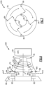
- the injectors 84 may be angled circumferentially relative to a tangent line 104 to induce a swirl component to the combined flow 90.
- Figure 3 illustrates injection of the intercooling water flow 88 at a circumferential angle 106 to the tangent line 104. Accordingly, the orientation of the injector 84 may be varied both relative to the flow axis 98 and the tangent line 104 to generate the desired direction of the combined flow 90 to the HPC inlet 78,
- the injector angle 100 may vary between 90 degrees and 25 degrees relative to the flow axis 98. In another disclosed example the injector angle may vary between about 30 and 90 degrees relative to the flow axis 98.
- the circumferential angle 106 may similarly vary between 0 and 90 degrees. It should be appreciated that although example angles are disclosed by way of example, other angles that generate a desired flow profile into the HPC inlet 78 may be utilized and are within the contemplation and scope of this disclosure.
- the example injectors 84 are schematically shown and may be of any configuration that provides the intercooling waterflow 88 into the passage 70. Moreover, the injectors 84 may provide proportional control of the volume of water injected or may be configured as fully on or fully off devices. Moreover, the disclosed system is shown schematically and would include a system of conduits, manifolds and valving required to supply and control the supply of pressurized intercooling water 56 to each of the injectors 84.
- an example intercooling system 125 embodiment is schematically shown and includes a plurality of injectors 84 mounted to a synchronization assembly schematically indicated at 82.
- the synchronization assembly 82 is coupled to an actuator 86 that is controlled by a controller 94.
- the controller 94 commands operation of the actuator 86 based on engine operating information to change a direction at which the intercooling water flow 56 is injected into the passage 70.
- the direction of injection of the intercooling water flow 88 is based on the incoming airflow 80 to provide a resultant direction of the combined air and water flow to the inlet 78.
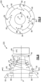
- the passage 70 is shown schematically in Figures 4 and 5 and illustrates the intercooling water flow 88 injected relative to the inlet airflow 80 to provide the resultant combined flow that is schematically indicated by arrows 90.
- the resultant flow 90 is in a direction desired for input into the HPC 64.
- the injectors 84 are arranged at circumferentially spaced intervals between an inner surface 72 and an outer surface of the passage 70. In the disclosed example, four groups of injection injectors 84 are shown, however, other numbers and groups of injectors 84 may be utilized and are within the scope and contemplation of this disclosure.
- the controller 94 may be programmed to operate each of the plurality of injectors 84 to vary a mass flow of water injected into the passage 70.
- the mass flow of water may be injected at varying amounts based on a position within the passage 70.
- the mass flow of water through each of the plurality of injectors 84 is individually varied to adjust and induce a desired swirl of the combined airflow and water flow into the HPC 64.
- the mass flow of water may be varied based on a circumferential position, a radial position or location to another structure.
- variations in the mass flow of water between the plurality of injectors 84 may be controlled and varied during an operational cycle of the propulsion system 20.
- a first sequence of water flow through each of the injectors 84 may be utilized during take-off conditions and changed once a cruise operating condition is entered.
- the mass flow of water may be varied based on real-time information indictive of engine operation.
- another example intercooling system embodiment 225 includes an injector configuration that is schematically shown and includes injectors 84 disposed at circumferential intervals on both the inner radial surface 72 and outer radial surface 74 of the passage 70.
- the injectors 84 may be operated individually or together to inject the intercooling waterflow 88 into the passage 70.
- the number and location of the injectors 84 may be varied to provide sufficient intercooling water flow 88 to both cool the compressed airflow 80 and to generate the flow direction desired in the common flow 90 that is communicated to the HPC 68.
- another example intercooling system 325 embodiment includes an injector configuration schematically shown that includes injectors 84 disposed about only the radially outer surface 74.
- the injectors 84 inject the intercooling water flow 88 relative to the incoming airflow 80 from the LPC 62.
- the resultant direction of the combined flow 90 provides the swirl and flow direction desired for introduction into the HPC 64.
- the direction at which the injectors 84 introduce the intercooling waterflow 88 varies based on engine operating conditions.
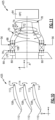
- another example intercooling system 425 embodiment includes an injector configuration that is schematically shown and includes injectors 114 mounted to exit guide vanes 108.
- the exit guide vanes 108 condition airflow from the LPC 62 and include a leading edge 110 and a trailing edge 112.
- At least one injector 114 is mounted proximate the trailing edge 112 of each of the exit guide vanes 108.
- the example exit guide vanes 108 are fixed and the injectors 84 are actuatable to alter a direction in which the intercooling water flow 88 is injected.
- each of the exit guide vanes 108 includes a plurality of injectors 114 spaced radially apart between the inner radial surface 72 and the outer radial surface 74 of the passage 70. Additionally, although each of the exit guide vanes 108 are disclosed by way of example as including at least one injector 114, not all of the exit guide vanes 108 need to have an injector 114.
- a direction and angle at which the injectors 84 direct water 88 into the passage 70 is varied to generate a defined swirl of a combined air and water flow as is schematically shown by arrows 90.
- the defined swirl provides the desired flow into the HPC 64 and increases resident time of water to maximize cooling evaporation.
Landscapes
- Engineering & Computer Science (AREA)
- Chemical & Material Sciences (AREA)
- Combustion & Propulsion (AREA)
- Mechanical Engineering (AREA)
- General Engineering & Computer Science (AREA)
- Structures Of Non-Positive Displacement Pumps (AREA)
Applications Claiming Priority (1)
| Application Number | Priority Date | Filing Date | Title |
|---|---|---|---|
| US18/512,388 US12215624B1 (en) | 2023-11-17 | 2023-11-17 | Fluidic compressor inlet guide vane |
Publications (2)
| Publication Number | Publication Date |
|---|---|
| EP4556700A2 true EP4556700A2 (fr) | 2025-05-21 |
| EP4556700A3 EP4556700A3 (fr) | 2025-08-13 |
Family
ID=93563519
Family Applications (1)
| Application Number | Title | Priority Date | Filing Date |
|---|---|---|---|
| EP24213340.3A Pending EP4556700A3 (fr) | 2023-11-17 | 2024-11-15 | Aube directrice d'entrée de compresseur fluidique |
Country Status (2)
| Country | Link |
|---|---|
| US (1) | US12215624B1 (fr) |
| EP (1) | EP4556700A3 (fr) |
Families Citing this family (1)
| Publication number | Priority date | Publication date | Assignee | Title |
|---|---|---|---|---|
| US12331687B1 (en) * | 2024-08-02 | 2025-06-17 | Rtx Corporation | Cryogenic fuel semi-closed injection cooled bottoming cycle |
Family Cites Families (14)
| Publication number | Priority date | Publication date | Assignee | Title |
|---|---|---|---|---|
| US2447696A (en) * | 1944-12-13 | 1948-08-24 | Fairey Aviat Co Ltd | Combustion gas and steam turbine arrangement |
| US2686631A (en) * | 1948-05-08 | 1954-08-17 | United Aircraft Corp | Coolant injection system for gas turbines |
| US3100964A (en) | 1959-11-25 | 1963-08-20 | Gen Motors Corp | Water injection system for a multistage compressor |
| US4569195A (en) | 1984-04-27 | 1986-02-11 | General Electric Company | Fluid injection gas turbine engine and method for operating |
| US6012279A (en) * | 1997-06-02 | 2000-01-11 | General Electric Company | Gas turbine engine with water injection |
| US6467252B1 (en) * | 1998-07-24 | 2002-10-22 | General Electric Company | Nozzles for water injection in a turbine engine |
| US6470667B1 (en) * | 1998-07-24 | 2002-10-29 | General Electric Company | Methods and apparatus for water injection in a turbine engine |
| GB2365074B (en) | 1999-07-13 | 2003-08-13 | Allison Advanced Dev Co | Gas turbine engine power boost using micro droplet liquid injection |
| US7272933B2 (en) * | 2004-01-28 | 2007-09-25 | General Electric Company | Methods and apparatus for operating gas turbine engines |
| US8291714B2 (en) * | 2007-12-06 | 2012-10-23 | Rolls-Royce Power Endgineering PLC | Radial staging method and configuration of a liquid injection system for power plants |
| DE102011107523B4 (de) | 2011-07-15 | 2016-08-11 | MTU Aero Engines AG | System zum Einblasen eines Fluids, Verdichter sowie Turbomaschine |
| US10677164B2 (en) * | 2016-11-15 | 2020-06-09 | General Electric Company | Cooling system for a turbine engine |
| FR3073002B1 (fr) | 2017-10-26 | 2020-11-06 | Safran Helicopter Engines | Aube de guidage avec circuit d'injection de liquide de refroidissement |
| US12163467B2 (en) * | 2022-05-13 | 2024-12-10 | Rtx Corporation | Condenser for hydrogen steam injected turbine engine |
-
2023
- 2023-11-17 US US18/512,388 patent/US12215624B1/en active Active
-
2024
- 2024-11-15 EP EP24213340.3A patent/EP4556700A3/fr active Pending
Also Published As
| Publication number | Publication date |
|---|---|
| US12215624B1 (en) | 2025-02-04 |
| EP4556700A3 (fr) | 2025-08-13 |
Similar Documents
| Publication | Publication Date | Title |
|---|---|---|
| EP4279722B1 (fr) | Séparateur d'eau à point de pincement de moteur à turbine alimenté en hydrogène | |
| US6550235B2 (en) | Combined cycle pulse detonation turbine engine operating method | |
| US7631484B2 (en) | High pressure ratio aft fan | |
| US11255544B2 (en) | Rotating detonation combustion and heat exchanger system | |
| US20130236296A1 (en) | Low Pressure Compressor Variable Vane Control for Two-Spool Turbofan or Turboprop Engine | |
| US20210140641A1 (en) | Method and system for rotating detonation combustion | |
| US20180356099A1 (en) | Bulk swirl rotating detonation propulsion system | |
| US11434831B2 (en) | Gas turbine combustor having a plurality of angled vanes circumferentially spaced within the combustor | |
| US12215634B1 (en) | Turbine engine including a steam system | |
| EP4556700A2 (fr) | Aube directrice d'entrée de compresseur fluidique | |
| US11702981B1 (en) | Turbine engine bleed waste heat recovery | |
| EP4556697A2 (fr) | Aubes directrices d'entrée de compresseur fluidique | |
| US12449126B2 (en) | Injecting fuel-steam mixture into turbine engine combustor | |
| US12031478B2 (en) | Air bottoming cycle driven propulsor | |
| US20190242582A1 (en) | Thermal Attenuation Structure For Detonation Combustion System | |
| EP4438868B1 (fr) | Moteur à turbine à gaz | |
| US20250059911A1 (en) | Turbine engine including a steam system | |
| US8851832B2 (en) | Engine and vane actuation system for turbine engine | |
| WO2024064270A1 (fr) | Propulseur entraîné par un cycle de fond d'air | |
| US12416260B2 (en) | Turbine engine including a steam system | |
| US20250163850A1 (en) | Turbine engine including a steam system | |
| US12320293B1 (en) | Turbine engine including a steam system | |
| EP4703643A1 (fr) | Buses de carburant à retour de déversement pour utilisation en tant que buses de démarrage | |
| EP4474629A1 (fr) | Conduit d'échappement refroidi par eau |
Legal Events
| Date | Code | Title | Description |
|---|---|---|---|
| PUAI | Public reference made under article 153(3) epc to a published international application that has entered the european phase |
Free format text: ORIGINAL CODE: 0009012 |
|
| STAA | Information on the status of an ep patent application or granted ep patent |
Free format text: STATUS: THE APPLICATION HAS BEEN PUBLISHED |
|
| AK | Designated contracting states |
Kind code of ref document: A2 Designated state(s): AL AT BE BG CH CY CZ DE DK EE ES FI FR GB GR HR HU IE IS IT LI LT LU LV MC ME MK MT NL NO PL PT RO RS SE SI SK SM TR |
|
| PUAL | Search report despatched |
Free format text: ORIGINAL CODE: 0009013 |
|
| AK | Designated contracting states |
Kind code of ref document: A3 Designated state(s): AL AT BE BG CH CY CZ DE DK EE ES FI FR GB GR HR HU IE IS IT LI LT LU LV MC ME MK MT NL NO PL PT RO RS SE SI SK SM TR |
|
| RIC1 | Information provided on ipc code assigned before grant |
Ipc: F02C 7/143 20060101AFI20250710BHEP Ipc: F02C 3/06 20060101ALI20250710BHEP |
|
| STAA | Information on the status of an ep patent application or granted ep patent |
Free format text: STATUS: REQUEST FOR EXAMINATION WAS MADE |
|
| 17P | Request for examination filed |
Effective date: 20260204 |