EP4556723A1 - Support de pistolet à clous et procédé - Google Patents
Support de pistolet à clous et procédé Download PDFInfo
- Publication number
- EP4556723A1 EP4556723A1 EP24213588.7A EP24213588A EP4556723A1 EP 4556723 A1 EP4556723 A1 EP 4556723A1 EP 24213588 A EP24213588 A EP 24213588A EP 4556723 A1 EP4556723 A1 EP 4556723A1
- Authority
- EP
- European Patent Office
- Prior art keywords
- bracket
- substrate
- nail gun
- interior volume
- base portion
- Prior art date
- Legal status (The legal status is an assumption and is not a legal conclusion. Google has not performed a legal analysis and makes no representation as to the accuracy of the status listed.)
- Withdrawn
Links
Images


Classifications
-
- F—MECHANICAL ENGINEERING; LIGHTING; HEATING; WEAPONS; BLASTING
- F16—ENGINEERING ELEMENTS AND UNITS; GENERAL MEASURES FOR PRODUCING AND MAINTAINING EFFECTIVE FUNCTIONING OF MACHINES OR INSTALLATIONS; THERMAL INSULATION IN GENERAL
- F16B—DEVICES FOR FASTENING OR SECURING CONSTRUCTIONAL ELEMENTS OR MACHINE PARTS TOGETHER, e.g. NAILS, BOLTS, CIRCLIPS, CLAMPS, CLIPS OR WEDGES; JOINTS OR JOINTING
- F16B2/00—Friction-grip releasable fastenings
- F16B2/20—Clips, i.e. with gripping action effected solely by the inherent resistance to deformation of the material of the fastening
- F16B2/22—Clips, i.e. with gripping action effected solely by the inherent resistance to deformation of the material of the fastening of resilient material, e.g. rubbery material
- F16B2/24—Clips, i.e. with gripping action effected solely by the inherent resistance to deformation of the material of the fastening of resilient material, e.g. rubbery material of metal
- F16B2/241—Clips, i.e. with gripping action effected solely by the inherent resistance to deformation of the material of the fastening of resilient material, e.g. rubbery material of metal of sheet metal
- F16B2/243—Clips, i.e. with gripping action effected solely by the inherent resistance to deformation of the material of the fastening of resilient material, e.g. rubbery material of metal of sheet metal internal, i.e. with spreading action
-
- B—PERFORMING OPERATIONS; TRANSPORTING
- B25—HAND TOOLS; PORTABLE POWER-DRIVEN TOOLS; MANIPULATORS
- B25C—HAND-HELD NAILING OR STAPLING TOOLS; MANUALLY OPERATED PORTABLE STAPLING TOOLS
- B25C1/00—Hand-held nailing tools; Nail feeding devices
- B25C1/08—Hand-held nailing tools; Nail feeding devices operated by combustion pressure
- B25C1/10—Hand-held nailing tools; Nail feeding devices operated by combustion pressure generated by detonation of a cartridge
- B25C1/18—Details and accessories, e.g. splinter guards, spall minimisers
- B25C1/188—Arrangements at the forward end of the barrel, e.g. splinter guards, spall minimisers, safety arrangements, silencers, bolt retainers
-
- F—MECHANICAL ENGINEERING; LIGHTING; HEATING; WEAPONS; BLASTING
- F16—ENGINEERING ELEMENTS AND UNITS; GENERAL MEASURES FOR PRODUCING AND MAINTAINING EFFECTIVE FUNCTIONING OF MACHINES OR INSTALLATIONS; THERMAL INSULATION IN GENERAL
- F16B—DEVICES FOR FASTENING OR SECURING CONSTRUCTIONAL ELEMENTS OR MACHINE PARTS TOGETHER, e.g. NAILS, BOLTS, CIRCLIPS, CLAMPS, CLIPS OR WEDGES; JOINTS OR JOINTING
- F16B5/00—Joining sheets or plates, e.g. panels, to one another or to strips or bars parallel to them
- F16B5/06—Joining sheets or plates, e.g. panels, to one another or to strips or bars parallel to them by means of clamps or clips
- F16B5/0685—Joining sheets or plates to strips or bars
-
- F—MECHANICAL ENGINEERING; LIGHTING; HEATING; WEAPONS; BLASTING
- F16—ENGINEERING ELEMENTS AND UNITS; GENERAL MEASURES FOR PRODUCING AND MAINTAINING EFFECTIVE FUNCTIONING OF MACHINES OR INSTALLATIONS; THERMAL INSULATION IN GENERAL
- F16B—DEVICES FOR FASTENING OR SECURING CONSTRUCTIONAL ELEMENTS OR MACHINE PARTS TOGETHER, e.g. NAILS, BOLTS, CIRCLIPS, CLAMPS, CLIPS OR WEDGES; JOINTS OR JOINTING
- F16B15/00—Nails; Staples
-
- H—ELECTRICITY
- H02—GENERATION; CONVERSION OR DISTRIBUTION OF ELECTRIC POWER
- H02G—INSTALLATION OF ELECTRIC CABLES OR LINES, OR OF COMBINED OPTICAL AND ELECTRIC CABLES OR LINES
- H02G3/00—Installations of electric cables or lines or protective tubing therefor in or on buildings, equivalent structures or vehicles
- H02G3/26—Installations of cables, lines, or separate protective tubing therefor directly on or in walls, ceilings, or floors
- H02G3/263—Installation, e.g. suspension, of conduit channels or other supports
Definitions
- raceways including conduit, such as electric metallic tube (EMT) conduit, or cable, such as metal clad (MC) cable, relative to a substrate such as concrete.
- EMT electric metallic tube
- MC metal clad
- support of the raceways and cables must be provided at least at or within specified distances along a support structure and within specified distances from a junction box or other termination point as required by code. It may also be useful to fixedly support other objects relative to substrates, including threaded rods, support lines (e.g., wires or metal cables), and so on.
- Some examples of the disclosed technology can provide improved nail gun brackets and related methods.
- some implementations can provide a bracket with a contact portion that is configured to seat against a substrate and a recessed portion that is offset away from the contact portion.
- Such arrangements can provide beneficial deformation of a bracket during installation, including as can provide improved alignment and overall security.
- a nail gun bracket for supporting an object relative to a substrate of concrete or other material.
- a base portion can be hingedly connected to a base portion, to be movable between an open configuration, to receive an object into an interior volume of the bracket, and a closed configuration, to retain the object within the interior volume.
- the base portion can include an object side that faces toward the interior volume and a substrate side opposite the object side and configured to face toward the substrate in an installed configuration.
- the substrate side can define a contact portion and a recessed portion.
- the contact portion can define a contact plane along the substrate for an installed configuration of the nail gun bracket.
- the recessed portion can be offset from the contact plane toward the interior volume.
- the recessed portion can include a support boss that receives a nail gun nail to secure the base portion to the substrate.
- the support boss can one or more of: protruding outwardly away from the interior volume to a support-boss distal surface that is offset from the contact plane toward the interior volume; or extending in an elongate direction along the base portion between, and being offset toward the interior volume from, a first contact pad and a second contact pad.
- the first and second contact pads can be configured to seat on the substrate in the installed configuration.
- the first and second contact pads can extend along the contact plane.
- the support boss can include a first hole to receive the nail gun nail through the base portion and into the substrate.
- the support boss further can include a keyhole cutout, spaced apart from the first hole.
- the contact portion can further include rails spaced from opposed lateral sides of the support boss and extending along the contact plane.
- the rails can be configured to seat on the substrate in the installed configuration (e.g., can be planar rails).
- the rails can be separated from the support boss by recessed channels having a greater offset from the contact plane toward the interior volume than does the support boss.
- the recessed channels can extend along an entire elongate length of the contact portion.
- the gate portion can include a protrusion that extends away from the interior volume.
- the gate portion can be movable from the open configuration to the closed configuration by applying a closing force to the protrusion at an opposite side of protrusion from the base portion.
- the base portion can include a protruding tab and the gate portion can include an aperture with an upper edge.
- the protruding tab can be received into the aperture to be retained by the upper edge as the gate portion is moved to the closed configuration.
- the protruding tab can angle toward the contact plane.
- the gate portion can include an access opening aligned with the support boss to receive a nail gun barrel through the access opening to install the nail gun nail through the support boss.
- a method for supporting an object relative to a substrate of concrete or other material.
- a nail gun bracket e.g., as variously detailed above
- a nail gun bracket can be secured to a substrate by firing a nail from within an interior volume of the bracket, through a support boss, to deform the support boss toward the substrate.
- the nail gun can be removed from the bracket.
- the gate portion With the gate portion in an open configuration, an object can be inserted past a gate portion into an interior volume of the bracket. The object can be secured within the interior volume by moving the gate portion toward the base portion, from the open configuration to a closed configuration.
- securing the nail gun bracket can include extending a barrel of the nail gun through an access opening in the gate portion of the bracket.
- moving the gate portion toward the base portion can include engaging a protrusion of the gate portion that extends away from the interior volume to move the base portion toward the substrate.
- the support boss can be deformed to contact the substrate.
- the nail gun bracket can include a base portion, and a gate portion hingedly connected to the base portion.
- the gate portion can be movable between an open configuration, to receive an object into an interior volume of the bracket, and a closed configuration, to retain the object within the interior volume.
- the gate portion can include a protrusion that extends away from the interior volume, and can be movable from the open configuration to the closed configuration by engagement of the protrusion at an opposite side of protrusion from the base portion.
- the base portion can include a contact portion that defines a contact plane along the substrate, and a non-contact portion recessed from the contact plane.
- the base portion can include a first hole to receive a nail through the base portion into the substrate.
- the base portion can include a keyhole cutout, spaced apart from the first hole.
- the gate portion can include a cutout.
- the protrusion can be an integrally formed tab.
- the protrusion can include a bend that orients a free end of the protrusion away from the base portion.
- the base portion can include a contact portion that defines a contact plane along the substrate and a first tab that angles toward the contact plane.
- the gate portion can include an opening that receives the first tab to lock the gate portion in the closed configuration.
- Some examples of the disclosed technology provide a method for supporting an object relative to a substrate of concrete or other material.
- a barrel of a nail gun can be extended through a first hole in a gate portion of a bracket. With the barrel through the first hole, the bracket can be secured to the substrate with a nail through a second hole in a base portion of the bracket.
- the nail gun can be removed from the bracket and, with the gate portion in an open orientation, the object can be inserted past a gate portion into an interior volume of the bracket.
- the object can be secured within the interior volume by engaging a protrusion of the gate portion that extends away from the interior volume to move the gate portion toward the base portion, from the open configuration to a closed configuration.
- brackets that can be used to support a conduit or a cable relative to a structure.
- the context and particulars of this discussion are presented as examples only.
- different implementations of the disclosed technology can be configured in various ways, including with other shapes and arrangements of elements.
- examples of the disclosed technology can be used in various arrangements, including with substrates or various other assemblies that may differ from those expressly illustrated or described herein.
- some examples not expressly discussed below can include some or all of the components of any number of the examples expressly described and illustrated below, in any variety of combinations.
- some examples can be employed to support objects other than conduit or cables, including hanging (e.g., threaded) rods, or other support brackets, and some examples may be installed with tools other than nail guns or fasteners other than nails.
- conduit, cable, or other objects can be secured to structures, including concrete structures, in various ways.
- a bracket can be attached to concrete using a nail gun to drive a nail through the bracket and into a concrete substrate. Conduit or cable (or other objects) can then be supported, directly or indirectly, by the bracket.
- installation can require inconvenient operations to hold the bracket in place against the concrete (e.g., far above the head of an operator), misfires of nail guns can render parts unusable, and manipulation of brackets after installation may be relatively difficult (e.g., because far above the head of an operator).
- some conventional designs configured to seat against a support substrate when installed may exhibit unfavorable deformation patterns during installed, which may lead to generally misaligned or reduced-strength installations.
- brackets can include gate portions that are movable relative to base portions (e.g., via integral attachment by a living hinge).
- objects e.g., cables
- the gate portion can then be moved to a closed configuration, to secure the objects within the interior volume and thus ensure that the objects are supported relative to the substrate.
- a protrusion can extend from the gate portion to the outside of the interior volume, to provide an engagement structure for application of force from opposite the substrate (e.g., from the ground, for a ceiling installation).
- an operator can use a pole or other reach-extender to easily apply a closing force to the gate portion, even for relatively high (or otherwise distant) installations.
- some examples can include protrusions with downwardly extending free ends, to more readily engage with the end of any particular pole or other body that an operator may be using.
- brackets according to the disclosure can include improved latching structures for easier and more secure engagement between gate portions and corresponding base portions (e.g., to latch a bracket in a closed configuration around cable or conduit).
- brackets according to the disclosure can include additional openings to facilitate easier use with nail guns, or can include base portions with recessed structures to provide improved engagement with the corresponding substrates.
- brackets can include a base portion that is configured to be installed against concrete or other substrates, and the base portion can include a combination of contact portions (e.g., that seat against the substrate) and recessed portion (e.g., that are offset away from the contact portions, in a direction away from the substrate).
- a recessed portion of a bracket can include a support structure for a fastener that protrudes away from an interior volume of the bracket or that is recessed from a contact plane (at the substrate) defined by other portions of the nail gun bracket.
- a support boss structure can protrude away from an interior volume of a bracket and can be offset away from a relevant contact plane.
- offset structure(s) alone and particularly in combination, can provide for improved behavior of a nail gun bracket during installation, including with intentional deformation to provide improved hold in some cases, and with improved structures for initially establishing and then maintaining alignment of a nail gun barrel (or other tool).
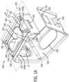
- FIGS. 1-5 illustrate an example bracket 100 according to an example of the present disclosure, with the bracket 100 in an open (e.g., pre-installation) configuration.
- the bracket 100 includes a base portion 105 configured to extend along (e.g., seat on) a substrate in an installed configuration, a gate portion 110 that is connected to the base portion 105 by a hinge 135.
- the bracket 100 in the open (e.g., pre-installation) configuration can receive cables or other objects past the gate portion 110 into an interior volume 102 of the bracket 100.
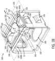
- the gate portion 110 can then be hingedly moved relative to the base portion 105 to a closed configuration (see FIG. 1B ) to secure the objects within the interior volume 102.
- the base portion 105 is generally configured to extend along the relevant substrate (e.g., concrete) and further defines a combination of protruding and recessed geometry for improved engagement with the substrate.
- the base portion 105 can include a contact portion 115 configured to seat against the relevant substrate (e.g., concrete).
- the base portion 105 in some examples can beneficially include various recessed structures, relative to the contact portion 115, that are configured to be recessed from a substrate during (and, e.g., also after) installation. Such arrangements, for example, can provide for a more resilient engagement between the bracket and the substrate, to complement the retention force of a corresponding fastener (e.g., nail-gun nail).
- a corresponding fastener e.g., nail-gun nail
- the base portion 105 is generally L-shaped, with a support portion configured to extend along the substrate and a leg that extends (relatively rigidly) from the support portion to the hinge 135.
- a length of the base portion 105 that is configured to extend along the substrate can define a substrate side 105A that faces toward the substrate as installed, and an object side 105B that faces toward the interior volume 102.
- the substrate side 105A in particular can define contours with greater or lesser offset relative to the substrate, as installed, or relative to a reference plane corresponding thereto.
- different offsets may be defined relative to a reference plane defined by structures of the bracket 100 itself (e.g., structures configured to seat on the substrate, as further detailed in examples below).
- recessed geometry can extend around (e.g., surround) an opening to receive a nail-gun nail or other fastener.
- a tiered, recessed geometry can be provided. For example, different structures offset from a reference plane by different distances, to provide favorable characteristics in resilient response during installation and overall installation strength.
- a contact portion can define contact pads at select locations along a base portion (e.g., for seated engagement with the substrate).
- discrete contact pads can be provided at opposed elongate ends of a recessed portion of a base portion of a bracket, to provide an improved resilient response of the material of the bracket therebetween during (and after) installation.
- contact pads can be provided at opposed ends of a support boss configured to receive a fastener for installation.
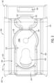
- the contact portion 115 defines a contact plane 120 (see FIGS. 1 and 2 ) along which the contact portion 115 - and the base portion 105 generally - can seat against a substrate (e.g., a concrete ceiling).
- the contact plane 120 can be defined by lateral side rails 122 (e.g., planar rails, as shown) and end contact pads 132, 134, as shown.
- lateral side rails 122 e.g., planar rails, as shown
- end contact pads 132, 134 as shown.
- a contact portion In different examples, various configurations of a contact portion are possible. For example, different structures than the planar rails 122 may be provided along the edges of the contact portion 115 or otherwise spaced to either lateral direction L1, L2 from a fastener opening of the bracket 100 (e.g., a hole 140, as further discussed below). Similarly, in different examples, a reference contact plane may be defined by continuous or discontinuous regions of a base portion. For example, as shown, lateral recessed portions 130 are formed as channels extending a full elongate length of the base portion 105 and the recessed portions 130 correspondingly separate the pads 132, 134 from the rails relative to the lateral directions L1, L2.
- a central recessed portion 125 can separate the pads 132, 134 from each other along an elongate direction, perpendicular to the lateral directions L1, L2.
- the recessed portion 125 can include a support boss 128 for fasteners that protrudes away from the interior volume 102 toward the contact plane 120 - e.g., with a different offset of a support-boss distal (e.g., top, outer) surface 128A from the contact plane 120 than of the recessed portions 130 from the contact plane 120.
- contact pads, rails or other structures of a base portion can extend continuously across an elongate length or lateral width of a bracket with a common height to continuously define a contact (or other) plane.
- planar surfaces e.g., the rails 122
- planar distal surfaces of the pads 132, 134 can provide similar benefits.
- configuration of recessed and contact portions along a base portion for a bracket can allow a bracket to be beneficially deformed by a fastener during the installation of the fastener to secure the bracket to a substrate.
- the support-boss distal surface 128A is offset away from the support plane 120.
- installation of a nail 108 (see FIG. 2 ) or other fastener through the fastener hole 140 can result in the deformation of bracket 100 to move the support boss 128 upward toward the support plane 120 and the corresponding substrate (e.g., to reduce the offset or even seat part of the support boss 128 onto the substrate).
- inclusion of the recessed portion 125, offset from the support plane 120 may result in a localized deformation of the bracket 100 toward the substrate upon installation of fastener, to induce a corresponding resilient response from the bracket 100 that enhances the hold of the nail.
- a beneficial profile for such a deformation - and the resultant installed configuration - can be provided in particular by inclusion of the distinct and distinctly offset recessed portions 125, 130 in combination. In some examples, however, only one of the types of recessed portions 125, 130 may be included.
- the support boss 128 extends in an elongate direction along the base portion 105 between the first contact pad 132 and the second contact pad 134, bounded on lateral sides (i.e., in the lateral directions L1, L2) by the channels 130. Further, while the support boss 128 and the channels 130 are offset from the contact plane 120 toward the interior volume 102, the channels 130 have a greater offset from the contact plane 120 than does the support boss 128. Moreover, the channels 130 in particular extend along an entire elongate length of the contact portion 105, and thus also separate the contact pads 132, 134 from the rails 122.
- Such an arrangement may in some cases provide particularly beneficial resilient engagement of the bracket 100 with a substrate.
- the contact pads 132, 134 on opposing sides of the hole 140 - and the offset recessed portion 125, generally - may allow for stable and easy alignment on a substrate during staging for installation, along with a deformation mode with laterally centralized and longitudinally distributed deformation of the support boss. Further, different modes of deformation can be induced via the channels 130 and via the offset between the contact pads 132, 134 and the support boss 128, with corresponding improvements in overall engagement.
- the contact portion 115 of the base portion 105 further includes the hole 140 that can receive a nail to secure the bracket 100 against a substrate.
- the hole 140 is centered in a (partly) circular portion of the recessed portion 125, corresponding to the protrusion (and offset) of the support boss 128 away from the interior volume 102.
- a barrel 106 of a nail gun can be nested relatively securely into the circular portion to help ensure appropriate alignment with the hole 140 and help secure the bracket 100 in a staged configuration on the nail gun.
- firing of a nail through the hole 140 can result in beneficial local deformation of the bracket 100 relative to the corresponding substrate.
- a pre-formed hole may not be included, without loss of other benefits discussed herein (e.g., beneficial deformation of the recessed portion 125 during installation).
- the bracket 100 can include a keyhole cutout 160.
- the cutout 160 is located on the recessed portion 125 (and the support boss 128), spaced in the length direction apart from the hole 140 and the corresponding circular portion of the recessed portion 125.
- the bracket 100 can also be easily and securely connected to substrate using a pre-installed fastener.
- additional keyhole cutouts or other mounting openings can be provided (e.g., on a back wall of the base portion 105, as shown).
- the gate portion 110 has a first protrusion 145 formed as an integral tab that extends to the outside of (and away from) the interior volume 102.
- the first protrusion 145 is thus arranged to receive an external force to push the gate portion 110 towards the base portion 105 and thereby hingedly move the gate portion 110 to a closed configuration.
- an operator may extend a pole or other object from the ground to engage with the protrusion 145 and thus easily urge the bracket 100 into a closed configuration, even for relatively high installations.
- the protrusion 145 can exhibit different geometries.
- a free end of the protrusion 145 can be oriented to extend away from the base portion 105 (e.g., toward the ground, for a ceiling installation).
- the protrusion 145 can include a bend that helps both to space a free end of the protrusion 145 away from the body of the gate portion 110 and to orient the free end for easy engagement by an operator (e.g., from a distantly spaced floor of the relevant building).
- a latching mechanism can be provided on the gate portion 110 and the base portion 105.
- the external force on the first protrusion 145 can also help to engage a latching mechanism to secure the gate portion 110 in the closed configuration.
- a latching mechanism can include a second aperture 150 on the gate portion 110.
- a top edge of the aperture 150 can include a corresponding protrusion.
- a protrusion can extend inwardly relative to the interior volume 102, and may be integrally formed on the gate portion 110 as a louver, another offset structure or otherwise.
- the base portion can have a third protrusion formed as a tab 155 that extends outwardly relative to the interior volume 102 (e.g., also formed as an integral tab).
- the top edge of the aperture 150 (or other latch feature) and the third protrusion 155 (or other latch feature) can thus be matingly engaged by the closing of the bracket 100 (e.g., via remote manual engagement with the protrusion 145), to secure the gate portion 110 in the closed configuration - e.g., with the upward angle of the protrusion 155 securely retaining a corresponding upward angle at a top edge of the aperture 150, as shown in FIG. 1B , in particular).
- engagement of the protrusion 145 by an operator can in particular urge the aperture 150 of the gate portion 110 and the third protrusion 155 of the base portion 105 towards each other.
- inclusion of the protrusion 155 on the base portion 105 and the aperture 150 on the gate portion 110 may provide a favorable alignment of forces during operations to close the bracket 100, particularly with angled profiles as shown and described.
- the base portion 105 and gate portion 110 are integrally formed as part of a single component (e.g., formed from mild steel, spring steel, or other material). This configuration may provide particularly strong and usable brackets. Integral formation can also reduce the number of parts that a use is required to manage during installation. In other examples, however, other configurations are possible.
- the bracket 100 is configured to be moved between an open (e.g., pre-installation) configuration and a closed (e.g., support) configuration.
- a bracket can be configured to be manually moved from an open installation configuration to a closed support configuration (or vice versa, in some cases).
- an operator may manually (e.g., using a pipe or other reach-extender) press the first protrusion 145 to urge the gate portion 110 towards the base portion 105.
- the gate portion 110 can be easily latched in a closed configuration (e.g., by engaging the top edge of the aperture 150 and the third protrusion 155, to fully enclose a perimeter of the interior volume 102 of the bracket 100.
- the recessed portion 125 of the base portion 105 of the bracket 100 can be pressed toward the substrate (e.g., upwardly from the perspective of FIG. 2 ).
- the corresponding flexion of the recessed portion 125 can help to create a tighter securement of the bracket 100 against the substrate.
- a hole can be provided in a gate portion to allow for easier alignment of a nail gun barrel or other fastening tool during installation.
- the nail gun barrel 106 may be inserted through a second hole 165 of the gate portion 110 (see, e.g., FIG. 2 ).
- the second hole 165 of the gate portion 110 provides clearance for insertion of a nail gun barrel for attachment of the bracket 100 to a substrate.
- the barrel may be axially aligned with the first hole 140 (and the corresponding area of the recessed portion 125) to fire a nail 108 to secure the bracket 100 against a substrate.
- the hole 165 can accordingly help to guide the barrel 106 towards the hole 140 of the base portion 105 (see also FIG. 1A ) and the corresponding part of the recessed portion 125 (e.g., where the barrel 106 can be nested to magnetically or otherwise engage the bracket 100).
- devices or systems disclosed herein can be utilized, manufactured, installed, etc. using methods embodying aspects of the disclosed technology.
- any description herein of particular features, capabilities, or intended purposes of a device or system should be considered to disclose, as examples of the disclosed technology a method of using such devices for the intended purposes, a method of otherwise implementing such capabilities, a method of manufacturing relevant components of such a device or system (or the device or system as a whole), and a method of installing disclosed (or otherwise known) components to support such purposes or capabilities.
- discussion herein of any method of manufacturing or using for a particular device or system, including installing the device or system should be understood to disclose, as examples of the disclosed technology, the utilized features and implemented capabilities of such device or system.
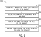
- some implementations of the disclosed technology provide an example method 1000 for securing an object to a substrate of concrete.
- operations of the method in particular are discussed relative to the bracket 100, other brackets according to the disclosed principles can also be similarly employed. Further, some of the illustrated operations can be executed differently, or not at all, in some implementations.
- the method includes inserting 1010 a barrel of a nail gun through a relevant hole (e.g., the second hole 165) to temporarily secure the bracket to the nail gun and correspondingly align the barrel with a base portion of the bracket (e.g., align the barrel with the hole 165 of the recessed portion 125 of the bracket 100).
- a relevant hole e.g., the second hole 165
- the bracket can then be secured 1020 to the substrate with the nail gun.
- the nail gun can be operated to fire a nail through a pre-formed (or other) hole on the bracket 100 (e.g., the hole 140).
- this fastening operation can in some cases intentionally cause a deformation of a base portion of the bracket (e.g., as detailed for the base portion 105, above).
- the nail gun can then be removed 1030 from the bracket, e.g., by being axially withdrawn from the second hole 165, and then used for further operations.
- a protrusion on a gate portion of the bracket can be engaged 1040 to move the bracket to a closed configuration.
- a pipe or other rigid body can be used by an operator standing on the ground to engage the protrusion 145 of the bracket 100 and thereby hingedly move the gate portion 110 to the closed configuration.
- the same force from an operator can cause a latching engagement of the gate portion 110 and the base portion 105 (e.g., the edge of the aperture 150 and third protrusion 155 may be interlocked or otherwise engaged 1040, to secure the bracket in a closed configuration).
- a bracket 200 can be provided as an alternative configuration of the bracket 100.
- the bracket 200 is similar to the bracket 100, and discussion of the bracket 100 above thus also applies to the bracket 200.
- the bracket 200 is different.
- the bracket 200 exhibits a larger length along a top and bottom side and a correspondingly larger aspect ratio of length over width.
- the bracket 200 also exhibits a relatively long recessed portion 225, which is generally similar to the recessed portion 125 but extends over the entire length of the top (as shown) side of the bracket 200. Either or both of these different aspects can, in some examples, be combined together with other aspects of the configuration of the bracket 100, as discussed above.
- the brackets 100, 200 as shown exhibit particularly beneficial latching arrangements, relative to the ease of operation for an operator (e.g., via the protrusion 145, from far below) and relative to the secureness of the closure.
- other configurations are possible, including as variously illustrated in FIGS. 8 and 9 .
- FIG. 8 in particular, various geometries for a latch tab 155A through 155E are possible, and reinforcing embosses, gussets or other features can be included in some cases for improved strength or other performance.
- a latch feature of a gate portion can be variously configured as a hook tab E1, as a louvre E2, or as an offset E3, as well as in a variety of other ways.
- examples of the disclosed technology can provide an improved bracket for securing objects (e.g., conduit or cables) to a substrate of concrete or other materials.
- brackets according to the disclosed technology can substantially reduce the time and labor that may be required during installation and use, such as by obviating the need to hold the bracket with one hand and operate a nail gun with the other to secure the bracket to the substrate.
- some examples of the disclosed technology can be releasably engaged with the barrel of the nail gun before positioning the bracket in place, thereby allowing for attachment of the bracket to a substrate in hard or difficult areas to reach, including instances in which a nail gun is attached to an extension pole to secure a bracket high overhead.
- some examples of the disclosed technology can be used, without modification, on a variety of nail guns having respective barrels with a variety of sizes.
- a list preceded by "one or more” (and variations thereon) and including “or” to separate listed elements indicates options of one or more of any or all of the listed elements.
- the phrases “one or more of A, B, or C" and “at least one of A, B, or C” indicate options of: one or more A; one or more B; one or more C; one or more A and one or more B; one or more B and one or more C; one or more A and one or more C; and one or more A, one or more B, and one or more C.
- a list preceded by "a plurality of' (and variations thereon) and including “or” to separate listed elements indicates options of one or more of each of multiple of the listed elements.
- phrases "a plurality of A, B, or C" and “two or more of A, B, or C” indicate options of: one or more A and one or more B; one or more B and one or more C; one or more A and one or more C; and one or more A, one or more B, and one or more C.
- integral and derivatives thereof (e.g., “integrally") describe elements that are manufactured as a single piece without fasteners, adhesive, or the like to secure separate components together.
- an element that is stamped, cast, or otherwise molded as a single-piece component from a single piece of sheet metal or other continuous single piece of material, without rivets, screws, other fasteners, or adhesive to hold separately formed pieces together is an integral (and integrally formed) element.
- an element formed from multiple pieces that are separately formed initially then later connected together is not an integral (or integrally formed) element.
- ordinal numbers are used herein for convenience of reference, based generally on the order in which particular components are presented in the relevant part of the disclosure.
- designations such as “first,” “second,” etc. generally indicate only the order in which a thus-labeled component is introduced for discussion and generally do not indicate or require a particular spatial, functional, temporal, or structural primacy or order.
- similar or identical components may be referred to with different ordinal numbers in different contexts.
Landscapes
- Engineering & Computer Science (AREA)
- General Engineering & Computer Science (AREA)
- Mechanical Engineering (AREA)
- Chemical & Material Sciences (AREA)
- Combustion & Propulsion (AREA)
- Connection Of Plates (AREA)
Applications Claiming Priority (1)
| Application Number | Priority Date | Filing Date | Title |
|---|---|---|---|
| US202363600592P | 2023-11-17 | 2023-11-17 |
Publications (1)
| Publication Number | Publication Date |
|---|---|
| EP4556723A1 true EP4556723A1 (fr) | 2025-05-21 |
Family
ID=93566622
Family Applications (1)
| Application Number | Title | Priority Date | Filing Date |
|---|---|---|---|
| EP24213588.7A Withdrawn EP4556723A1 (fr) | 2023-11-17 | 2024-11-18 | Support de pistolet à clous et procédé |
Country Status (1)
| Country | Link |
|---|---|
| EP (1) | EP4556723A1 (fr) |
Citations (1)
| Publication number | Priority date | Publication date | Assignee | Title |
|---|---|---|---|---|
| CN108266570B (zh) * | 2016-12-30 | 2020-04-07 | 喜利得股份公司 | 保持器 |
-
2024
- 2024-11-18 EP EP24213588.7A patent/EP4556723A1/fr not_active Withdrawn
Patent Citations (1)
| Publication number | Priority date | Publication date | Assignee | Title |
|---|---|---|---|---|
| CN108266570B (zh) * | 2016-12-30 | 2020-04-07 | 喜利得股份公司 | 保持器 |
Similar Documents
| Publication | Publication Date | Title |
|---|---|---|
| EP2045512B1 (fr) | Support de composants pour fixation sur un panneau | |
| JP3359021B2 (ja) | バー・ハンガーおよび取付クリップ組立体 | |
| US4408262A (en) | Plaster frame for recessed lighting | |
| EP3771853A1 (fr) | Pince de support | |
| US12294208B2 (en) | Support system for electrical boxes | |
| US12049758B1 (en) | Apparatus and method for hanging architectural panels with concealed attachment points | |
| US7714227B2 (en) | Cable junction box configured to store one or more coils of cable | |
| US7603814B1 (en) | Decking system hanger | |
| CA2551509C (fr) | Rallonge coulissante de boite electrique | |
| US11355906B2 (en) | Attachment for an electrical box | |
| CN109425089B (zh) | 风口安装结构、室内机及空调机组 | |
| EP4556723A1 (fr) | Support de pistolet à clous et procédé | |
| US9054510B2 (en) | Utility meter socket and conduit and method of installation | |
| US20140109484A1 (en) | Access panel with spring-loaded plastic support arms | |
| EP1898016B1 (fr) | Faux plafond avec des panneaux pivotables par dessous | |
| US10508767B2 (en) | Systems and methods for mounting electrical device to junction box | |
| CN212914933U (zh) | 夹持系统和夹持组件 | |
| JP6940440B2 (ja) | 管状体固定具及びその構造 | |
| CN213755222U (zh) | 一种机柜空调及其机柜 | |
| EP3730825A1 (fr) | Systèmes et procédés de support pour un pistolet cloueur | |
| US20210362310A1 (en) | Systems and Methods for Installing a Panel of an Enclosure | |
| JP6940439B2 (ja) | 基材と取付体との組付け維持構造 | |
| US20250369578A1 (en) | Bracket system for lighting assemblies | |
| KR100421995B1 (ko) | 카메라용 아답터 조립체 | |
| JPH0612452Y2 (ja) | 空気調和機 |
Legal Events
| Date | Code | Title | Description |
|---|---|---|---|
| PUAI | Public reference made under article 153(3) epc to a published international application that has entered the european phase |
Free format text: ORIGINAL CODE: 0009012 |
|
| STAA | Information on the status of an ep patent application or granted ep patent |
Free format text: STATUS: THE APPLICATION HAS BEEN PUBLISHED |
|
| AK | Designated contracting states |
Kind code of ref document: A1 Designated state(s): AL AT BE BG CH CY CZ DE DK EE ES FI FR GB GR HR HU IE IS IT LI LT LU LV MC ME MK MT NL NO PL PT RO RS SE SI SK SM TR |
|
| STAA | Information on the status of an ep patent application or granted ep patent |
Free format text: STATUS: THE APPLICATION IS DEEMED TO BE WITHDRAWN |
|
| 18D | Application deemed to be withdrawn |
Effective date: 20251122 |