EP4556747A1 - Transmission et dispositif de transmission d'entraînement de véhicule équipé de celle-ci - Google Patents
Transmission et dispositif de transmission d'entraînement de véhicule équipé de celle-ci Download PDFInfo
- Publication number
- EP4556747A1 EP4556747A1 EP23871387.9A EP23871387A EP4556747A1 EP 4556747 A1 EP4556747 A1 EP 4556747A1 EP 23871387 A EP23871387 A EP 23871387A EP 4556747 A1 EP4556747 A1 EP 4556747A1
- Authority
- EP
- European Patent Office
- Prior art keywords
- gear
- transmission
- fixing
- friction
- axis
- Prior art date
- Legal status (The legal status is an assumption and is not a legal conclusion. Google has not performed a legal analysis and makes no representation as to the accuracy of the status listed.)
- Pending
Links
Images




Classifications
-
- F—MECHANICAL ENGINEERING; LIGHTING; HEATING; WEAPONS; BLASTING
- F16—ENGINEERING ELEMENTS AND UNITS; GENERAL MEASURES FOR PRODUCING AND MAINTAINING EFFECTIVE FUNCTIONING OF MACHINES OR INSTALLATIONS; THERMAL INSULATION IN GENERAL
- F16H—GEARING
- F16H48/00—Differential gearings
- F16H48/06—Differential gearings with gears having orbital motion
- F16H48/10—Differential gearings with gears having orbital motion with orbital spur gears
- F16H48/11—Differential gearings with gears having orbital motion with orbital spur gears having intermeshing planet gears
-
- B—PERFORMING OPERATIONS; TRANSPORTING
- B60—VEHICLES IN GENERAL
- B60K—ARRANGEMENT OR MOUNTING OF PROPULSION UNITS OR OF TRANSMISSIONS IN VEHICLES; ARRANGEMENT OR MOUNTING OF PLURAL DIVERSE PRIME-MOVERS IN VEHICLES; AUXILIARY DRIVES FOR VEHICLES; INSTRUMENTATION OR DASHBOARDS FOR VEHICLES; ARRANGEMENTS IN CONNECTION WITH COOLING, AIR INTAKE, GAS EXHAUST OR FUEL SUPPLY OF PROPULSION UNITS IN VEHICLES
- B60K1/00—Arrangement or mounting of electrical propulsion units
-
- F—MECHANICAL ENGINEERING; LIGHTING; HEATING; WEAPONS; BLASTING
- F16—ENGINEERING ELEMENTS AND UNITS; GENERAL MEASURES FOR PRODUCING AND MAINTAINING EFFECTIVE FUNCTIONING OF MACHINES OR INSTALLATIONS; THERMAL INSULATION IN GENERAL
- F16H—GEARING
- F16H3/00—Toothed gearings for conveying rotary motion with variable gear ratio or for reversing rotary motion
- F16H3/44—Toothed gearings for conveying rotary motion with variable gear ratio or for reversing rotary motion using gears having orbital motion
- F16H3/62—Gearings having three or more central gears
- F16H3/66—Gearings having three or more central gears composed of a number of gear trains without drive passing from one train to another
-
- F—MECHANICAL ENGINEERING; LIGHTING; HEATING; WEAPONS; BLASTING
- F16—ENGINEERING ELEMENTS AND UNITS; GENERAL MEASURES FOR PRODUCING AND MAINTAINING EFFECTIVE FUNCTIONING OF MACHINES OR INSTALLATIONS; THERMAL INSULATION IN GENERAL
- F16H—GEARING
- F16H61/00—Control functions within control units of change-speed- or reversing-gearings for conveying rotary motion ; Control of exclusively fluid gearing, friction gearing, gearings with endless flexible members or other particular types of gearing
- F16H61/26—Generation or transmission of movements for final actuating mechanisms
- F16H61/28—Generation or transmission of movements for final actuating mechanisms with at least one movement of the final actuating mechanism being caused by a non-mechanical force, e.g. power-assisted
- F16H61/32—Electric motors , actuators or related electrical control means therefor
-
- B—PERFORMING OPERATIONS; TRANSPORTING
- B60—VEHICLES IN GENERAL
- B60K—ARRANGEMENT OR MOUNTING OF PROPULSION UNITS OR OF TRANSMISSIONS IN VEHICLES; ARRANGEMENT OR MOUNTING OF PLURAL DIVERSE PRIME-MOVERS IN VEHICLES; AUXILIARY DRIVES FOR VEHICLES; INSTRUMENTATION OR DASHBOARDS FOR VEHICLES; ARRANGEMENTS IN CONNECTION WITH COOLING, AIR INTAKE, GAS EXHAUST OR FUEL SUPPLY OF PROPULSION UNITS IN VEHICLES
- B60K1/00—Arrangement or mounting of electrical propulsion units
- B60K2001/001—Arrangement or mounting of electrical propulsion units one motor mounted on a propulsion axle for rotating right and left wheels of this axle
-
- B—PERFORMING OPERATIONS; TRANSPORTING
- B60—VEHICLES IN GENERAL
- B60Y—INDEXING SCHEME RELATING TO ASPECTS CROSS-CUTTING VEHICLE TECHNOLOGY
- B60Y2200/00—Type of vehicle
- B60Y2200/90—Vehicles comprising electric prime movers
- B60Y2200/91—Electric vehicles
-
- F—MECHANICAL ENGINEERING; LIGHTING; HEATING; WEAPONS; BLASTING
- F16—ENGINEERING ELEMENTS AND UNITS; GENERAL MEASURES FOR PRODUCING AND MAINTAINING EFFECTIVE FUNCTIONING OF MACHINES OR INSTALLATIONS; THERMAL INSULATION IN GENERAL
- F16H—GEARING
- F16H61/00—Control functions within control units of change-speed- or reversing-gearings for conveying rotary motion ; Control of exclusively fluid gearing, friction gearing, gearings with endless flexible members or other particular types of gearing
- F16H61/26—Generation or transmission of movements for final actuating mechanisms
- F16H61/28—Generation or transmission of movements for final actuating mechanisms with at least one movement of the final actuating mechanism being caused by a non-mechanical force, e.g. power-assisted
- F16H2061/2884—Screw-nut devices
-
- F—MECHANICAL ENGINEERING; LIGHTING; HEATING; WEAPONS; BLASTING
- F16—ENGINEERING ELEMENTS AND UNITS; GENERAL MEASURES FOR PRODUCING AND MAINTAINING EFFECTIVE FUNCTIONING OF MACHINES OR INSTALLATIONS; THERMAL INSULATION IN GENERAL
- F16H—GEARING
- F16H61/00—Control functions within control units of change-speed- or reversing-gearings for conveying rotary motion ; Control of exclusively fluid gearing, friction gearing, gearings with endless flexible members or other particular types of gearing
- F16H61/26—Generation or transmission of movements for final actuating mechanisms
- F16H61/28—Generation or transmission of movements for final actuating mechanisms with at least one movement of the final actuating mechanism being caused by a non-mechanical force, e.g. power-assisted
- F16H2061/2892—Generation or transmission of movements for final actuating mechanisms with at least one movement of the final actuating mechanism being caused by a non-mechanical force, e.g. power-assisted other gears, e.g. worm gears, for transmitting rotary motion to the output mechanism
-
- F—MECHANICAL ENGINEERING; LIGHTING; HEATING; WEAPONS; BLASTING
- F16—ENGINEERING ELEMENTS AND UNITS; GENERAL MEASURES FOR PRODUCING AND MAINTAINING EFFECTIVE FUNCTIONING OF MACHINES OR INSTALLATIONS; THERMAL INSULATION IN GENERAL
- F16H—GEARING
- F16H63/00—Control outputs from the control unit to change-speed- or reversing-gearings for conveying rotary motion or to other devices than the final output mechanism
- F16H63/02—Final output mechanisms therefor; Actuating means for the final output mechanisms
- F16H63/30—Constructional features of the final output mechanisms
- F16H63/304—Constructional features of the final output mechanisms the final output mechanisms comprising elements moved by electrical or magnetic force
- F16H2063/3063—Constructional features of the final output mechanisms the final output mechanisms comprising elements moved by electrical or magnetic force using screw devices
-
- F—MECHANICAL ENGINEERING; LIGHTING; HEATING; WEAPONS; BLASTING
- F16—ENGINEERING ELEMENTS AND UNITS; GENERAL MEASURES FOR PRODUCING AND MAINTAINING EFFECTIVE FUNCTIONING OF MACHINES OR INSTALLATIONS; THERMAL INSULATION IN GENERAL
- F16H—GEARING
- F16H2200/00—Transmissions for multiple ratios
- F16H2200/0021—Transmissions for multiple ratios specially adapted for electric vehicles
-
- F—MECHANICAL ENGINEERING; LIGHTING; HEATING; WEAPONS; BLASTING
- F16—ENGINEERING ELEMENTS AND UNITS; GENERAL MEASURES FOR PRODUCING AND MAINTAINING EFFECTIVE FUNCTIONING OF MACHINES OR INSTALLATIONS; THERMAL INSULATION IN GENERAL
- F16H—GEARING
- F16H2200/00—Transmissions for multiple ratios
- F16H2200/003—Transmissions for multiple ratios characterised by the number of forward speeds
- F16H2200/0034—Transmissions for multiple ratios characterised by the number of forward speeds the gear ratios comprising two forward speeds
-
- F—MECHANICAL ENGINEERING; LIGHTING; HEATING; WEAPONS; BLASTING
- F16—ENGINEERING ELEMENTS AND UNITS; GENERAL MEASURES FOR PRODUCING AND MAINTAINING EFFECTIVE FUNCTIONING OF MACHINES OR INSTALLATIONS; THERMAL INSULATION IN GENERAL
- F16H—GEARING
- F16H2200/00—Transmissions for multiple ratios
- F16H2200/20—Transmissions using gears with orbital motion
- F16H2200/2002—Transmissions using gears with orbital motion characterised by the number of sets of orbital gears
- F16H2200/2007—Transmissions using gears with orbital motion characterised by the number of sets of orbital gears with two sets of orbital gears
-
- F—MECHANICAL ENGINEERING; LIGHTING; HEATING; WEAPONS; BLASTING
- F16—ENGINEERING ELEMENTS AND UNITS; GENERAL MEASURES FOR PRODUCING AND MAINTAINING EFFECTIVE FUNCTIONING OF MACHINES OR INSTALLATIONS; THERMAL INSULATION IN GENERAL
- F16H—GEARING
- F16H2200/00—Transmissions for multiple ratios
- F16H2200/20—Transmissions using gears with orbital motion
- F16H2200/203—Transmissions using gears with orbital motion characterised by the engaging friction means not of the freewheel type, e.g. friction clutches or brakes
- F16H2200/2035—Transmissions using gears with orbital motion characterised by the engaging friction means not of the freewheel type, e.g. friction clutches or brakes with two engaging means
Definitions
- the present invention relates to a transmission including: a planetary gear mechanism including an input element drivingly connected to a drive source for a wheel, an output element drivingly connected to the wheel, a first stationary element, and a second stationary element; a first fixing device that selectively fixes the first stationary element to a non-rotary member; and a second fixing device that selectively fixes the second stationary element to the non-rotary member, and a vehicle drive transmission device including the transmission.
- Patent Document 1 An example of such a technology is disclosed in Patent Document 1 below.
- signs used in Patent Document 1 are shown in parentheses.
- a planetary gear mechanism (5) includes a carrier (53) that rotatably supports a large-diameter pinion gear (52a) and a small-diameter pinion gear (52b) that rotate integrally with each other, a sun gear (51) that rotates integrally with a rotor (32) of a rotary electric machine (3) and meshes with the large-diameter pinion gear (52a), a first ring gear (54a) that meshes with the large-diameter pinion gear (52a), and a second ring gear (55a) that meshes with the small-diameter pinion gear (52b).
- a first fixing device is configured to selectively fix the first ring gear (54a) to a case (2) serving as a non-rotary member.
- a second fixing device is configured to selectively fix the second ring gear (55a) to the case (2) serving as the non-rotary member.
- Patent Document 1 Japanese Unexamined Patent Application Publication No. 2013-200012 ( JP 2013-200012 A )
- Patent Document 1 In the transmission of Patent Document 1, a first friction engagement device (61) constituting the first fixing device and a second friction engagement device (62) constituting the second fixing device are arranged in an axial direction (left-right direction in FIG. 1 of Patent Document 1). Therefore, the size of the transmission is likely to increase in the axial direction.
- first friction engagement device (61) and the second friction engagement device (62) are disposed on a radially outer side (upper side in FIG. 1 of Patent Document 1) with respect to the planetary gear mechanism (5). Therefore, the size of the transmission is likely to increase in the radial direction.
- the transmission includes: a planetary gear mechanism including an input element drivingly connected to a drive source for a wheel, an output element drivingly connected to the wheel, a first stationary element, and a second stationary element; a first fixing device configured to selectively fix the first stationary element to a non-rotary member; and a second fixing device configured to selectively fix the second stationary element to the non-rotary member, in which the first fixing device includes a first fixed gear connected to the first stationary element so as to rotate integrally with the first stationary element, a first fixing gear that meshes with the first fixed gear, and a first friction engagement device configured to selectively engage the first fixing gear with the non-rotary member, the second fixing device includes a second fixed gear connected to the second stationary element so as to rotate integrally with the second stationary element, a second fixing gear that meshes with the second fixed gear, and a second friction engagement device configured to selectively engage the second fixing gear with the non-rotary member, the first friction engagement device is disposed coaxially with
- the first fixing device includes the first fixed gear connected to the first stationary element of the planetary gear mechanism so as to rotate integrally with the first stationary element, the first fixing gear that meshes with the first fixed gear, and the first friction engagement device configured to selectively engage the first fixing gear with the non-rotary member.
- the first friction engagement device is disposed coaxially with the first fixing gear.
- the second fixing device includes the second fixed gear connected to the second stationary element of the planetary gear mechanism so as to rotate integrally with the second stationary element, the second fixing gear that meshes with the second fixed gear, and the second friction engagement device configured to selectively engage the second fixing gear with the non-rotary member.
- the second friction engagement device is disposed coaxially with the second fixing gear.
- the first friction engagement device and the second friction engagement device can easily be disposed on different axes.
- the dimension of the transmission in the axial direction can easily be reduced compared to a configuration in which they are disposed coaxially.
- the diameter of the first fixing gear is set smaller than that of the first fixed gear in the first fixing device. Therefore, it is possible to reduce torque required to fix the first stationary element of the planetary gear mechanism to the non-rotary member.
- the diameter of the first friction engagement device can be reduced easily.
- the diameter of the second friction engagement device can be reduced easily.
- the transmission can easily be downsized in the configuration including the pair of friction engagement devices.
- the drive source is a rotary electric machine including a rotor
- the vehicle drive transmission device including: a rotor shaft configured to rotate integrally with the rotor; a first output member drivingly connected to a first wheel that is the wheel; a second output member drivingly connected to a second wheel that is the wheel and is different from the first wheel; a differential gear mechanism including a differential input element connected to the rotor shaft so as to rotate integrally with the rotor shaft, a first differential output element, and a second differential output element, and configured to distribute, to the first differential output element and the second differential output element, torque transmitted from the rotor shaft to the differential input element; a first transmission that is the transmission according to claim 1; and a second transmission that is the transmission according to claim 1 and is different from the first transmission, in which the input element of the first transmission is connected to the first differential output element so as to rotate integrally with the first differential output element, the output element of the first transmission is connected to the
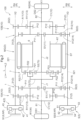
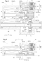
- FIGS. 1 to 4 a vehicle drive transmission device 100 according to a first embodiment will be described with reference to FIGS. 1 to 4 .
- the vehicle drive transmission device 100 includes a transmission 10.
- the vehicle drive transmission device 100 includes a pair of transmissions 10.
- the transmission 10 includes a planetary gear mechanism 1, a first fixing device 2, and a second fixing device 3.
- the planetary gear mechanism 1 includes an input element 11 drivingly connected to a drive source D for a wheel W (see FIG. 2 ), an output element 12 drivingly connected to the wheel W, a first stationary element 13, and a second stationary element 14.
- “drivingly connected” refers to a state in which two rotary elements are connected so that a driving force can be transmitted, and includes a state in which the two rotary elements are connected so as to rotate integrally or a state in which the two rotary elements are connected so that a driving force can be transmitted via one, two, or more transmission members.
- Such transmission members include various members that transmit rotation at the same speed or at a shifted speed, such as a shaft, a gear mechanism, a belt, and a chain.
- the transmission members may include an engagement device that selectively transmits rotation and a driving force, such as a friction engagement device and an intermesh engagement device.
- a rotary electric machine MG including a stator ST and a rotor RT corresponds to the drive source D.
- the "rotary electric machine” is used as a concept including any of a motor (electric motor), a generator (power generator), and a motor generator that functions as both a motor and a generator if necessary.
- the planetary gear mechanism 1 is disposed on a first axis X1 that is a rotation axis of the rotor RT of the rotary electric machine MG.
- the input element 11 is a sun gear S1.
- the output element 12 is a carrier C1.
- the first stationary element 13 includes a first annular portion A11 having an annular shape, and an internally toothed first ring gear R11 provided on the inner circumferential surface of the first annular portion A11.
- the second stationary element 14 includes a second annular portion A12 having an annular shape, and an internally toothed second ring gear R12 provided on the inner circumferential surface of the second annular portion A12.
- the carrier C1 rotatably supports large-diameter pinion gears P11 and small-diameter pinion gears P12 that rotate integrally with each other.
- Each of the large-diameter pinion gear P11 and the small-diameter pinion gear P12 rotates (spins) about its axis, and also rotates (revolves) about the sun gear S1 together with the carrier C1.
- a plurality of large-diameter pinion gears P11 and a plurality of small-diameter pinion gears P12 are provided at intervals along their revolution trajectories.
- the large-diameter pinion gear P11 meshes with both the sun gear S1 and the second ring gear R12.
- the large-diameter pinion gear P11 has a larger diameter than the sun gear S1.
- the small-diameter pinion gear P12 meshes with the first ring gear R11.
- the small-diameter pinion gear P12 has a smaller diameter than the large-diameter pinion gear P11.
- the first fixing device 2 is a device that selectively fixes the first stationary element 13 of the planetary gear mechanism 1 to a non-rotary member NR.
- the second fixing device 3 is a device that selectively fixes the second stationary element 14 of the planetary gear mechanism 1 to the non-rotary member NR.
- the non-rotary member NR is a case 9 that houses the components of the vehicle drive transmission device 100 including the transmission 10.
- the first fixing device 2 includes a first fixed gear 21, a first fixing gear 22, and a first friction engagement device 4.
- the first fixed gear 21 is connected to the first stationary element 13 of the planetary gear mechanism 1 so as to rotate integrally with the first stationary element 13.
- the first fixing gear 22 is disposed so as to mesh with the first fixed gear 21.
- the first fixed gear 21 is an externally toothed gear provided on the outer circumferential surface of the first annular portion A11.
- the first fixed gear 21 has a larger diameter than the large-diameter pinion gear P11.
- the first fixing gear 22 has a smaller diameter than the first fixed gear 21.
- the first fixed gear 21 is disposed on the first axis X1.
- the first fixing gear 22 is disposed on a second axis X2 different from the first axis X1.
- the first friction engagement device 4 is a device that selectively engages the first fixing gear 22 with the non-rotary member NR. The detailed configuration of the first friction engagement device 4 will be described later.
- the second fixing device 3 includes a second fixed gear 31, a second fixing gear 32, and a second friction engagement device 5.
- the second fixed gear 31 is connected to the second stationary element 14 of the planetary gear mechanism 1 so as to rotate integrally with the second stationary element 14.
- the second fixing gear 32 is disposed so as to mesh with the second fixed gear 31.
- the second fixed gear 31 is an externally toothed gear provided on the outer circumferential surface of the second annular portion A12.
- the second fixed gear 31 has a larger diameter than the large-diameter pinion gear P11.
- the second fixed gear 31 has the same diameter as the first fixed gear 21.
- the second fixing gear 32 has a smaller diameter than the second fixed gear 31.
- the second fixed gear 31 is disposed on the first axis X1.
- the second fixing gear 32 is disposed on a third axis X3 different from the first axis X1 and the second axis X2.
- the second friction engagement device 5 is a device that selectively engages the second fixing gear 32 with the non-rotary member NR. The detailed configuration of the second friction engagement device 5 will be described later.
- the rotation axis of the first fixing gear 22 (in this case, the second axis X2) and the rotation axis of the second fixing gear 32 (in this case, the third axis X3) are parallel to each other.
- the first axis X1, the second axis X2, and the third axis X3 are parallel to one another.
- axial direction L a direction along the rotation axis of the first fixing gear 22 (in this case, the second axis X2) and the rotation axis of the second fixing gear 32 (in this case, the third axis X3) will be referred to as "axial direction L.”
- first axial side L1 One side in the axial direction L
- second axial side L2 One side in the axial direction L
- a direction orthogonal to the rotation axis of the first fixing gear 22 (in this case, the second axis X2) will be referred to as "first radial direction RA.”
- a direction orthogonal to the rotation axis of the second fixing gear 32 (in this case, the third axis X3) will be referred to as "second radial direction RB.”
- a direction orthogonal to the rotation axis of any rotary member, including the first radial direction RA and the second radial direction RB will be referred to as "radial direction R.” That is, the radial direction R is defined based on the rotation axis of the rotary member such as the first fixing gear 22 or the second fixing gear 32.
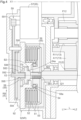
- the first friction engagement device 4 includes first friction members 41, second friction members 42, a first support member 43, a second support member 44, and a first pressing device 45.
- the first friction members 41 and the second friction members 42 are disposed on the second axis X2. That is, the first friction members 41 and the second friction members 42 are disposed coaxially with the first fixing gear 22.
- the first friction member 41 and the second friction member 42 are disposed so as to face each other in the axial direction L.
- a plurality of first friction members 41 and a plurality of second friction members 42 are provided, and these are disposed alternately along the axial direction L. Either the first friction members 41 or the second friction members 42 may be friction plates and the remaining may be separate plates.
- the first support member 43 is a member that supports the first friction members 41 in a state in which the relative rotation of the first friction members 41 is restricted.
- the first support member 43 is connected to the first fixing gear 22 so as to rotate integrally with the first fixing gear 22.
- the first support member 43 has a tubular shape extending along the axial direction L.
- the first support member 43 supports the outer circumferential portions of the first friction members 41.
- the second support member 44 is a member that supports the second friction members 42 in a state in which the relative rotation of the second friction members 42 is restricted.
- the second support member 44 is fixed to the non-rotary member NR.
- the second support member 44 has a tubular shape extending along the axial direction L.
- the second support member 44 supports the inner circumferential portions of the second friction members 42.
- the second support member 44 is fixed to a first support wall portion 91 of the case 9 that is the non-rotary member NR.
- the first support wall portion 91 is formed so as to extend along the first radial direction RA.
- the first support wall portion 91 is disposed so as to cover the first friction members 41 and the second friction members 42 from the first axial side L1.
- the second support member 44 is formed integrally with the first support wall portion 91 so as to protrude from the first support wall portion 91 to the second axial side L2.
- the first pressing device 45 is a device that presses the first friction members 41 and the second friction members 42 in the axial direction L.
- the first pressing device 45 includes a first pressing member 46 that applies a pressing force to the first friction members 41 and the second friction members 42, a first drive motor 47, and a screw-type first linear motion conversion mechanism 48 that converts the rotational driving force of the first drive motor 47 into a driving force in the axial direction L and transmits it to the first pressing member 46.
- the first drive motor 47 is a motor that generates a rotational driving force for driving the first pressing member 46.
- the first drive motor 47 is disposed on the outer side in the first radial direction RA with respect to the first support member 43, and is positioned to overlap the first support member 43 in a first radial view along the first radial direction RA.
- the first drive motor 47 is positioned to overlap the planetary gear mechanism 1 in the axial view along the axial direction L.
- the first linear motion conversion mechanism 48 includes a first screw shaft member 481, a first nut member 482, a first connecting member 483, a first supported member 484, and a first speed reducing mechanism 49.
- the first nut member 482 is supported so as to be movable in the axial direction L but not rotatable relative to the non-rotary member NR.
- the first nut member 482 is disposed on the inner side in the first radial direction RA with respect to the second support member 44 fixed to the non-rotary member NR.
- the first nut member 482 is connected to the second support member 44 so as to be movable relative to the second support member 44 in the axial direction L but not rotatable relative to the second support member 44 via an annular first anti-rotation member 48a disposed between the first nut member 482 and the second support member 44 in the first radial direction RA.
- annular first anti-rotation member 48a disposed between the first nut member 482 and the second support member 44 in the first radial direction RA.
- the first connecting member 483 connects the first screw shaft member 481 and the fourth gear 494.
- a gear connecting portion 495 extending from the fourth gear 494 to the second axial side L2 is connected to the first connecting member 483 so as to rotate integrally with the first connecting member 483 while being disposed on the inner side in the first radial direction RA with respect to the first connecting member 483.
- a plurality of spline teeth extending in the axial direction L is formed on the inner circumferential portion of the first connecting member 483 so as to be distributed in the circumferential direction.
- a plurality of spline teeth that engages with the plurality of spline teeth formed on the inner circumferential portion of the first connecting member 483 is formed on the outer circumferential portion of the gear connecting portion 495 so as to extend in the axial direction L and to be distributed in the circumferential direction.
- the first fixing gear 22 connected to the first support member 43 is fixed to the non-rotary member NR. Therefore, the first stationary element 13 connected so as to rotate integrally with the first fixed gear 21 that meshes with the first fixing gear 22 is fixed to the non-rotary member NR.
- the second friction engagement device 5 includes third friction members 51, fourth friction members 52, a third support member 53, a fourth support member 54, and a second pressing device 55.
- the third friction members 51 and the fourth friction members 52 are disposed on the third axis X3. That is, the third friction members 51 and the fourth friction members 52 are disposed coaxially with the second fixing gear 32.
- the third friction members 51 and the fourth friction members 52 are disposed so as to face each other in the axial direction L.
- a plurality of third friction members 51 and a plurality of fourth friction members 52 are provided, and these are disposed alternately along the axial direction L. Either the third friction members 51 or the fourth friction members 52 may be friction plates and the remaining may be separate plates.
- the third support member 53 is a member that supports the third friction members 51 in a state in which the relative rotation of the third friction members 51 is restricted.
- the third support member 53 is connected to the second fixing gear 32 so as to rotate integrally with the second fixing gear 32.
- the third support member 53 has a tubular shape extending along the axial direction L.
- the third support member 53 supports the outer circumferential portions of the third friction members 51.
- the fourth support member 54 is a member that supports the fourth friction members 52 in a state in which the relative rotation of the fourth friction members 52 is restricted.
- the fourth support member 54 is fixed to the non-rotary member NR.
- the fourth support member 54 has a tubular shape extending along the axial direction L.
- the fourth support member 54 supports the inner circumferential portions of the fourth friction members 52.
- the fourth support member 54 is fixed to a second support wall portion 92 of the case 9 that is the non-rotary member NR.
- the second support wall portion 92 is formed so as to extend along the second radial direction RB.
- the second support wall portion 92 is disposed so as to cover the third friction members 51 and the fourth friction members 52 from the first axial side L1.
- the fourth support member 54 is formed integrally with the second support wall portion 92 so as to protrude from the second support wall portion 92 to the second axial side L2.
- the second pressing device 55 is a device that presses the third friction members 51 and the fourth friction members 52 in the axial direction L.
- the second pressing device 55 includes a second pressing member 56 that applies a pressing force to the third friction members 51 and the fourth friction members 52, a second drive motor 57, and a screw-type second linear motion conversion mechanism 58 that converts the rotational driving force of the second drive motor 57 into a driving force in the axial direction L and transmits it to the second pressing member 56.
- the second pressing member 56 is positioned to overlap the third friction members 51 and the fourth friction members 52 in the axial view along the axial direction L.
- the second pressing member 56 has a plate shape extending along the second radial direction RB.
- the second drive motor 57 is a motor that generates a rotational driving force for driving the second pressing member 56.
- the second drive motor 57 is disposed on the outer side in the second radial direction RB with respect to the third support member 53, and is positioned to overlap the third support member 53 in a second radial view along the second radial direction RB.
- the second drive motor 57 is positioned to overlap the planetary gear mechanism 1 in the axial view along the axial direction L.
- the second linear motion conversion mechanism 58 includes a second screw shaft member 581, a second nut member 582, a second connecting member 583, a second supported member 584, and a second speed reducing mechanism 59.
- the second screw shaft member 581 is formed so as to extend along the axial direction L.
- the second nut member 582 has an annular shape that covers the second screw shaft member 581 from the outer side in the second radial direction RB.
- the second screw shaft member 581 and the second nut member 582 threadedly engage with each other.
- an external thread is formed on the outer circumferential portion of the second screw shaft member 581
- an internal thread that threadedly engages with the external thread of the second screw shaft member 581 is formed on the inner circumferential portion of the second nut member 582. Therefore, when the second screw shaft member 581 rotates, the second nut member 582 performs linear motion along the axial direction L according to the direction of the rotation and the directions of the external thread and the internal thread.
- the second nut member 582 is supported so as to be movable in the axial direction L but not rotatable relative to the non-rotary member NR.
- the second nut member 582 is disposed on the inner side in the second radial direction RB with respect to the fourth support member 54 fixed to the non-rotary member NR.
- the second nut member 582 is connected to the fourth support member 54 so as to be movable relative to the fourth support member 54 in the axial direction L but not rotatable relative to the fourth support member 54 via an annular second anti-rotation member 58a disposed between the second nut member 582 and the fourth support member 54 in the second radial direction RB.
- annular second anti-rotation member 58a disposed between the second nut member 582 and the fourth support member 54 in the second radial direction RB.
- a plurality of spline teeth extending in the axial direction L is formed on the outer circumferential portion of the second nut member 582 so as to be distributed in the circumferential direction.
- a plurality of spline teeth that engages with the plurality of spline teeth formed on the outer circumferential portion of the second nut member 582 is formed on the inner circumferential portion of the second anti-rotation member 58a so as to extend in the axial direction L and to be distributed in the circumferential direction.
- a plurality of spline teeth extending in the axial direction L is formed on the inner circumferential portion of the fourth support member 54 so as to be distributed in the circumferential direction.
- a plurality of spline teeth that engages with the plurality of spline teeth formed on the inner circumferential portion of the fourth support member 54 is formed on the outer circumferential portion of the second anti-rotation member 58a so as to extend in the axial direction L and to be distributed in the circumferential direction.
- the second nut member 582 is connected to the second pressing member 56 so as to move in the axial direction L integrally with the second pressing member 56.
- the second nut member 582 is formed integrally with the second pressing member 56. Therefore, the second pressing member 56 moves in the axial direction L via the second nut member 582 along with the rotation of the second screw shaft member 581.
- the second connecting member 583 connects the second screw shaft member 581 and the second speed reducing mechanism 59.
- the second connecting member 583 has a tubular shape extending from the second screw shaft member 581 to the first axial side L1.
- the second supported member 584 is supported in the axial direction L on the non-rotary member NR.
- the second supported member 584 is formed so as to protrude outward in the second radial direction RB from the second connecting member 583.
- the second supported member 584 is supported from the second axial side L2 via a second thrust bearing B2 on a supporting portion 54a formed so as to protrude inward in the second radial direction RB from the fourth support member 54 fixed to the non-rotary member NR.
- the second speed reducing mechanism 59 is configured to reduce the speed of rotation of the second drive motor 57.
- the second speed reducing mechanism 59 includes a fifth gear 591, a sixth gear 592, a seventh gear 593, and an eighth gear 594.
- the fifth gear 591 is connected to an output shaft of the second drive motor 57 so as to rotate integrally with the output shaft.
- the fifth gear 591 is disposed on the first axial side L1 with respect to the second drive motor 57.
- the sixth gear 592 meshes with the fifth gear 591.
- the sixth gear 592 has a larger diameter than the fifth gear 591.
- the seventh gear 593 is connected to the sixth gear 592 so as to rotate integrally with the sixth gear 592.
- the seventh gear 593 has a smaller diameter than the sixth gear 592.
- the seventh gear 593 is disposed on the second axial side L2 with respect to the sixth gear 592.
- the eighth gear 594 meshes with the seventh gear 593.
- the eighth gear 594 has a larger diameter than the seventh gear 593.
- the eighth gear 594 is disposed on the third axis X3.
- the number of teeth of the sixth gear 592 is larger than the number of teeth of the fifth gear 591.
- the number of teeth of the eighth gear 594 is larger than the number of teeth of the seventh gear 593 that rotates integrally with the sixth gear 592. Therefore, the rotation transmitted from the second drive motor 57 to the fifth gear 591 is transmitted to the seventh gear 593 with its speed reduced between the fifth gear 591 and the sixth gear 592. The speed of the rotation of the seventh gear 593 is reduced between the seventh gear 593 and the eighth gear 594.
- the second connecting member 583 connects the second screw shaft member 581 and the eighth gear 594.
- a gear connecting portion 595 extending from the eighth gear 594 to the second axial side L2 is connected to the second connecting member 583 so as to rotate integrally with the second connecting member 583 while being disposed on the inner side in the second radial direction RB with respect to the second connecting member 583.
- a plurality of spline teeth extending in the axial direction L is formed on the inner circumferential portion of the second connecting member 583 so as to be distributed in the circumferential direction.
- a plurality of spline teeth that engages with the plurality of spline teeth formed on the inner circumferential portion of the second connecting member 583 is formed on the outer circumferential portion of the gear connecting portion 595 so as to extend in the axial direction L and to be distributed in the circumferential direction.
- the second linear motion conversion mechanism 58 is disposed on the inner side in the second radial direction RB with respect to the third friction members 51 and the fourth friction members 52, and is positioned to overlap the third friction members 51 and the fourth friction members 52 in the second radial view along the second radial direction RB.
- the second screw shaft member 581, the second nut member 582, the second connecting member 583, and the second supported member 584 of the second linear motion conversion mechanism 58 are disposed on the inner side in the second radial direction RB with respect to the third friction members 51 and the fourth friction members 52, and are positioned to overlap the third friction members 51 and the fourth friction members 52 in the second radial view along the second radial direction RB.
- the second friction engagement device 5 when the second pressing member 56 moves to the first axial side L1 to press the third friction members 51 and the fourth friction members 52, the movement of the third friction members 51 and the fourth friction members 52 to the first axial side L1 is restricted by the second support wall portion 92 of the case 9 that is the non-rotary member NR. As a result, the third friction members 51 and the fourth friction members 52 are connected to each other so as not to be rotatable relative to each other, and the second friction engagement device 5 is engaged. Therefore, when the second friction engagement device 5 is engaged, the third support member 53 that supports the third friction members 51 is fixed to the fourth support member 54 fixed to the non-rotary member NR.
- the second fixing gear 32 connected to the third support member 53 is fixed to the non-rotary member NR. Therefore, the second stationary element 14 connected so as to rotate integrally with the second fixed gear 31 that meshes with the second fixing gear 32 is fixed to the non-rotary member NR.
- the first ring gear R11 having a relatively small diameter and meshing with the small-diameter pinion gear P12 is fixed to the non-rotary member NR.
- the second ring gear R12 having a relatively large diameter and meshing with the large-diameter pinion gear P11 is fixed to the non-rotary member NR.
- the carrier C1 that is the output element 12 is fixed to the non-rotary member NR.
- the wheel W drivingly connected to the output element 12 is locked.
- the first friction engagement device 4 and the second friction engagement device 5 function as a parking brake.
- the transmission 10 includes: the planetary gear mechanism 1 including the input element 11 drivingly connected to the drive source D for the wheel W, the output element 12 drivingly connected to the wheel W, the first stationary element 13, and the second stationary element 14; the first fixing device 2 configured to selectively fix the first stationary element 13 to the non-rotary member NR; and the second fixing device 3 configured to selectively fix the second stationary element 14 to the non-rotary member NR, in which the first fixing device 2 includes the first fixed gear 21 connected to the first stationary element 13 so as to rotate integrally with the first stationary element 13, the first fixing gear 22 that meshes with the first fixed gear 21, and the first friction engagement device 4 configured to selectively engage the first fixing gear 22 with the non-rotary member NR, the second fixing device 3 includes the second fixed gear 31 connected to the second stationary element 14 so as to rotate integrally with the second stationary element 14, the second fixing gear 32 that meshes with the second fixed gear 31, and the second friction engagement device 5 configured to selectively engage the second fixing gear 32 with the non-rotary member NR, the first friction engagement device
- the first fixing device 2 includes the first fixed gear 21 connected to the first stationary element 13 of the planetary gear mechanism 1 so as to rotate integrally with the first stationary element 13, the first fixing gear 22 that meshes with the first fixed gear 21, and the first friction engagement device 4 configured to selectively engage the first fixing gear 22 with the non-rotary member NR.
- the first friction engagement device 4 is disposed coaxially with the first fixing gear 22.
- the second fixing device 3 includes the second fixed gear 31 connected to the second stationary element 14 of the planetary gear mechanism 1 so as to rotate integrally with the second stationary element 14, the second fixing gear 32 that meshes with the second fixed gear 31, and the second friction engagement device 5 configured to selectively engage the second fixing gear 32 with the non-rotary member NR.
- the second friction engagement device 5 is disposed coaxially with the second fixing gear 32. Therefore, the first friction engagement device 4 and the second friction engagement device 5 can easily be disposed on different axes. Thus, the dimension of the transmission 10 in the axial direction L can easily be reduced compared to a configuration in which they are disposed coaxially.
- the diameter of the first fixing gear 22 is set smaller than that of the first fixed gear 21 in the first fixing device 2. Therefore, it is possible to reduce torque required to fix the first stationary element 13 of the planetary gear mechanism 1 to the non-rotary member NR.
- the diameter of the first friction engagement device 4 can be reduced easily.
- the diameter of the second friction engagement device 5 can be reduced easily.
- the transmission 10 can easily be downsized in the configuration including the pair of friction engagement devices 4, 5.
- the first friction engagement device 4 includes the first friction members 41 disposed coaxially with the first fixing gear 22, the second friction members 42 disposed coaxially with the first fixing gear 22 so as to face the first friction members 41 in the axial direction L, the first support member 43 connected to the first fixing gear 22 so as to rotate integrally with the first fixing gear 22 and supporting the first friction members 41 in a state in which the relative rotation of the first friction members 41 is restricted, the second support member 44 fixed to the non-rotary member NR and supporting the second friction members 42 in a state in which the relative rotation of the second friction members 42 is restricted, and the first pressing device 45 configured to press the first friction members 41 and the second friction members 42 in the axial direction L, the second friction engagement device 5 includes the third friction members 51 disposed coaxially with the second fixing gear 32, the fourth friction members 52 disposed coaxially with the second fixing gear 32 so as to face the third friction members 51 in the axial direction L, the third support member 53 connected to the second fixing gear 32 so as to rotate integrally with the
- the first friction engagement device 4 includes the first friction members 41, the second friction members 42, and the first support member 43 that are disposed coaxially with the first fixing gear 22. Therefore, the dimension of the first friction engagement device 4 in the radial direction R can easily be reduced compared to a configuration in which the first friction members 41, the second friction members 42, and the first support member 43 are disposed coaxially with the first stationary element 13 of the planetary gear mechanism 1. Similarly, in the second fixing device 3, the dimension of the second friction engagement device 5 in the radial direction R can easily be reduced compared to a configuration in which the third friction members 51, the fourth friction members 52, and the third support member 53 are disposed coaxially with the second stationary element 14 of the planetary gear mechanism 1.
- the first linear motion conversion mechanism 48 of the first pressing device 45 is disposed using the space on the inner side in the first radial direction RA with respect to the first friction members 41 and the second friction members 42
- the second linear motion conversion mechanism 58 of the second pressing device 55 is disposed using the space on the inner side in the second radial direction RB with respect to the third friction members 51 and the fourth friction members 52. Therefore, the first friction engagement device 4 including the first pressing device 45 and the second friction engagement device 5 including the second pressing device 55 can be downsized easily, and furthermore, the transmission 10 can be downsized easily.
- the first pressing member 46 operates in the axial direction L by the screw-type first linear motion conversion mechanism 48
- the second pressing member 56 operates in the axial direction L by the screw-type second linear motion conversion mechanism 58. Therefore, the positions of the first pressing member 46 and the second pressing member 56 can be maintained even when there is no driving force from the first drive motor 47 and the second drive motor 57.
- both the first friction engagement device 4 and the second friction engagement device 5 can be engaged, and the output element 12 of the planetary gear mechanism 1 can be locked so as not to rotate. This eliminates the need to provide a separate parking brake.
- the first stationary element 13 includes the first annular portion A11 having an annular shape, and the internally toothed first ring gear R11 provided on the inner circumferential surface of the first annular portion A11
- the second stationary element 14 includes the second annular portion A12 having an annular shape
- the internally toothed second ring gear R12 provided on the inner circumferential surface of the second annular portion A12
- the first fixed gear 21 is the externally toothed gear provided on the outer circumferential surface of the first annular portion A11
- the second fixed gear 31 is the externally toothed gear provided on the outer circumferential surface of the second annular portion A12.
- the first fixed gear 21 and the second fixed gear 31 can easily be disposed in the region on the outer side in the radial direction R with respect to the planetary gear mechanism 1. Therefore, the transmission 10 can easily be downsized in the configuration in which the first fixed gear 21 and the first fixing gear 22 mesh with each other and the second fixed gear 31 and the second fixing gear 32 mesh with each other.
- the vehicle drive transmission device 100 includes the pair of transmissions 10.
- one of the pair of transmissions 10 will be referred to as “first transmission 10A” and the other will be referred to as “second transmission 10B.”
- the vehicle drive transmission device 100 includes a rotor shaft 6, a differential gear mechanism 7, a first output member 81, and a second output member 82 in addition to the first transmission 10A and the second transmission 10B.
- the rotor shaft 6 is a shaft member that rotates integrally with the rotor RT of the rotary electric machine MG.
- the rotor shaft 6 is disposed on the first axis X1.
- the rotor shaft 6 has a tubular shape extending along the axial direction L.
- the rotor shaft 6 is disposed so as to support the rotor RT from the inner side in the radial direction R.
- the differential gear mechanism 7 includes a differential input element 71, a first differential output element 72, and a second differential output element 73.
- the differential gear mechanism 7 distributes, to the first differential output element 72 and the second differential output element 73, torque transmitted from the rotor shaft 6 to the differential input element 71.
- the differential gear mechanism 7 is disposed on the first axis X1.
- the differential input element 71 is an input element of the differential gear mechanism 7.
- the differential input element 71 is connected to the rotor shaft 6 so as to rotate integrally with the rotor shaft 6.
- the first differential output element 72 and the second differential output element 73 are output elements of the differential gear mechanism 7.
- the differential gear mechanism 7 is a planetary gear type differential gear mechanism including a differential sun gear S2, a differential carrier C2, and a differential ring gear R2.
- the differential gear mechanism 7 is a double-pinion type planetary gear mechanism. Therefore, the differential carrier C2 rotatably supports inner pinion gears P21 that mesh with the differential sun gear S2, and outer pinion gears P22 that mesh with the inner pinion gears P21 and the differential ring gear R2.
- the differential ring gear R2 is connected to the rotor shaft 6 so as to rotate integrally with the rotor shaft 6. That is, in the present embodiment, the differential ring gear R2 functions as the differential input element 71.
- the end of the rotor shaft 6 on the first axial side L1 extends outward in the radial direction R along the end face of the rotor RT on the first axial side L1, and is connected to the differential ring gear R2.
- the differential carrier C2 functions as the first differential output element 72.
- the differential sun gear S2 functions as the second differential output element 73.
- the first output member 81 is drivingly connected to a first wheel W1 (see FIG. 2 ) that is the wheel W described above.
- the second output member 82 is drivingly connected to a second wheel W2 (see FIG. 2 ) that is the wheel W described above and is different from the first wheel W1.
- the first output member 81 is connected to the first wheel W1 via a first drive shaft DS1 (see FIG. 2 ) so as to rotate integrally with the first wheel W1.
- the second output member 82 is connected to the second wheel W2 via a second drive shaft DS2 (see FIG. 2 ) so as to rotate integrally with the second wheel W2.
- the first output member 81 and the second output member 82 are disposed on the first axis X1.
- the first wheel W1 and the second wheel W2 are a pair of right and left wheels (e.g., a pair of right and left front wheels or a pair of right and left rear wheels).
- the planetary gear mechanism 1 of the first transmission 10A, the differential gear mechanism 7, the rotary electric machine MG, and the planetary gear mechanism 1 of the second transmission 10B are disposed on the first axis X1 in the stated order from the first axial side L1 to the second axial side L2. That is, in the present embodiment, the planetary gear mechanism 1 of the first transmission 10A and the planetary gear mechanism 1 of the second transmission 10B are disposed separately on both sides in the axial direction L with respect to the rotary electric machine MG and the differential gear mechanism 7.
- the input element 11 of the first transmission 10A is connected to the first differential output element 72 so as to rotate integrally with the first differential output element 72.
- the sun gear S1 that is the input element 11 of the first transmission 10A is connected to the differential carrier C2 that is the first differential output element 72 via a first connecting shaft J1 so as to rotate integrally with the differential carrier C2.
- the first connecting shaft J1 is a shaft member extending along the axial direction L so as to connect the sun gear S1 of the first transmission 10A and the differential carrier C2.
- the output element 12 of the first transmission 10A is connected to the first output member 81 so as to rotate integrally with the first output member 81.
- the carrier C1 that is the output element 12 of the first transmission 10A is formed integrally with the first output member 81.
- the input element 11 of the second transmission 10B is connected to the second differential output element 73 so as to rotate integrally with the second differential output element 73.
- the sun gear S1 that is the input element 11 of the second transmission 10B is connected to the differential sun gear S2 that is the second differential output element 73 via a second connecting shaft J2 so as to rotate integrally with the differential sun gear S2.
- the second connecting shaft J2 is a shaft member extending along the axial direction L so as to connect the sun gear S1 of the second transmission 10B and the differential sun gear S2.
- the second connecting shaft J2 is disposed so as to extend through the rotor shaft 6 in the axial direction L on the inner side in the radial direction R with respect to the rotor shaft 6.
- the output element 12 of the second transmission 10B is connected to the second output member 82 so as to rotate integrally with the second output member 82.
- the carrier C1 that is the output element 12 of the second transmission 10B is formed integrally with the second output member 82.
- the first fixed gear 21 of the first transmission 10A and the first fixed gear 21 of the second transmission 10B are disposed on the first axis X1. That is, the first fixed gear 21 of the first transmission 10A and the first fixed gear 21 of the second transmission 10B are disposed coaxially.
- the second fixed gear 31 of the first transmission 10A and the second fixed gear 31 of the second transmission 10B are disposed on the first axis X1. That is, the second fixed gear 31 of the first transmission 10A and the second fixed gear 31 of the second transmission 10B are disposed coaxially.
- the first fixing gear 22 of the first transmission 10A and the first fixing gear 22 of the second transmission 10B are disposed on the second axis X2. That is, the first fixing gear 22 of the first transmission 10A and the first fixing gear 22 of the second transmission 10B are disposed coaxially.
- the first fixing gear 22 of the first transmission 10A and the first fixing gear 22 of the second transmission 10B are connected to each other so as to rotate integrally with each other.
- the first fixing gear 22 of the first transmission 10A and the first fixing gear 22 of the second transmission 10B are connected to each other via a first fixing gear connecting member 221 so as to rotate integrally with each other.
- the first fixing gear connecting member 221 is a shaft member formed so as to extend along the axial direction L.
- the second fixing gear 32 of the first transmission 10A and the second fixing gear 32 of the second transmission 10B are disposed on the third axis X3. That is, the second fixing gear 32 of the first transmission 10A and the second fixing gear 32 of the second transmission 10B are disposed coaxially.
- the second fixing gear 32 of the first transmission 10A and the second fixing gear 32 of the second transmission 10B are connected to each other so as to rotate integrally with each other.
- the second fixing gear 32 of the first transmission 10A and the second fixing gear 32 of the second transmission 10B are connected to each other via a second fixing gear connecting member 321 so as to rotate integrally with each other.
- the second fixing gear connecting member 321 is a shaft member formed so as to extend along the axial direction L.
- the first fixing gear 22 of the first transmission 10A and the first fixing gear 22 of the second transmission 10B are connected to the first support member 43 of the first friction engagement device 4 via the first fixing gear connecting member 221 so as to rotate integrally with the first support member 43. Therefore, when the first friction engagement device 4 is engaged, the first fixing gear 22 of the first transmission 10A and the first fixing gear 22 of the second transmission 10B are fixed to the non-rotary member NR. When the first friction engagement device 4 is disengaged, the first fixing gear 22 of the first transmission 10A and the first fixing gear 22 of the second transmission 10B become rotatable relative to the non-rotary member NR. In this way, in the present embodiment, the first transmission 10A and the second transmission 10B share the single first friction engagement device 4. That is, in the present embodiment, the first friction engagement device 4 of the first transmission 10A and the first friction engagement device 4 of the second transmission 10B are common to each other.
- the second fixing gear 32 of the first transmission 10A and the second fixing gear 32 of the second transmission 10B are connected to the third support member 53 of the second friction engagement device 5 via the second fixing gear connecting member 321 so as to rotate integrally with the third support member 53. Therefore, when the second friction engagement device 5 is engaged, the second fixing gear 32 of the first transmission 10A and the second fixing gear 32 of the second transmission 10B are fixed to the non-rotary member NR. When the second friction engagement device 5 is disengaged, the second fixing gear 32 of the first transmission 10A and the second fixing gear 32 of the second transmission 10B become rotatable relative to the non-rotary member NR. In this way, in the present embodiment, the first transmission 10A and the second transmission 10B share the single second friction engagement device 5. That is, in the present embodiment, the second friction engagement device 5 of the first transmission 10A and the second friction engagement device 5 of the second transmission 10B are common to each other.
- the drive source D is the rotary electric machine MG including the rotor RT
- the vehicle drive transmission device 100 includes: the rotor shaft 6 configured to rotate integrally with the rotor RT; the first output member 81 drivingly connected to the first wheel W1 that is the wheel W; the second output member 82 drivingly connected to the second wheel W2 that is the wheel W and is different from the first wheel W1; the differential gear mechanism 7 including the differential input element 71 connected to the rotor shaft 6 so as to rotate integrally with the rotor shaft 6, the first differential output element 72, and the second differential output element 73, and configured to distribute, to the first differential output element 72 and the second differential output element 73, torque transmitted from the rotor shaft 6 to the differential input element 71; the first transmission 10A that is the transmission 10 described above; and the second transmission 10B that is the transmission 10 described above and is different from the first transmission 10A, the input element 11 of the first transmission 10A is connected to the first differential output element 72 so as to rotate integrally
- the first fixing gears 22 constituting the first fixing devices 2 of the pair of transmissions 10 are disposed coaxially and connected to each other so as to rotate integrally with each other.
- the second fixing gears 32 constituting the second fixing devices 3 of the pair of transmissions 10 are disposed coaxially and connected to each other so as to rotate integrally with each other.
- the pair of first fixing gears 22 can selectively be engaged with the non-rotary member NR by the single first friction engagement device 4, and the pair of second fixing gears 32 can selectively be engaged with the non-rotary member NR by the single second friction engagement device 5.
- the pair of first fixing devices 2 and the pair of second fixing devices 3 can be downsized easily, and furthermore, the vehicle drive transmission device 100 can be downsized easily in the configuration including the pair of transmissions 10.
- the first friction engagement device 4 and the second friction engagement device 5 are disposed such that their disposition areas in the axial direction L overlap each other.
- the first friction engagement device 4 and the second friction engagement device 5 are disposed so as not to overlap each other in the axial view along the axial direction L.
- the first friction engagement device 4 and the second friction engagement device 5 may be disposed away from each other in the axial direction L.
- the first friction engagement device 4 and the second friction engagement device 5 may be disposed separately on both sides in the axial direction L with respect to the rotary electric machine MG and the planetary gear mechanisms 1 of the pair of transmissions 10.
- the first friction engagement device 4 and the second friction engagement device 5 may be disposed so as to overlap each other in the axial view along the axial direction L.
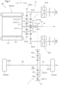
- the vehicle drive transmission device 100 includes one transmission 10, and the position of the transmission 10 in the power transmission path connecting the drive source D to the first output member 81 and the second output member 82 is different from that in the first embodiment.
- the following description focuses on the differences from the first embodiment. Points that are not particularly described are the same as in the first embodiment.
- the input element 11 of the transmission 10 includes a first sun gear S11 and a second sun gear S12 that rotate integrally with each other.
- the first sun gear S11 meshes with the small-diameter pinion gears P12.
- the second sun gear S12 meshes with the large-diameter pinion gears P11.
- the second sun gear S12 has a smaller diameter than the first sun gear S11.
- the large-diameter pinion gears P11 and the small-diameter pinion gears P12 are supported so as to be rotatable relative to each other.
- the second ring gear R12 that meshes with the large-diameter pinion gears P11 and the first ring gear R11 that meshes with the small-diameter pinion gears P12 have the same diameter.
- the first fixed gear 21 that rotates integrally with the first ring gear R11 has a smaller diameter than the second fixed gear 31 that rotates integrally with the second ring gear R12.
- the input element 11 of the transmission 10 is connected to the rotor shaft 6 so as to rotate integrally with the rotor shaft 6.
- the first sun gear S11 and the second sun gear S12 that are the input element 11 are formed on an input shaft 15 connected to the rotor shaft 6 so as to rotate integrally with the rotor shaft 6.
- the second sun gear S12 is disposed on the second axial side L2 with respect to the first sun gear S11.
- the output element 12 of the transmission 10 is connected to an externally toothed driving gear 16 so as to rotate integrally with the driving gear 16.
- the driving gear 16 is disposed on the first axis X1.
- the driving gear 16 is disposed on the second axial side L2 with respect to the planetary gear mechanism 1 of the transmission 10.
- the driving gear 16 is disposed on the outer side in the radial direction R with respect to the input shaft 15.
- the differential gear mechanism 7 is not disposed on the first axis X1, but is disposed on a fourth axis X4 different from the first axis X1, the second axis X2, and the third axis X3.
- the differential input element 71 of the differential gear mechanism 7 is connected to an externally toothed driven gear 74 that meshes with the driving gear 16 so as to rotate integrally with the driven gear 74.
- the driven gear 74 is disposed on the fourth axis X4.
- the driven gear 74 is disposed on the outer side in the radial direction R with respect to the differential ring gear R2 that is the differential input element 71, and is positioned to overlap the differential ring gear R2 in the radial view along the radial direction R.
- the first differential output element 72 of the differential gear mechanism 7 is connected to the first output member 81 so as to rotate integrally with the first output member 81.
- the second differential output element 73 of the differential gear mechanism 7 is connected to the second output member 82 so as to rotate integrally with the second output member 82.
- the first output member 81 is formed so as to extend from the differential carrier C2 that is the first differential output element 72 to the second axial side L2.
- the second output member 82 is formed so as to extend from the differential sun gear S2 that is the second differential output element 73 to the first axial side L1.
- the differential gear mechanism 7 distributes, to the first differential output element 72 and the second differential output element 73, torque transmitted from the transmission 10 to the differential input element 71.
- the first axis X1, the second axis X2, the third axis X3, and the fourth axis X4 are parallel to one another.
- the second axis X2, the third axis X3, and the fourth axis X4 surround the first axis X1.
- the first axis X1 is in a triangle (in this case, an acute triangle) whose vertices are the second axis X2, the third axis X3, and the fourth axis X4.
- the drive source D is the rotary electric machine MG including the rotor RT
- the vehicle drive transmission device 100 includes: the rotor shaft 6 configured to rotate integrally with the rotor RT; the first output member 81 drivingly connected to the first wheel W1 that is the wheel W; the second output member 82 drivingly connected to the second wheel W2 that is the wheel W and is different from the first wheel W1; the transmission 10 described above; and the differential gear mechanism 7 including the differential input element 71, the first differential output element 72, and the second differential output element 73, and configured to distribute, to the first differential output element 72 and the second differential output element 73, torque transmitted from the transmission 10 to the differential input element 71, the input element 11 of the transmission 10 is connected to the rotor shaft 6 so as to rotate integrally with the rotor shaft 6, the output element 12 of the transmission 10 is connected to the externally toothed driving gear 16 so as to rotate integrally with the driving gear 16, the differential input element 71 is connected to the externally toothed driven
- the second axis X2 on which the first fixing gear 22 of the transmission 10 is disposed, the third axis X3 on which the second fixing gear 32 of the transmission 10 is disposed, and the fourth axis X4 on which the differential gear mechanism 7 is disposed surround the first axis X1 on which the rotor shaft 6 and the planetary gear mechanism 1 of the transmission 10 are disposed. Therefore, the dimension of the vehicle drive transmission device 100 in the radial direction R with respect to the first axis X1 can be reduced easily.
- a vehicle drive transmission device 100 according to a third embodiment will be described with reference to FIG. 9 .
- the configuration of the transmission 10 is different from that in the second embodiment.
- the following description focuses on the differences from the second embodiment. Points that are not particularly described are the same as in the second embodiment.
- the input element 11 of the transmission 10 is the sun gear S1.
- the output element 12 of the transmission 10 is the second ring gear R12.
- the first stationary element 13 is the first ring gear R11.
- the second stationary element 14 is the carrier C1.
- the carrier C1 rotatably supports the large-diameter pinion gears P11 and the small-diameter pinion gears P12 that rotate integrally with each other.
- the large-diameter pinion gear P11 meshes with both the sun gear S1 and the second ring gear R12.
- the large-diameter pinion gear P11 has a smaller diameter than the sun gear S1.
- the small-diameter pinion gear P12 meshes with the first ring gear R11.
- the second fixed gear 31 is connected to the carrier C1 that is the second stationary element 14 so as to rotate integrally with the carrier C1.
- the second fixed gear 31 is disposed on the second axial side L2 with respect to the planetary gear mechanism 1.
- the driving gear 16 is connected to the second ring gear R12 that is the output element 12 so as to rotate integrally with the second ring gear R12.
- the driving gear 16 is disposed on the first axial side L1 with respect to the planetary gear mechanism 1.
- the transmission (10) includes: a planetary gear mechanism (1) including an input element (11) drivingly connected to a drive source (D) for a wheel (W), an output element (12) drivingly connected to the wheel (W), a first stationary element (13), and a second stationary element (14); a first fixing device (2) configured to selectively fix the first stationary element (13) to a non-rotary member (NR); and a second fixing device (3) configured to selectively fix the second stationary element (14) to the non-rotary member (NR), in which the first fixing device (2) includes a first fixed gear (21) connected to the first stationary element (13) so as to rotate integrally with the first stationary element (13), a first fixing gear (22) that meshes with the first fixed gear (21), and a first friction engagement device (4) configured to selectively engage the first fixing gear (22) with the non-rotary member (NR), the second fixing device (3) includes a second fixed gear (31) connected to the second stationary element (14) so as to rotate integrally with the second stationary element (14), a second fixing gear (32) that meshes with
- the first fixing device (2) includes the first fixed gear (21) connected to the first stationary element (13) of the planetary gear mechanism (1) so as to rotate integrally with the first stationary element (13), the first fixing gear (22) that meshes with the first fixed gear (21), and the first friction engagement device (4) configured to selectively engage the first fixing gear (22) with the non-rotary member (NR).
- the first friction engagement device (4) is disposed coaxially with the first fixing gear (22).
- the second fixing device (3) includes the second fixed gear (31) connected to the second stationary element (14) of the planetary gear mechanism (1) so as to rotate integrally with the second stationary element (14), the second fixing gear (32) that meshes with the second fixed gear (31), and the second friction engagement device (5) configured to selectively engage the second fixing gear (32) with the non-rotary member (NR).
- the second friction engagement device (5) is disposed coaxially with the second fixing gear (32). Therefore, the first friction engagement device (4) and the second friction engagement device (5) can easily be disposed on different axes. Thus, the dimension of the transmission (10) in the axial direction (L) can easily be reduced compared to a configuration in which they are disposed coaxially.
- the diameter of the first fixing gear (22) is set smaller than that of the first fixed gear (21) in the first fixing device (2). Therefore, it is possible to reduce torque required to fix the first stationary element (13) of the planetary gear mechanism (1) to the non-rotary member (NR).
- the diameter of the first friction engagement device (4) can be reduced easily.
- the diameter of the second friction engagement device (5) can be reduced easily.
- the transmission (10) can easily be downsized in the configuration including the pair of friction engagement devices (4, 5).
- the first friction engagement device (4) include a first friction member (41) disposed coaxially with the first fixing gear (22), a second friction member (42) disposed coaxially with the first fixing gear (22) so as to face the first friction member (41) in the axial direction (L), a first support member (43) connected to the first fixing gear (22) so as to rotate integrally with the first fixing gear (22) and supporting the first friction member (41) in a state in which relative rotation of the first friction member (41) is restricted, a second support member (44) fixed to the non-rotary member (NR) and supporting the second friction member (42) in a state in which relative rotation of the second friction member (42) is restricted, and a first pressing device (45) configured to press the first friction member (41) and the second friction member (42) in the axial direction (L), the second friction engagement device (5) include a third friction member (51) disposed coaxially with the second fixing gear (32), a fourth friction member (52) disposed coaxially with the second fixing gear (32) so as to face the third friction member
- the first friction engagement device (4) includes the first friction member (41), the second friction member (42), and the first support member (43) that are disposed coaxially with the first fixing gear (22). Therefore, the dimension of the first friction engagement device (4) in the radial direction (R) can easily be reduced compared to a configuration in which the first friction member (41), the second friction member (42), and the first support member (43) are disposed coaxially with the first stationary element (13) of the planetary gear mechanism (1).
- the dimension of the second friction engagement device (5) in the radial direction (R) can easily be reduced compared to a configuration in which the third friction member (51), the fourth friction member (52), and the third support member (53) are disposed coaxially with the second stationary element (14) of the planetary gear mechanism (1).
- the first linear motion conversion mechanism (48) of the first pressing device (45) is disposed using the space on the inner side in the first radial direction (RA) with respect to the first friction member (41) and the second friction member (42), and the second linear motion conversion mechanism (58) of the second pressing device (55) is disposed using the space on the inner side in the second radial direction (RB) with respect to the third friction member (51) and the fourth friction member (52). Therefore, the first friction engagement device (4) including the first pressing device (45) and the second friction engagement device (5) including the second pressing device (55) can be downsized easily, and furthermore, the transmission (10) can be downsized easily.
- the first pressing member (46) operates in the axial direction (L) by the screw-type first linear motion conversion mechanism (48), and the second pressing member (56) operates in the axial direction (L) by the screw-type second linear motion conversion mechanism (58). Therefore, the positions of the first pressing member (46) and the second pressing member (56) can be maintained even when there is no driving force from the first drive motor (47) and the second drive motor (57). Thus, even when no electric power is supplied to the transmission (10), both the first friction engagement device (4) and the second friction engagement device (5) can be engaged, and the output element (12) of the planetary gear mechanism (1) can be locked so as not to rotate. This eliminates the need to provide a separate parking brake.
- the drive source (D) be a rotary electric machine (MG) including a rotor (RT)
- the vehicle drive transmission device (100) include: a rotor shaft (6) configured to rotate integrally with the rotor (RT); a first output member (81) drivingly connected to a first wheel (W1) that is the wheel (W); a second output member (82) drivingly connected to a second wheel (W2) that is the wheel (W) and is different from the first wheel (W1); a differential gear mechanism (7) including a differential input element (71) connected to the rotor shaft (6) so as to rotate integrally with the rotor shaft (6), a first differential output element (72), and a second differential output element (73) , and configured to distribute, to the first differential output element (72) and the second differential output element (73), torque transmitted from the rotor shaft (6) to the differential input element (71); a first transmission (10A) that is the transmission (10) described above; and a second transmission (10B) that is the transmission (10) described above and is
- the first fixing gears (22) constituting the first fixing devices (2) of the pair of transmissions (10) are disposed coaxially and connected to each other so as to rotate integrally with each other.
- the second fixing gears (32) constituting the second fixing devices (3) of the pair of transmissions (10) are disposed coaxially and connected to each other so as to rotate integrally with each other.
- the pair of first fixing gears (22) can selectively be engaged with the non-rotary member (NR) by the single first friction engagement device (4), and the pair of second fixing gears (32) can selectively be engaged with the non-rotary member (NR) by the single second friction engagement device (5).
- the pair of first fixing devices (2) and the pair of second fixing devices (3) can be downsized easily, and furthermore, the vehicle drive transmission device (100) can be downsized easily in the configuration including the pair of transmissions (10).
- the drive source (D) be a rotary electric machine (MG) including a rotor (RT)
- the vehicle drive transmission device (100) include: a rotor shaft (6) configured to rotate integrally with the rotor (RT); a first output member (81) drivingly connected to a first wheel (W1) that is the wheel (W); a second output member (82) drivingly connected to a second wheel (W2) that is the wheel (W) and is different from the first wheel (W1); the transmission (10) described above; and a differential gear mechanism (7) including a differential input element (71), a first differential output element (72), and a second differential output element (73), and configured to distribute, to the first differential output element (72) and the second differential output element (73), torque transmitted from the transmission (10) to the differential input element (71), the input element (11) of the transmission (10) be connected to the rotor shaft (6) so as to rotate integrally with the rotor shaft (6), the output element (12) of the transmission (10) be connected to an externally toothe
- the second axis (X2) on which the first fixing gear (22) of the transmission (10) is disposed, the third axis (X3) on which the second fixing gear (32) of the transmission (10) is disposed, and the fourth axis (X4) on which the differential gear mechanism (7) is disposed surround the first axis (X1) on which the rotor shaft (6) and the planetary gear mechanism (1) of the transmission (10) are disposed. Therefore, the dimension of the vehicle drive transmission device (100) in the radial direction (R) with respect to the first axis (X1) can be reduced easily.
- the technology disclosed herein is applicable to a transmission including a planetary gear mechanism including an input element drivingly connected to a drive source for a wheel, an output element drivingly connected to the wheel, a first stationary element, and a second stationary element, a first fixing device that selectively fixes the first stationary element to a non-rotary member, and a second fixing device that selectively fixes the second stationary element to the non-rotary member, and a vehicle drive transmission device including the transmission.
Landscapes
- Engineering & Computer Science (AREA)
- General Engineering & Computer Science (AREA)
- Mechanical Engineering (AREA)
- Chemical & Material Sciences (AREA)
- Combustion & Propulsion (AREA)
- Transportation (AREA)
- Retarders (AREA)
Applications Claiming Priority (2)
| Application Number | Priority Date | Filing Date | Title |
|---|---|---|---|
| JP2022153925 | 2022-09-27 | ||
| PCT/JP2023/026241 WO2024070143A1 (fr) | 2022-09-27 | 2023-07-18 | Transmission et dispositif de transmission d'entraînement de véhicule équipé de celle-ci |
Publications (2)
| Publication Number | Publication Date |
|---|---|
| EP4556747A1 true EP4556747A1 (fr) | 2025-05-21 |
| EP4556747A4 EP4556747A4 (fr) | 2025-11-19 |
Family
ID=90476957
Family Applications (1)
| Application Number | Title | Priority Date | Filing Date |
|---|---|---|---|
| EP23871387.9A Pending EP4556747A4 (fr) | 2022-09-27 | 2023-07-18 | Transmission et dispositif de transmission d'entraînement de véhicule équipé de celle-ci |
Country Status (4)
| Country | Link |
|---|---|
| EP (1) | EP4556747A4 (fr) |
| JP (1) | JP7708326B2 (fr) |
| CN (1) | CN119895173A (fr) |
| WO (1) | WO2024070143A1 (fr) |
Family Cites Families (6)
| Publication number | Priority date | Publication date | Assignee | Title |
|---|---|---|---|---|
| JP6028507B2 (ja) * | 2011-10-28 | 2016-11-16 | 日本精工株式会社 | 電気自動車用駆動装置 |
| JP2013200012A (ja) | 2012-03-26 | 2013-10-03 | Aisin Aw Co Ltd | ブレーキ装置及び動力伝達装置 |
| US8556758B1 (en) * | 2013-02-07 | 2013-10-15 | GM Global Technology Operations LLC | Hybrid powertrain |
| KR101816794B1 (ko) * | 2016-08-29 | 2018-01-10 | 이엠티씨 주식회사 | 3단 변속장치 |
| DE102018218183A1 (de) * | 2018-10-24 | 2020-04-30 | Robert Bosch Gmbh | Lastschaltbares Mehrganggetriebe |
| DE102020112624A1 (de) * | 2020-05-11 | 2021-11-11 | Schaeffler Technologies AG & Co. KG | Getriebeeinrichtung für einen elektrischen Antrieb eines Fahrzeuges |
-
2023
- 2023-07-18 JP JP2024549772A patent/JP7708326B2/ja active Active
- 2023-07-18 EP EP23871387.9A patent/EP4556747A4/fr active Pending
- 2023-07-18 WO PCT/JP2023/026241 patent/WO2024070143A1/fr not_active Ceased
- 2023-07-18 CN CN202380066901.8A patent/CN119895173A/zh active Pending
Also Published As
| Publication number | Publication date |
|---|---|
| CN119895173A (zh) | 2025-04-25 |
| JP7708326B2 (ja) | 2025-07-15 |
| EP4556747A4 (fr) | 2025-11-19 |
| WO2024070143A1 (fr) | 2024-04-04 |
| JPWO2024070143A1 (fr) | 2024-04-04 |
Similar Documents
| Publication | Publication Date | Title |
|---|---|---|
| CN100358744C (zh) | 复合驱动装置及搭载该装置的汽车 | |
| KR102173857B1 (ko) | 동력 전달 장치 | |
| US5554082A (en) | Transmission with integral large and small planetary gears, and method of assembling the transmission | |
| US20250018788A1 (en) | Drive device for vehicle | |
| US11015683B2 (en) | Vehicle driving device | |
| EP3663609B1 (fr) | Dispositif de commande destiné à un véhicule | |
| WO2021039966A1 (fr) | Dispositif d'entraînement de véhicule | |
| EP3663611B1 (fr) | Dispositif d'entraînement pour véhicule | |
| JP7694685B2 (ja) | 車両用駆動装置 | |
| EP4556747A1 (fr) | Transmission et dispositif de transmission d'entraînement de véhicule équipé de celle-ci | |
| WO2018181557A1 (fr) | Dispositif d'entraînement pour véhicule | |
| EP1389696A2 (fr) | Changement de vitesse pour boíte de vitesses automatique | |
| JP7835312B2 (ja) | 車両用変速機 | |
| JP2025065710A (ja) | 変速機 | |
| JP2024043033A (ja) | 車両用駆動伝達装置 | |
| JP2019049320A (ja) | 車両用駆動装置 | |
| JP2024065898A (ja) | 車両用駆動伝達装置 | |
| JP2000046129A (ja) | 車両用自動変速機 | |
| JP2024126145A (ja) | 車両用駆動伝達装置、及びそれを備えた車両用駆動装置 | |
| JP7739941B2 (ja) | 車両用駆動装置 | |
| JP7476761B2 (ja) | 車両用駆動装置 | |
| JP4682876B2 (ja) | 自動変速機 | |
| JP2024050214A (ja) | 車両用駆動伝達装置 | |
| JP2024050213A (ja) | 車両用駆動伝達装置 | |
| JP2023140264A (ja) | 車両用駆動装置 |
Legal Events
| Date | Code | Title | Description |
|---|---|---|---|
| STAA | Information on the status of an ep patent application or granted ep patent |
Free format text: STATUS: THE INTERNATIONAL PUBLICATION HAS BEEN MADE |
|
| PUAI | Public reference made under article 153(3) epc to a published international application that has entered the european phase |
Free format text: ORIGINAL CODE: 0009012 |
|
| STAA | Information on the status of an ep patent application or granted ep patent |
Free format text: STATUS: REQUEST FOR EXAMINATION WAS MADE |
|
| 17P | Request for examination filed |
Effective date: 20241125 |
|
| AK | Designated contracting states |
Kind code of ref document: A1 Designated state(s): AL AT BE BG CH CY CZ DE DK EE ES FI FR GB GR HR HU IE IS IT LI LT LU LV MC ME MK MT NL NO PL PT RO RS SE SI SK SM TR |
|
| A4 | Supplementary search report drawn up and despatched |
Effective date: 20251022 |
|
| RIC1 | Information provided on ipc code assigned before grant |
Ipc: F16H 3/54 20060101AFI20251016BHEP Ipc: F16H 3/66 20060101ALI20251016BHEP |
|
| DAV | Request for validation of the european patent (deleted) | ||
| DAX | Request for extension of the european patent (deleted) |