EP4556768A1 - Rückschlagventil und luftrückschlagbehälter - Google Patents
Rückschlagventil und luftrückschlagbehälter Download PDFInfo
- Publication number
- EP4556768A1 EP4556768A1 EP23815329.0A EP23815329A EP4556768A1 EP 4556768 A1 EP4556768 A1 EP 4556768A1 EP 23815329 A EP23815329 A EP 23815329A EP 4556768 A1 EP4556768 A1 EP 4556768A1
- Authority
- EP
- European Patent Office
- Prior art keywords
- valve
- air
- return
- container
- lip portion
- Prior art date
- Legal status (The legal status is an assumption and is not a legal conclusion. Google has not performed a legal analysis and makes no representation as to the accuracy of the status listed.)
- Pending
Links
Images

Classifications
-
- A—HUMAN NECESSITIES
- A61—MEDICAL OR VETERINARY SCIENCE; HYGIENE
- A61J—CONTAINERS SPECIALLY ADAPTED FOR MEDICAL OR PHARMACEUTICAL PURPOSES; DEVICES OR METHODS SPECIALLY ADAPTED FOR BRINGING PHARMACEUTICAL PRODUCTS INTO PARTICULAR PHYSICAL OR ADMINISTERING FORMS; DEVICES FOR ADMINISTERING FOOD OR MEDICINES ORALLY; BABY COMFORTERS; DEVICES FOR RECEIVING SPITTLE
- A61J9/00—Feeding-bottles in general
- A61J9/04—Feeding-bottles in general with means for supplying air
-
- A—HUMAN NECESSITIES
- A61—MEDICAL OR VETERINARY SCIENCE; HYGIENE
- A61J—CONTAINERS SPECIALLY ADAPTED FOR MEDICAL OR PHARMACEUTICAL PURPOSES; DEVICES OR METHODS SPECIALLY ADAPTED FOR BRINGING PHARMACEUTICAL PRODUCTS INTO PARTICULAR PHYSICAL OR ADMINISTERING FORMS; DEVICES FOR ADMINISTERING FOOD OR MEDICINES ORALLY; BABY COMFORTERS; DEVICES FOR RECEIVING SPITTLE
- A61J11/00—Teats
- A61J11/0075—Accessories therefor
- A61J11/008—Protecting caps
-
- F—MECHANICAL ENGINEERING; LIGHTING; HEATING; WEAPONS; BLASTING
- F16—ENGINEERING ELEMENTS AND UNITS; GENERAL MEASURES FOR PRODUCING AND MAINTAINING EFFECTIVE FUNCTIONING OF MACHINES OR INSTALLATIONS; THERMAL INSULATION IN GENERAL
- F16K—VALVES; TAPS; COCKS; ACTUATING-FLOATS; DEVICES FOR VENTING OR AERATING
- F16K15/00—Check valves
- F16K15/14—Check valves with flexible valve members
- F16K15/144—Check valves with flexible valve members the closure elements being fixed along all or a part of their periphery
- F16K15/147—Check valves with flexible valve members the closure elements being fixed along all or a part of their periphery the closure elements having specially formed slits or being of an elongated easily collapsible form
-
- F—MECHANICAL ENGINEERING; LIGHTING; HEATING; WEAPONS; BLASTING
- F16—ENGINEERING ELEMENTS AND UNITS; GENERAL MEASURES FOR PRODUCING AND MAINTAINING EFFECTIVE FUNCTIONING OF MACHINES OR INSTALLATIONS; THERMAL INSULATION IN GENERAL
- F16K—VALVES; TAPS; COCKS; ACTUATING-FLOATS; DEVICES FOR VENTING OR AERATING
- F16K15/00—Check valves
- F16K15/14—Check valves with flexible valve members
- F16K15/148—Check valves with flexible valve members the closure elements being fixed in their centre
-
- F—MECHANICAL ENGINEERING; LIGHTING; HEATING; WEAPONS; BLASTING
- F16—ENGINEERING ELEMENTS AND UNITS; GENERAL MEASURES FOR PRODUCING AND MAINTAINING EFFECTIVE FUNCTIONING OF MACHINES OR INSTALLATIONS; THERMAL INSULATION IN GENERAL
- F16K—VALVES; TAPS; COCKS; ACTUATING-FLOATS; DEVICES FOR VENTING OR AERATING
- F16K27/00—Construction of housing; Use of materials therefor
- F16K27/02—Construction of housing; Use of materials therefor of lift valves
- F16K27/0209—Check valves or pivoted valves
Definitions
- the present invention belongs to the technical field of daily necessities, and specifically, the present invention relates to an air-return valve and an air-return container.
- containers for holding liquids often appear in people's daily lives, such as water cups.
- bottles With respect to open water cups, bottles are well sealed, which can prevent accidental liquid leakage and are more popular with people.
- bottles sometimes might not be satisfactory when used. Firstly, thermal expansion and cold contraction will cause negative pressure in the bottle, which makes it difficult to open the cap; secondly, when used with straws, nipples, etc., as the liquid in the bottle decreases, negative pressure will also appear inside the bottle, which is inconvenient to drink.
- the disadvantages are more obvious when the bottle is used with a nipple (as a milk bottle).
- an air-return valve When used as a milk bottle, in order to balance the negative pressure, an air-return valve is often provided at the nipple to feed air into the milk bottle when the negative pressure occurs. Although it can solve the negative pressure problem, it will also introduce new problems. When used by an infant, the infant is easy to inhale bubbles and flatulence, and when bubbles pass through the milk, the milk will also be oxidized, causing nutrient loss.
- an anti-flatulence milk bottle includes a bottle body, a silicone return air bottom plug, a handle, a nipple sleeve, a nipple, and a nipple cover.
- the upper end of the bottle body is provided with the bottle mouth of a male thread, and the bottom of the bottle body is provided with the bottom plug mouth that communicates with the outside of the bottle body.
- the silicone return air bottom plug is located in the bottom plug mouth of the bottom of the bottle body and is tightly sealed. At center of the silicone return air bottom plug and in the longitudinal direction, a return air gap that penetrates the head of the silicone return air bottom plug is provided.
- the handle is screwed at the bottle mouth of bottle body through the handle sleeve ring in the middle of itself.
- the nipple sleeve is arranged on the handle sleeve ring of the handle, and the nipple is arranged on the nipple sleeve.
- the nipple cover covers the upper end of the nipple.
- a silicone return air bottom plug is arranged on the bottle body, so that the negative pressure can be balanced and the problems of flatulence and milk oxidation can be solved, however, a new problem is also introduced.
- the liquid in the bottle body is prone to leakage at the silicone return air bottom plug, and the sealing of the bottle body at the silicone return air bottom plug is poor.
- the silicone return air bottom plug still has the problem of being difficult to plug in when inserted, and it is hard to install in place during installation.
- the present invention provides an air-return valve and an air-return container, and its technical solution is as follows:
- An air-return valve for mounting on a container comprises: a valve body and an air path formed along an axial direction of the valve body; the valve body comprising a valve lip portion and a valve body portion; the valve lip portion is positioned above the valve body portion; the valve lip portion is a boss enclosed with a diaphragm and a wall thickness of the valve lip portion is less than that of the valve body portion; and the air path passes through the valve body portion; the valve lip portion is provided with an air gap connected to the air path; the air gap is closed when interior of the container is under a non-negative pressure and is opened when the interior of the container is under the negative pressure.
- a lower concave surface is provided on top surface of the valve body portion, and the valve lip portion is positioned on the lower concave surface.
- the lower concave surface rises smoothly at periphery, until it reaches and connects with the top surface of the valve body portion.
- the air gap is in a straight linear shape and is opened at top of the valve lip portion and is positioned on a symmetric plane of the valve lip portion.
- the wall thickness of the top surface of the valve body portion decreases at the lower concave surface.
- a first edge is at the interface between the valve lip portion and the lower concave surface, and the first edge is in form of enclosed ring.
- the valve body portion includes a valve head and a valve neck, and the valve neck is positioned below the valve head; and the valve head is used to carry the valve lip portion, and the valve neck is used to fit into a mounting hole on a container wall; an outer contour area of the valve head is larger than that of the valve neck when projected along the axial direction of the valve body.
- a first rounded corner is provided at outer peripheral edge of top of the valve head.
- a support body is further included; the support body is in the form of cylindrical shape and is used to support the valve neck, and an axis of the support body coincides with that of the valve neck.
- the support body is integrally formed with the valve body; the support body is made of plastic material or rubber material, and the valve body is made of rubber material.
- the support body is wrapped inside the valve neck, an outer diameter of the support body is smaller than that of the valve neck, and an inner diameter of the support body is larger than diameter of the air path.
- the support body is positioned in the air path, and its outer peripheral surface fits with the valve neck; the outer diameter of the support body is larger than diameter of an air inlet of the air path, and an inner diameter of the support body is not larger than the diameter of the air inlet of the air path.
- the support body is positioned in the air path, and the support body is a thickened ring for increasing wall thickness of the valve neck; inner diameter of the support body is not larger than diameter of an air inlet of the air path.
- the valve body further includes a valve disc, and the valve disc is positioned below the valve neck; an outer contour area of the valve disc is larger than that of the valve neck when projected along the axial direction of the valve body.
- a bottom surface of the valve disc is an arc-shaped surface, in which edge height is higher than center height.
- a top surface of the valve disc is an arc-shaped surface, in which edge height is higher than center height.
- the valve neck is provided with a second rounded corner, and the second rounded corner is used to be fitted with an inner edge of a mounting hole on a container wall.
- the valve neck is provided with a third rounded corner, and the third rounded corner is used to be fitted with an outer edge of a mounting hole on a container wall.
- a periphery of bottom surface of the valve disc is provided with a fourth rounded corner.
- a periphery of top surface of the valve disc is provided with a second edge.
- valve body portion and the valve lip portion are both cylinders; when projected along the axial direction of the valve body, an outer contour of the valve body portion is circular, and an outer contour of the valve lip portion is in form of oblong.
- valve lip portion is positioned on a symmetric plane of the valve body portion; and the air gap is positioned on a symmetric plane of the valve lip portion along the length direction.
- an outer contour of the valve lip portion gradually decreases along the direction from the valve body portion to the valve lip portion.
- an wall thickness of the valve lip portion gradually decreases along the direction from the valve body portion to the valve lip portion.
- An air-return container comprises a container body and the air-return valve; a mounting hole is provided on the container body, and the air-return valve is interference-fitted with the mounting hole.
- the mounting hole is positioned at bottom of the container body, and the bottom of the container body is provided with an inwardly concave surface; an outer contour area of the valve disc of the air-return valve is smaller than an area of the inwardly concave surface of the container body.
- the return valve of the present invention when returning air, the external gas enters into the container after the air gap is opened by the external gas which pass through the air path.
- the air gap When not returning air, the air gap is at a closed state, with function of unidirectional guide and communication.
- the valve lip portion is a boss enclosed with the diaphragm, and is raised above the valve body portion and subjected to the concentrated pressure, which can ensure the reliability of the seal and prevent the liquid leakage from the air gap.
- the wall thickness of the valve lip portion is smaller than that of the valve body portion, so that the action of the valve lip portion is sensitive and reliable when returning air and sealing.
- the air-return valve is interference-fitted with the mounting hole, which enables returning air into the air-return container to compensate for the negative pressure in the air-return container, so as to facilitate the user to ingest the liquid in the air-return container.
- the air-return valve is mounted at the mounting hole, which functions as unidirectional guide and communication, which can not only compensate for the negative pressure in the air-return container, but also prevent the liquid in the air-return container from leakage.
- the air-return valve communicates with the air in the air-return container when compensating for the negative pressure in the air-return container.
- the air entering into the air-return container through the air-return valve would not pass through the milk. This can not only prevent the infant from flatulence due to inhalation of bubbles in the milk when feeding, but also prevent the milk from being oxidized due to mixing with bubbles.
- the terms “longitudinal”, “transverse”, “upper”, “lower”, “front”, “back”, “left”, “right”, “vertical”, “horizontal”, “top”, “bottom” and the like indicate that the orientation or position relationship is based on the orientation or position relationship shown in the drawings, which is only for the convenience of explaining the present invention and does not require the present invention to be constructed and operated in a specific orientation, and therefore is not intended to limit the present invention.
- the terms “link” and “connect” used in the present invention should be interpreted broadly. For example, it can be a fixed connection or a detachable connection; it can be directly connected or indirectly connected through an intermediate component. For those skilled in the art, the specific meanings of the above terms can be understood according to specific circumstances.
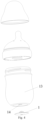
- Fig 1 is a schematic view of the structure of the air-return valve
- Fig 2 is a cross-sectional view of the air-return valve along the length direction of the valve lip portion
- Fig 3 is a cross-sectional view of the air-return valve along the direction perpendicular to the length direction of the valve lip portion
- Fig 4 a schematic view of the connection of the air-return container.
- Fig 2 is a schematic view at the design period, and there is some interference.
- the air-return valve will deform at the interference since it is capable of elastic deformation, and thus there is no interference in practical use.
- an air-return valve 1 is provided, which is used to be mounted on a container to return air and compensate for the negative pressure in the container.
- the air-return valve 1 includes a valve body and an air path formed along the axial direction of the valve body (the direction of the axis of the valve body).
- the valve body includes a valve lip portion 3 and a valve body portion.
- the valve lip portion 3 is located above the valve body portion.
- the air path passes through the valve body portion.
- the valve lip portion 3 is provided with an air gap 2 connected to the air path. The air gap 2 is closed when the interior of the container is under non-negative pressure.
- Non-negative pressure means that the pressure in the container is not less than the atmospheric pressure, and it may be the status that the pressure at the air-return valve 1 is larger than the atmospheric pressure, e.g., the air-return valve 1 is immersed in the liquid in the container and the total pressure of the liquid and gas within the container at the air-return valve 1 is larger than the atmospheric pressure.
- the pressure at the air-return valve 1 is equal to the atmospheric pressure, e.g., (1) the air-return valve 1 is immersed in the liquid in the container and the total pressure of the liquid and gas within the container at the air-return valve 1 is equal to the atmospheric pressure (at this time, the pressure of the gas within the container is less than the atmospheric pressure, but the part of it which is less than the atmospheric pressure is just compensated by the pressure of the liquid), and (2) the air-return valve 1 does not contact the liquid in the container and the gas pressure within the container is equal to the atmospheric pressure.
- the valve body portion when the air-return valve 1 is mounted on the container, the valve body portion is fitted with the container wall, and the valve lip portion 3 is positioned in the container.
- the external gas enters into the container after the air gap 2 is opened by the external gas which pass through the air path.
- the air gap 2 When not returning air, the air gap 2 is at a natural state (closed state), with function of unidirectional guide and communication.
- the valve lip portion is a boss enclosed with the diaphragm, and is raised above the valve body portion and subjected to the concentrated pressure, which can ensure the reliability of the seal and prevent the liquid leakage from the air gap 2.
- the wall thickness of the valve lip portion 3 is smaller than that of the valve body portion, so that the action of the valve lip portion is sensitive and reliable when returning air and sealing.
- the outer contour area of the valve lip portion 3 is smaller than that of the valve body portion, which can effectively reduce the volume ratio of the valve lip portion 3 to the valve body portion, thereby reducing the possibility of liquid leakage at the air gap 2.
- the outer contour area of the valve lip portion 3 is 1/15 to 1/5 of that of the valve body portion, and most preferably is 1/10, which enables the valve lip portion 3 easy to act and prevent liquid leakage.
- a lower concave surface 8 is provided on the top surface of the valve body portion, and the valve lip portion 3 is positioned on the lower concave surface 8.
- the lower concave surface 8 rises smoothly until it reaches and is connected with the top surface of the valve body portion.
- the valve lip portion 3 is immersed in liquid, the lower concave surface 8 is subjected to the pressure from the periphery toward the center, and then tends to gather downward, so as to exert a force on the valve lip portion 3, thereby making the air gap 2 on the valve lip portion 3 to be closed more tightly, ensuring that no liquid leakage occurs at the air gap 2.
- the wall thickness of the top surface of the valve body portion is reduced at the lower concave surface 8.
- the lower concave surface 8 When the lower concave surface 8 is subjected to the liquid pressure, it tends to sink, which would exert a force gathering from the periphery toward the center on the valve lip portion 3, ensuring the reliability of the closure of the air gap 2.
- the interface of the valve lip portion 3 and the lower concave surface 8 is the first edge 15.
- the first edge 15 is in a closed ring shape, which facilitates the valve body portion to transmit the force to the valve lip portion 3. It is noted that, in this embodiment, for the convenient manufacturing of the product, the first edge 15 may also be rounded, and the radius of the rounded corner is extremely small, such as 0.1mm, 0.2mm, etc., without departing from the scope of the embodiment.
- the air gap 2 is in a straight linear shape, which is convenient for closing and opening.
- the air gap 2 is opened at the top of the valve lip portion 3 and is positioned on the symmetric plane of the valve lip portion 3, so that the forces on both sides of the air gap 2 could be balanced.
- the valve body portion includes a valve head and a valve neck 5, and the valve neck 5 is positioned below the valve head.
- the valve head is used to carry the valve lip portion 3, and the valve neck 5 is used to fit into the mounting hole 14 on the container wall.
- the outer contour area of the valve head is larger than that of the valve neck 5 when projected along the axial direction of the valve body, so that the valve neck 5 can be squeezed into the mounting hole 14 and the valve head can cover the top of the mounting hole 14 to prevent liquid leakage therefrom.
- a first rounded corner 6 is provided at the outer peripheral edge of the top of the valve head, which is convenient for plugging the air-return valve 1 into the mounting hole 14 for easy operation.
- a support body 10 is also included.
- the support body 10 is in the form of cylindrical shape and is used to support the valve neck 5. It provides a supporting function without hindering the gas flow of the air path.
- the axis of the support body 10 coincides with the axis of the valve neck 5, and can provide uniform support force for the valve neck 5 in the circumferential direction.
- the support body 10 may be made of plastic material, such as PPSU (Polyphenylene Sulfone resins), which provides a supporting function on the inner wall of the valve body.
- the support body 10 may also be made of rubber material, which is the same as that of the valve body.
- the valve body may be made of rubber material, such as silicone material, which is easy to elastically deform. When being mounded at the mounting hole 14, it can be squeezed between the support body 10 and the mounting hole 14 to avoid leakage.
- the support body 10 is integrally formed with the valve body, and they are single component in structure and cannot be detached, which can reduce the number of components and facilitate carrying and storage.
- the air-return valve 1 When in use, the air-return valve 1 can be connected to the mounting hole 14 by snapping connection, threading connection, etc., and can be removed from the container for easy cleaning and assembly.
- the design of the support body 10 can provide a supporting function and improve the anti-deformation ability of the valve body, so as to expediently mount the air-return valve 1 on the mounting hole 14; when the air-return valve 1 is mounted on the mounting hole 14, the support body 10 can squeeze the valve body between the support body 10 and the mounting hole 14, thereby ensuring the air-return valve 1 being reliably on the mounting hole 14, avoiding the liquid leakage and an accidental detachment of the air-return valve 1.
- the support body 10 is wrapped inside the valve neck 5, the outer diameter of the support body 10 is smaller than that of the valve neck 5, and the inner diameter of the support body 10 is larger than the diameter of the air path.
- the rubber encapsulation design is adopted, and the support body 10 is used as a bracket inside the valve neck 5 to support the valve neck 5.
- the support body 10 is positioned in the air path, and the support body 10 fits with the valve neck 5 at the outer peripheral surface.
- the outer diameter of the support body 10 is larger than the diameter of the air inlet 11 of the air path.
- the fitting area between the support body 10 and the valve body is increased, and the support body 10 is restricted by the valve body at both ends in the axial direction, and thus the axial displacement would not occur.
- the support body 10 will not be separated from the valve body.
- the inner diameter of the support body 10 is not larger than the diameter of the air inlet 11 of the air path, and may be smaller than the diameter of the air inlet 11 of the air path, or may be equal to the diameter of the air inlet 11 of the air path, which is convenient for cleaning.
- the support body 10 is positioned in the air path, and the support body 10 is a thickened ring.
- the inner diameter of the support body 10 is not larger than the diameter of the air inlet of the air path.
- the support body 10 is made of the same material as the valve body, and they are the single component in structure. As a part of the valve body used for thickening, it can improve the ability of the valve body to resist deformation in the radial direction.
- the support body 10 may also be made of the same material as the valve body and is separated from the valve body, that is, they are two components in structure.
- the valve body also includes a valve disc 7, and the valve disc 7 is positioned below the valve neck 5.
- the outer contour area of the valve disc 7 is larger than that of the valve neck 5 when projected along the axial direction of the valve body.
- the valve disc 7 can be stuck at the bottom of the mounting hole 14 to prevent liquid leakage and prevent the air-return valve 1 from falling into the container through the mounting hole 14.
- the top surface of the valve disc 7 is an arc-shaped surface, in which the edge height is higher than the center height.
- the valve disc 7 is gradually upturned from the center to the edge, and can be sucked onto the outer wall of the container when in use.
- the bottom surface of the valve disc 7 is an arc-shaped surface, and the edge height is higher than the center height.
- the valve disc 7 is gradually upturned from the center to the edge, which can prevent the valve disc 7 from being sucked on the plane on which the container is placed, and when the top surface of the valve disc 7 is sucked onto the outer wall of the container (the shape of the outer wall tends to a plane), the bottom surface of the valve disc 7 is synchronously deformed and tends to the plane, and the container is not easy to be tipped when placed.
- the periphery of the top surface of the valve disc 7 is provided with a second edge 16, and the periphery of the bottom surface of the valve disc 7 is provided with a fourth rounded corner 12.
- the valve neck 5 is provided with a second rounded corner 9.
- the second rounded corner 9 can be fitted with the inner edge of the mounting hole 14 on the container wall and press onto the inner edge of the mounting hole 14 to ensure the reliability of the seal.
- the valve neck 5 is provided with a third rounded corner 4.
- the third rounded corner 4 can be fitted with the outer edge of the mounting hole 14 on the container wall and press onto the outer edge of the mounting hole 14 to further ensure the reliability of the seal.
- valve body portion and the valve lip portion 3 are both cylinders.
- the outer contour of the valve body portion is circular, which could reduce costs.
- the outer contour of the valve lip portion 3 is in form of oblong (oblong refers to a shape formed by replacing the two wide sides of a rectangle with two semicircles), which can be better fitted with the air gap 2, making the actions bringing the air gap 2 to return air and close more accurate.
- the outer contour of the valve lip portion 3 gradually decreases along the direction from the valve body portion to the valve lip portion 3.
- the valve lip portion 3 is subjected to an oblique downward pressure at the periphery, which can force the air gap 2 to close, thereby ensuring that there is no leakage at the air gap 2.
- the wall thickness of the valve lip portion 3 gradually decreases and reaches a minimum value at the air gap 2, which facilitates the opening and closing of the air gap 2 and makes the action more sensitive.
- valve lip portion 3 is positioned on the symmetric plane of the valve body portion, and the air gap 2 is positioned on the symmetric plane of the valve lip portion 3 along the length direction, which has the advantage that the forces are balanced and the action would be accurate during use, as well as the production costs would be reduced.
- the present invention also provides an air-return container 13.
- the air-return container 13 includes a container body and an air-return valve 1.
- a mounting hole 14 is provided on the container body, and the air-return valve 1 is interference-fitted with the mounting hole 14.
- the air-return valve 1 can return air into the air-return container 13 to compensate for the negative pressure in the air-return container 13, so as to facilitate the user to ingest the liquid in the air-return container 13.
- the mounting hole 14 may be positioned on the side wall of the container body, or on the top of the container body, or on the bottom of the container body.
- the air-return valve 1 is mounted at the mounting hole 14, which functions as unidirectional guide and communication, which can not only compensate for the negative pressure in the air-return container 13, but also prevent the liquid in the air-return container 13 from leakage.
- the air-return valve 1 communicates with the air in the air-return container 13 when compensating for the negative pressure in the air-return container 13.
- the air entering the air-return container 13 through the air-return valve 1 would not pass through the milk, and thus would not mix with the milk. This can not only prevent the infant from flatulence due to inhalation of bubbles in the milk when feeding, but also prevent the milk from being oxidized due to mixing with bubbles.
- the mounting hole 14 is positioned at the bottom of the container body, and the bottom of the container body is provided with an inwardly concave surface.
- the air-return valve can effectively return air when the bottom of the container body is facing upward or the bottom is facing obliquely upward, e.g., when that is applied to a feeding bottle, the milk will not be oxidized, and the infant will not ingest bubbles.
- the outer contour area of the valve disc 7 of the air-return valve 1 is smaller than the area of the inwardly concave surface of the container body, and will not affect the stability of the container body when it is placed.
- the working process of the present invention is described in detail by the example that it is applied to a milk bottle as following:
- the container body is a bottle body.
- a nipple is mounted on the bottle body, and a dust cover is mounted on the nipple.
- a mounting hole 14 is provided at the bottom of the bottle body, and an air-return valve 1 is mounted on the mounting hole 14.
- the support body 10 When the milk bottle is placed on a plane, the support body 10 is supported in the valve body; the valve head covers above the mounting hole 14; the valve neck 5 and the mounting hole 14 are interference-fitted, which ensures the reliability of the seal.
- the valve neck 5 is provided with a second rounded corner 9 and a third rounded corner 4, and two additional defense lines are provided on the basis of the interference-fit, which further ensures that the sealing meets the use requirements.
- the valve lip portion 3 and the valve head of the air-return valve 1 are positioned below the liquid surface and are immersed in the liquid.
- the liquid gives a downward pressure to the top surface of the valve head, so that the bottom surface of the valve head tends to sink downward, which would exert a force gathering from the periphery toward the center on the valve lip portion 3, ensuring the closure of the air gap 2 and preventing leakage.
- the liquid also exert an oblique downward force to the valve lip portion 3 at the periphery, which further ensures the reliability of the closure of the air gap 2.
- the air-return valve 1 When feeding with the milk bottle, the bottom of the milk bottle is upward or tilted upward, and the air-return valve 1 is separated from the milk. When the air pressure in the milk bottle decreases, the air-return valve 1 can return air in time to ensure smooth feeding.
- the air-return valve 1 communicates with the air in the milk bottle when compensating for the negative pressure in the bottle body. The air entering the milk bottle through the air-return valve 1 would not pass through the milk, so that it would not mix with the milk. That can not only prevent the baby from flatulence due to inhaling bubbles in the milk when feeding, but also prevent the milk from being oxidized due to mixing with bubbles.
Landscapes
- Engineering & Computer Science (AREA)
- General Engineering & Computer Science (AREA)
- Health & Medical Sciences (AREA)
- Life Sciences & Earth Sciences (AREA)
- Animal Behavior & Ethology (AREA)
- General Health & Medical Sciences (AREA)
- Public Health (AREA)
- Veterinary Medicine (AREA)
- Mechanical Engineering (AREA)
- Closures For Containers (AREA)
Applications Claiming Priority (3)
| Application Number | Priority Date | Filing Date | Title |
|---|---|---|---|
| CN202221875116.6U CN217815172U (zh) | 2022-07-12 | 2022-07-12 | 一种回气阀和回气容器 |
| CN202210820869.5A CN115355343A (zh) | 2022-07-12 | 2022-07-12 | 一种回气阀和回气容器 |
| PCT/CN2023/103298 WO2023232153A1 (zh) | 2022-07-12 | 2023-06-28 | 一种回气阀和回气容器 |
Publications (1)
| Publication Number | Publication Date |
|---|---|
| EP4556768A1 true EP4556768A1 (de) | 2025-05-21 |
Family
ID=89025728
Family Applications (1)
| Application Number | Title | Priority Date | Filing Date |
|---|---|---|---|
| EP23815329.0A Pending EP4556768A1 (de) | 2022-07-12 | 2023-06-28 | Rückschlagventil und luftrückschlagbehälter |
Country Status (3)
| Country | Link |
|---|---|
| US (1) | US20250387302A1 (de) |
| EP (1) | EP4556768A1 (de) |
| WO (1) | WO2023232153A1 (de) |
Family Cites Families (8)
| Publication number | Priority date | Publication date | Assignee | Title |
|---|---|---|---|---|
| EP3104827B1 (de) * | 2014-02-16 | 2021-04-07 | T.T.Y. General Trade Lines Ltd. | Belüfteter flüssigkeitsbehälter |
| CN104224553B (zh) * | 2014-08-20 | 2016-07-20 | 林四海 | 奶瓶进气阀 |
| CN204170116U (zh) * | 2014-09-30 | 2015-02-25 | 陈金良 | 一种新型防胀气奶瓶 |
| CN204275054U (zh) * | 2014-11-10 | 2015-04-22 | 刘荣 | 一种奶瓶 |
| CN108814986A (zh) * | 2018-05-21 | 2018-11-16 | 黄银坤 | 婴儿奶瓶 |
| IL275502A (en) * | 2020-06-18 | 2022-01-01 | Agaloo Ltd | Air intake system |
| CN217815172U (zh) * | 2022-07-12 | 2022-11-15 | 北京申创世纪信息技术有限公司 | 一种回气阀和回气容器 |
| CN115355343A (zh) * | 2022-07-12 | 2022-11-18 | 北京申创世纪信息技术有限公司 | 一种回气阀和回气容器 |
-
2023
- 2023-06-28 EP EP23815329.0A patent/EP4556768A1/de active Pending
- 2023-06-28 WO PCT/CN2023/103298 patent/WO2023232153A1/zh not_active Ceased
- 2023-06-28 US US18/879,768 patent/US20250387302A1/en active Pending
Also Published As
| Publication number | Publication date |
|---|---|
| US20250387302A1 (en) | 2025-12-25 |
| WO2023232153A1 (zh) | 2023-12-07 |
Similar Documents
| Publication | Publication Date | Title |
|---|---|---|
| CN1972660B (zh) | 奶瓶 | |
| GB2477185A (en) | Nursing bottle with an opening at each end and an inlet valve in the base | |
| US20160346168A1 (en) | Nursing bottle having air returning function | |
| EP4556768A1 (de) | Rückschlagventil und luftrückschlagbehälter | |
| CN201168222Y (zh) | 奶瓶漂浮进气防胀气装置 | |
| CN217815172U (zh) | 一种回气阀和回气容器 | |
| CN115355343A (zh) | 一种回气阀和回气容器 | |
| CN215884724U (zh) | 一种瓶盖及水瓶 | |
| CN111824589B (zh) | 一种防伪瓶盖 | |
| RU2859280C2 (ru) | Клапан возврата воздуха и емкость с клапаном возврата воздуха | |
| CN217937814U (zh) | 一种吸管式水杯 | |
| CN221932702U (zh) | 一种吸奶器 | |
| CN208611363U (zh) | 奶瓶及液体盛装器具 | |
| CN218961433U (zh) | 一种穿戴式吸奶器 | |
| CN218739560U (zh) | 防胀气两用奶瓶 | |
| CN222942685U (zh) | 瓶口通气连接件及饮水装置 | |
| CN223716055U (zh) | 一种多角度回气的奶嘴 | |
| CN209033207U (zh) | 奶瓶盖及包括该奶瓶盖的奶瓶 | |
| CN108186363A (zh) | 一种吮吸更省力的宽口奶瓶 | |
| CN209751698U (zh) | 高密封性奶嘴组件 | |
| CN207532564U (zh) | 一种防止倒吸空气的奶/水瓶吸管阀门 | |
| CN2204599Y (zh) | 气芯式防呛奶瓶 | |
| CN223490105U (zh) | 一种奶嘴及奶瓶 | |
| CN223459967U (zh) | 一种回气阀 | |
| CN219250985U (zh) | 利乐包转接十字接口 |
Legal Events
| Date | Code | Title | Description |
|---|---|---|---|
| STAA | Information on the status of an ep patent application or granted ep patent |
Free format text: STATUS: THE INTERNATIONAL PUBLICATION HAS BEEN MADE |
|
| PUAI | Public reference made under article 153(3) epc to a published international application that has entered the european phase |
Free format text: ORIGINAL CODE: 0009012 |
|
| STAA | Information on the status of an ep patent application or granted ep patent |
Free format text: STATUS: REQUEST FOR EXAMINATION WAS MADE |
|
| 17P | Request for examination filed |
Effective date: 20241227 |
|
| AK | Designated contracting states |
Kind code of ref document: A1 Designated state(s): AL AT BE BG CH CY CZ DE DK EE ES FI FR GB GR HR HU IE IS IT LI LT LU LV MC ME MK MT NL NO PL PT RO RS SE SI SK SM TR |
|
| DAV | Request for validation of the european patent (deleted) | ||
| DAX | Request for extension of the european patent (deleted) |