EP4556771A2 - Dispositif de soupape à vide et système comprenant une pompe à vide et un dispositif de soupape à vide - Google Patents
Dispositif de soupape à vide et système comprenant une pompe à vide et un dispositif de soupape à vide Download PDFInfo
- Publication number
- EP4556771A2 EP4556771A2 EP25166623.6A EP25166623A EP4556771A2 EP 4556771 A2 EP4556771 A2 EP 4556771A2 EP 25166623 A EP25166623 A EP 25166623A EP 4556771 A2 EP4556771 A2 EP 4556771A2
- Authority
- EP
- European Patent Office
- Prior art keywords
- vacuum
- valve device
- gas
- channel
- pressure measuring
- Prior art date
- Legal status (The legal status is an assumption and is not a legal conclusion. Google has not performed a legal analysis and makes no representation as to the accuracy of the status listed.)
- Pending
Links
Images

Classifications
-
- F—MECHANICAL ENGINEERING; LIGHTING; HEATING; WEAPONS; BLASTING
- F16—ENGINEERING ELEMENTS AND UNITS; GENERAL MEASURES FOR PRODUCING AND MAINTAINING EFFECTIVE FUNCTIONING OF MACHINES OR INSTALLATIONS; THERMAL INSULATION IN GENERAL
- F16K—VALVES; TAPS; COCKS; ACTUATING-FLOATS; DEVICES FOR VENTING OR AERATING
- F16K37/00—Special means in or on valves or other cut-off apparatus for indicating or recording operation thereof, or for enabling an alarm to be given
- F16K37/0025—Electrical or magnetic means
- F16K37/005—Electrical or magnetic means for measuring fluid parameters
-
- F—MECHANICAL ENGINEERING; LIGHTING; HEATING; WEAPONS; BLASTING
- F04—POSITIVE - DISPLACEMENT MACHINES FOR LIQUIDS; PUMPS FOR LIQUIDS OR ELASTIC FLUIDS
- F04D—NON-POSITIVE-DISPLACEMENT PUMPS
- F04D19/00—Axial-flow pumps
- F04D19/02—Multi-stage pumps
- F04D19/04—Multi-stage pumps specially adapted to the production of a high vacuum, e.g. molecular pumps
- F04D19/042—Turbomolecular vacuum pumps
-
- F—MECHANICAL ENGINEERING; LIGHTING; HEATING; WEAPONS; BLASTING
- F04—POSITIVE - DISPLACEMENT MACHINES FOR LIQUIDS; PUMPS FOR LIQUIDS OR ELASTIC FLUIDS
- F04B—POSITIVE-DISPLACEMENT MACHINES FOR LIQUIDS; PUMPS
- F04B37/00—Pumps having pertinent characteristics not provided for in, or of interest apart from, groups F04B25/00 - F04B35/00
- F04B37/10—Pumps having pertinent characteristics not provided for in, or of interest apart from, groups F04B25/00 - F04B35/00 for special use
- F04B37/14—Pumps having pertinent characteristics not provided for in, or of interest apart from, groups F04B25/00 - F04B35/00 for special use to obtain high vacuum
-
- F—MECHANICAL ENGINEERING; LIGHTING; HEATING; WEAPONS; BLASTING
- F04—POSITIVE - DISPLACEMENT MACHINES FOR LIQUIDS; PUMPS FOR LIQUIDS OR ELASTIC FLUIDS
- F04B—POSITIVE-DISPLACEMENT MACHINES FOR LIQUIDS; PUMPS
- F04B39/00—Component parts, details, or accessories, of pumps or pumping systems specially adapted for elastic fluids, not otherwise provided for in, or of interest apart from, groups F04B25/00 - F04B37/00
- F04B39/10—Adaptations or arrangements of distribution members
-
- F—MECHANICAL ENGINEERING; LIGHTING; HEATING; WEAPONS; BLASTING
- F04—POSITIVE - DISPLACEMENT MACHINES FOR LIQUIDS; PUMPS FOR LIQUIDS OR ELASTIC FLUIDS
- F04B—POSITIVE-DISPLACEMENT MACHINES FOR LIQUIDS; PUMPS
- F04B49/00—Control, e.g. of pump delivery, or pump pressure of, or safety measures for, machines, pumps, or pumping installations, not otherwise provided for, or of interest apart from, groups F04B1/00 - F04B47/00
- F04B49/22—Control, e.g. of pump delivery, or pump pressure of, or safety measures for, machines, pumps, or pumping installations, not otherwise provided for, or of interest apart from, groups F04B1/00 - F04B47/00 by means of valves
-
- F—MECHANICAL ENGINEERING; LIGHTING; HEATING; WEAPONS; BLASTING
- F04—POSITIVE - DISPLACEMENT MACHINES FOR LIQUIDS; PUMPS FOR LIQUIDS OR ELASTIC FLUIDS
- F04B—POSITIVE-DISPLACEMENT MACHINES FOR LIQUIDS; PUMPS
- F04B51/00—Testing machines, pumps, or pumping installations
-
- F—MECHANICAL ENGINEERING; LIGHTING; HEATING; WEAPONS; BLASTING
- F04—POSITIVE - DISPLACEMENT MACHINES FOR LIQUIDS; PUMPS FOR LIQUIDS OR ELASTIC FLUIDS
- F04D—NON-POSITIVE-DISPLACEMENT PUMPS
- F04D27/00—Control, e.g. regulation, of pumps, pumping installations or pumping systems specially adapted for elastic fluids
- F04D27/001—Testing thereof; Determination or simulation of flow characteristics; Stall or surge detection, e.g. condition monitoring
-
- F—MECHANICAL ENGINEERING; LIGHTING; HEATING; WEAPONS; BLASTING
- F04—POSITIVE - DISPLACEMENT MACHINES FOR LIQUIDS; PUMPS FOR LIQUIDS OR ELASTIC FLUIDS
- F04D—NON-POSITIVE-DISPLACEMENT PUMPS
- F04D29/00—Details, component parts, or accessories
- F04D29/002—Details, component parts, or accessories especially adapted for elastic fluid pumps
-
- F—MECHANICAL ENGINEERING; LIGHTING; HEATING; WEAPONS; BLASTING
- F16—ENGINEERING ELEMENTS AND UNITS; GENERAL MEASURES FOR PRODUCING AND MAINTAINING EFFECTIVE FUNCTIONING OF MACHINES OR INSTALLATIONS; THERMAL INSULATION IN GENERAL
- F16K—VALVES; TAPS; COCKS; ACTUATING-FLOATS; DEVICES FOR VENTING OR AERATING
- F16K27/00—Construction of housing; Use of materials therefor
- F16K27/02—Construction of housing; Use of materials therefor of lift valves
- F16K27/029—Electromagnetically actuated valves
-
- F—MECHANICAL ENGINEERING; LIGHTING; HEATING; WEAPONS; BLASTING
- F16—ENGINEERING ELEMENTS AND UNITS; GENERAL MEASURES FOR PRODUCING AND MAINTAINING EFFECTIVE FUNCTIONING OF MACHINES OR INSTALLATIONS; THERMAL INSULATION IN GENERAL
- F16K—VALVES; TAPS; COCKS; ACTUATING-FLOATS; DEVICES FOR VENTING OR AERATING
- F16K31/00—Actuating devices; Operating means; Releasing devices
- F16K31/02—Actuating devices; Operating means; Releasing devices electric; magnetic
- F16K31/06—Actuating devices; Operating means; Releasing devices electric; magnetic using a magnet, e.g. diaphragm valves, cutting off by means of a liquid
- F16K31/0644—One-way valve
- F16K31/0655—Lift valves
-
- F—MECHANICAL ENGINEERING; LIGHTING; HEATING; WEAPONS; BLASTING
- F16—ENGINEERING ELEMENTS AND UNITS; GENERAL MEASURES FOR PRODUCING AND MAINTAINING EFFECTIVE FUNCTIONING OF MACHINES OR INSTALLATIONS; THERMAL INSULATION IN GENERAL
- F16K—VALVES; TAPS; COCKS; ACTUATING-FLOATS; DEVICES FOR VENTING OR AERATING
- F16K51/00—Other details not peculiar to particular types of valves or cut-off apparatus
- F16K51/02—Other details not peculiar to particular types of valves or cut-off apparatus specially adapted for high-vacuum installations
Definitions
- the present invention relates to a vacuum valve device that can be installed in a vacuum system.
- vacuum systems which usually comprise one or more recipients that can be evacuated by vacuum pumps, so that the corresponding processing or process steps can then be carried out in them.
- vacuum pumps are provided with suitable performance characteristics.
- Vacuum systems also include valve devices with which the individual components of the vacuum system can be separated from one another and/or from the environment.
- sensors are usually provided that can measure the pressure prevailing at suitable points within the system.
- the data from these sensors can be processed by a control unit and serve as the basis for appropriate control of at least one vacuum pump and/or the valve device(s).
- the object of the present invention is to provide a vacuum valve device which enables monitoring and control of a vacuum system in a cost-effective manner.
- the vacuum valve device comprises a valve housing having a gas inlet and a gas outlet.
- the gas inlet and the gas outlet are connected to each other by a through-channel.
- the through-channel can be selectively closed in a gas-tight manner by a movably arranged valve body that interacts with a valve seat in a closed position.
- at least one gas pressure sensor integrated into the valve device is provided, with which a gas pressure prevailing in a section of the through-channel assigned to it can be determined.
- the gas inlet and gas outlet can be connected to other components of a vacuum system, for example, directly to a vacuum chamber and/or a gas outlet of a vacuum pump and/or to vacuum lines.
- the gas pressure sensor can be used to determine the pressure prevailing in the passageway when the valve is open. When the valve is closed, with the valve body sealingly interacting with the valve seat, the gas pressure sensor can measure the pressure in the section of the passageway assigned to it.
- a gas pressure sensor By integrating a gas pressure sensor into the vacuum valve device, a compact component is created that measures the gas pressure at a central component of a vacuum system. With the installation of the vacuum valve device, two functionalities are integrated into the corresponding vacuum system (shut-off option and monitoring sensor), which Installation costs and times are significantly reduced. Furthermore, it is not necessary to provide special line sections with corresponding adapters to integrate gas pressure sensors into the vacuum system. Integrating pressure sensors into vacuum pumps is associated with considerable costs and makes maintenance and/or repair work complex.
- the gas pressure sensor is arranged in a pressure measuring chamber formed in the valve housing, which is in fluid communication with the through-channel.
- the chamber can be dimensioned as needed to accommodate a pressure sensor that meets the respective requirements.
- the pressure measuring chamber can be connected to the through-channel via a pressure measuring channel, with the pressure measuring channel having a smaller opening cross-section than the pressure measuring chamber.
- This design takes into account the fact that even a small opening cross-section is sufficient to enable pressure equalization between the pressure measuring chamber and the through-channel.
- the pressure measuring channel can also have an opening cross-section of the same size or even larger.
- a cover element can be provided, by which the pressure measuring chamber is sealed gas-tight from the environment.
- the cover element can be accommodated, at least in sections, in a recess arranged in an outer side of the valve housing and from which the pressure measuring chamber extends into the interior of the valve housing.
- the thickness of the cover element can be at least partially compensated by the recess in order to
- the vacuum valve device is designed to be as compact as possible. It also facilitates assembly.
- the gas pressure sensor is arranged on a circuit board that forms the cover element.
- a connection device for electronically connecting the gas pressure sensor can be provided on a side of the circuit board facing away from the gas sensor.
- the circuit board can function as a vacuum feedthrough, which, on the one hand, seals the pressure measuring chamber gas-tight and, on the other hand, enables the output of the data measured by the gas pressure sensor.
- valve body is arranged to be linearly movable.
- the direction of movement of the valve body can be perpendicular to a respective longitudinal extension of the pressure measuring chamber and/or at least a portion of the through-channel.
- the vacuum valve device can comprise an actuator device with which the valve body can be moved to open and/or close the passage.
- a single cable can be used to simultaneously control the actuator device and connect the gas pressure sensor.
- the vacuum valve device comprises, in addition to the gas pressure sensor, at least one second gas pressure sensor which is integrated into the valve device.
- the gas pressure sensor described above can be arranged such that a gas pressure sensor in the passageway between The first gas pressure prevailing between the gas inlet and the valve seat can be determined.
- the second gas pressure sensor is then arranged such that a second gas pressure prevailing in the passageway between the gas outlet and the valve seat can be determined.
- this embodiment can also monitor a flow rate through the vacuum valve device.
- the second pressure measuring channel can have a smaller opening cross-section than the second pressure measuring chamber.
- the second pressure measuring chamber can also be sealed off from the environment by a cover element.
- This cover element can be designed separately from the cover element for the first pressure measuring chamber.
- a common cover element is preferably provided that seals off the first and second pressure measuring chambers.
- this cover element is a circuit board that accommodates the first gas pressure sensor and the second gas pressure sensor. While it is conceivable in principle to provide a separate connection device for each gas pressure sensor, it is particularly cost-effective and compact if a common connection device is assigned to the two gas pressure sensors.
- the invention further relates to a system comprising at least one vacuum pump and at least one separate vacuum valve device detachably attached to the vacuum pump or connected thereto according to at least one of the embodiments described above.
- a direct connection Connecting the valve assembly to the vacuum pump results in a particularly compact design.
- the vacuum pump is a high-vacuum pump (e.g., a turbomolecular pump)
- a backing pump is usually provided to ensure that the high-vacuum pump's outlet has an already reduced pressure against which it can work.
- the valve device according to the invention now provides two functionalities: In addition to a pure blocking effect, it can be used to monitor the system, namely by determining the inlet-side pressure, i.e., the backing pressure. If this pressure deviates from the expected pressure (e.g., it is too high), the valve device can be closed to protect the high-vacuum pump.
- a particularly advantageous embodiment of the vacuum valve device with two gas pressure sensors is in this context, since, for example, when the valve device is closed, it can be checked whether the pressure difference on both sides of a valve body in the closed position is so small that the valve device can be opened safely.
- the gas pressure sensor and/or - if present - the actuator device of the vacuum valve device are connected to a control device for controlling the system.
- the control device can be a control unit of the vacuum pump or be integrated therein.
- the control device is a higher-level control unit or is integrated into one that is provided for controlling a vacuum system.
- Such vacuum systems can be very complex and comprise several recipients, pumps and comprise a plurality of valve lines which can advantageously be controlled centrally.
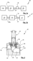
- Fig. 1 shows a vacuum system 10 comprising a recipient 12, a high-vacuum pump 14, for example, a turbomolecular pump, and a backing pump 16 of any design.
- a valve device 18 (hereinafter also referred to as a valve) is provided between the pumps 14, 16 to separate the pumps 14, 16 from each other if necessary.
- the valve 18 is arranged in a pipeline 20 that connects the pumps 14, 16.
- the high-vacuum pump 14 is connected to the recipient 12 via a pipeline 20a.
- valve 18 is a component arranged separately from the pumps 14, 16. It is connected to a control device (not shown), which in turn may be connected to other components (not shown), for example, various sensors and/or other valves, pumps, or recipients.
- Fig. 1b shows a vacuum system 10'.
- the valve 18 is arranged directly in the area of an outlet of the high vacuum pump and is detachably attached to it, thereby achieving a particularly compact design.
- vacuum systems 10, 10' described above are merely exemplary of systems with at least one vacuum pump and a valve according to the invention.
- Fig. 2 shows the valve 18 in a cross-section. It comprises a valve housing 22 with an inlet 24 and an outlet 26. A bore 28 and 30, respectively, extend from the inlet 24 and the outlet 26 into the interior of the valve housing 22. The bores 28, 30 run parallel and offset from one another.
- the bore 28 is connected to a bore 32 arranged at right angles thereto, the end of which facing away from the bore 28 forms a valve seat 34.
- a valve body 38 In the closed state of the valve 18 shown, a valve body 38 is pressed against the valve seat by the action of a spring 36, thereby blocking fluid communication between the inlet 24 and the outlet 26.
- an actuator device 39 (not shown in detail but well known in the art) is actuated, pulling the valve body 38 upward against the action of the spring 36.
- the actuator device 39 can be actuated, for example, pneumatically, electrically, or electromagnetically (e.g., by a selectively energizable coil).
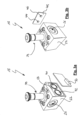
- FIG. 3a and 3b show perspective views of the valve 18, which has two pressure measuring chambers 40, 42, which are connected to the bores 28 and 30, respectively.
- Gas pressure sensors 44, 46 are arranged in the pressure measuring chambers 40, 42. which are arranged on a common cover element 48, with which the pressure measuring chambers are sealed gas-tight from the environment and from each other.
- the cover element 48 is designed as a gas-tight circuit board, which carries a connection element 50 on its outer surface, which is connected to the sensors 44, 46.
- the connection element 50 can comprise a plug device to which a cable can be attached, so that the data from the sensors 44, 46 can be fed to a control device.
- This control device (not shown) can also be provided for actuating the actuator device 39 and/or controlling other components of the vacuum system.
- FIG. 4a and 4c Sections through the valve 18 are shown (namely sections BB and CC), the respective positions of which are marked in a side view of the valve 18 (cf. Fig. 4b ).
- Fig. 4a shows a section through the pressure measuring chamber 40. It is connected to the bore 28 via a pressure measuring channel 52.
- the pressure measuring channel 52 is also a bore, but its diameter is significantly smaller than that of the chamber 40.
- the sensor 44 can therefore measure the pressure prevailing in the bore 28.
- the sensor 44 is arranged on a circuit board 48, which seals the pressure measuring chamber 40 from the outside.
- the circuit board 48 is partially accommodated by a recess 54, which is also in Fig. 3a can be clearly seen.
- a seal 56 is provided between the circuit board 48 and the recess.
- Fig. 4c shows a section through the pressure measuring chamber 42, into which the sensor 46 arranged on the common circuit board 48 protrudes.
- the pressure measuring chamber 42 is connected to the bore 30 via a pressure measuring channel 58. Since the bore 30
- the pressure measuring channel 58 is arranged parallel to the bore 28 and is inclined. It is also a bore in the present embodiment.
- the chambers 40, 42 are arranged parallel and at the same height in the valve housing 22. They extend perpendicularly to both the bores 28, 30 and the bore 32.
- valve 18 can be easily manufactured from a monolithic workpiece by drilling a number of holes. This results in a design that is both robust and compact. However, it is understood that the valve housing 22 can also be constructed in multiple pieces.
Landscapes
- Engineering & Computer Science (AREA)
- General Engineering & Computer Science (AREA)
- Mechanical Engineering (AREA)
- Physics & Mathematics (AREA)
- Electromagnetism (AREA)
- Valve Housings (AREA)
- Compressors, Vaccum Pumps And Other Relevant Systems (AREA)
- Indication Of The Valve Opening Or Closing Status (AREA)
- Details Of Valves (AREA)
- Structures Of Non-Positive Displacement Pumps (AREA)
- Non-Positive Displacement Air Blowers (AREA)
Priority Applications (3)
| Application Number | Priority Date | Filing Date | Title |
|---|---|---|---|
| EP25166623.6A EP4556771A3 (fr) | 2024-04-25 | 2025-03-27 | Dispositif de soupape à vide et système comprenant une pompe à vide et un dispositif de soupape à vide |
| JP2025070272A JP2025168297A (ja) | 2024-04-25 | 2025-04-22 | 真空バルブ装置、および、真空ポンプと真空バルブ装置とを備えるシステム |
| CN202510530112.6A CN120845359A (zh) | 2024-04-25 | 2025-04-25 | 真空阀装置及包含真空泵与真空阀装置的系统 |
Applications Claiming Priority (2)
| Application Number | Priority Date | Filing Date | Title |
|---|---|---|---|
| US18/645,475 US20250334202A1 (en) | 2024-04-25 | 2024-04-25 | Vacuum valve |
| EP25166623.6A EP4556771A3 (fr) | 2024-04-25 | 2025-03-27 | Dispositif de soupape à vide et système comprenant une pompe à vide et un dispositif de soupape à vide |
Publications (2)
| Publication Number | Publication Date |
|---|---|
| EP4556771A2 true EP4556771A2 (fr) | 2025-05-21 |
| EP4556771A3 EP4556771A3 (fr) | 2025-10-22 |
Family
ID=95338128
Family Applications (1)
| Application Number | Title | Priority Date | Filing Date |
|---|---|---|---|
| EP25166623.6A Pending EP4556771A3 (fr) | 2024-04-25 | 2025-03-27 | Dispositif de soupape à vide et système comprenant une pompe à vide et un dispositif de soupape à vide |
Country Status (3)
| Country | Link |
|---|---|
| EP (1) | EP4556771A3 (fr) |
| JP (1) | JP2025168297A (fr) |
| CN (1) | CN120845359A (fr) |
Family Cites Families (8)
| Publication number | Priority date | Publication date | Assignee | Title |
|---|---|---|---|---|
| DE10022124B4 (de) * | 2000-05-06 | 2010-01-14 | Wabco Gmbh | Elektronisches Steuergerät |
| KR200435917Y1 (ko) * | 2006-09-29 | 2007-03-15 | 한국콘트롤공업 주식회사 | 가스압검출기를 가진 전자밸브 |
| US8844561B2 (en) * | 2010-05-20 | 2014-09-30 | Eaton Corporation | Isolation valve with integrated sensor |
| JP2014159779A (ja) * | 2013-02-20 | 2014-09-04 | Kyoshin Engineering:Kk | 真空排気ユニット及び真空制御方法 |
| DE102016100501B3 (de) * | 2016-01-13 | 2017-04-06 | Pierburg Gmbh | Sekundärluftventil für einen Verbrennungsmotor |
| KR20220133817A (ko) * | 2021-03-25 | 2022-10-05 | (주)제이티 | 공압제어모듈 및 그를 가지는 소자핸들러 |
| KR102687881B1 (ko) * | 2022-07-28 | 2024-07-25 | 고병혁 | 센서 일체형 압력 제어용 진공 밸브 및 이를 구비하는 진공 시스템 |
| DE102023101130B4 (de) * | 2023-01-18 | 2025-03-27 | J.Schmalz Gmbh | Ventilvorrichtung und Unterdruckhandhabungsvorrichtung mit Ventilvorrichtung |
-
2025
- 2025-03-27 EP EP25166623.6A patent/EP4556771A3/fr active Pending
- 2025-04-22 JP JP2025070272A patent/JP2025168297A/ja active Pending
- 2025-04-25 CN CN202510530112.6A patent/CN120845359A/zh active Pending
Also Published As
| Publication number | Publication date |
|---|---|
| JP2025168297A (ja) | 2025-11-07 |
| EP4556771A3 (fr) | 2025-10-22 |
| CN120845359A (zh) | 2025-10-28 |
Similar Documents
| Publication | Publication Date | Title |
|---|---|---|
| DE60223341T2 (de) | Direkt angetriebenes Pneumatikventil mit luftunterstütztem Rückhub | |
| EP3082406B1 (fr) | Vanne de sécurité | |
| DE102016206821A1 (de) | Verfahren zum Betreiben einer Ventileinrichtung, Ventileinrichtung und Datenträger mit einem Computerprogramm | |
| DE69621291T2 (de) | Fluid-Regelungssystem sowie dafür verwendetes Ventil | |
| DE102012002921A1 (de) | Servoventil | |
| DE69715751T2 (de) | An ein mehrstufiges Umschaltventil angeflanschter Druckregler | |
| EP0145858A2 (fr) | Ensemble de clapet magnétique | |
| DE4404224A1 (de) | Hydraulische Funktionseinheit | |
| DE102018200680B4 (de) | Drucküberwachungsvorrichtung und damit ausgestattete Ventilanordnung | |
| DE3601643A1 (de) | Hydraulische steuervorrichtung fuer den schnellgang von verbrauchern | |
| EP4556771A2 (fr) | Dispositif de soupape à vide et système comprenant une pompe à vide et un dispositif de soupape à vide | |
| DE202006020516U1 (de) | Regeleinrichtung für einen druckmittelbetriebenen Stellantrieb | |
| DE19829530A1 (de) | Ventilanordnung | |
| DE10046977A1 (de) | Elektromagnetisch betätigbare Ventileinrichtung und Ventilvorrichtung | |
| DE3147030C2 (de) | Magnetventileinheit | |
| DE4435339C2 (de) | Anordnung zur Ansteuerung eines hydraulisch betätigbaren Hauptventils | |
| EP0102443A1 (fr) | Tiroir à voies multiples | |
| DE7834499U1 (de) | Servobetaetigtes dreiwegeventil | |
| DE3741425C2 (fr) | ||
| DE3836300C2 (de) | Magnetventil | |
| DE10006141A1 (de) | Elektrohydraulische Steuervorrichtung | |
| DE102004044770B3 (de) | Druckregelventil mit umschaltbaren Arbeitsanschlüssen | |
| EP1510699B1 (fr) | Procédé et dispositif pour commuter un flux | |
| EP2606981B1 (fr) | Module de changement de teinte et changeur de teinte | |
| WO1997012150A1 (fr) | Distributeur a actionnement electromagnetique |
Legal Events
| Date | Code | Title | Description |
|---|---|---|---|
| PUAI | Public reference made under article 153(3) epc to a published international application that has entered the european phase |
Free format text: ORIGINAL CODE: 0009012 |
|
| STAA | Information on the status of an ep patent application or granted ep patent |
Free format text: STATUS: THE APPLICATION HAS BEEN PUBLISHED |
|
| AK | Designated contracting states |
Kind code of ref document: A2 Designated state(s): AL AT BE BG CH CY CZ DE DK EE ES FI FR GB GR HR HU IE IS IT LI LT LU LV MC ME MK MT NL NO PL PT RO RS SE SI SK SM TR |
|
| PUAL | Search report despatched |
Free format text: ORIGINAL CODE: 0009013 |
|
| AK | Designated contracting states |
Kind code of ref document: A3 Designated state(s): AL AT BE BG CH CY CZ DE DK EE ES FI FR GB GR HR HU IE IS IT LI LT LU LV MC ME MK MT NL NO PL PT RO RS SE SI SK SM TR |
|
| RIC1 | Information provided on ipc code assigned before grant |
Ipc: F16K 51/02 20060101AFI20250918BHEP Ipc: F16K 27/02 20060101ALI20250918BHEP Ipc: F16K 31/06 20060101ALI20250918BHEP Ipc: F16K 37/00 20060101ALI20250918BHEP |
|
| STAA | Information on the status of an ep patent application or granted ep patent |
Free format text: STATUS: REQUEST FOR EXAMINATION WAS MADE |