EP4556791A1 - Drahtlos betriebene wasserdichte schienenleuchte - Google Patents
Drahtlos betriebene wasserdichte schienenleuchte Download PDFInfo
- Publication number
- EP4556791A1 EP4556791A1 EP23210546.0A EP23210546A EP4556791A1 EP 4556791 A1 EP4556791 A1 EP 4556791A1 EP 23210546 A EP23210546 A EP 23210546A EP 4556791 A1 EP4556791 A1 EP 4556791A1
- Authority
- EP
- European Patent Office
- Prior art keywords
- lamp
- track
- power supply
- wireless
- magnets
- Prior art date
- Legal status (The legal status is an assumption and is not a legal conclusion. Google has not performed a legal analysis and makes no representation as to the accuracy of the status listed.)
- Pending
Links
Images




Classifications
-
- F—MECHANICAL ENGINEERING; LIGHTING; HEATING; WEAPONS; BLASTING
- F21—LIGHTING
- F21V—FUNCTIONAL FEATURES OR DETAILS OF LIGHTING DEVICES OR SYSTEMS THEREOF; STRUCTURAL COMBINATIONS OF LIGHTING DEVICES WITH OTHER ARTICLES, NOT OTHERWISE PROVIDED FOR
- F21V21/00—Supporting, suspending, or attaching arrangements for lighting devices; Hand grips
- F21V21/34—Supporting elements displaceable along a guiding element
- F21V21/35—Supporting elements displaceable along a guiding element with direct electrical contact between the supporting element and electric conductors running along the guiding element
-
- F—MECHANICAL ENGINEERING; LIGHTING; HEATING; WEAPONS; BLASTING
- F21—LIGHTING
- F21V—FUNCTIONAL FEATURES OR DETAILS OF LIGHTING DEVICES OR SYSTEMS THEREOF; STRUCTURAL COMBINATIONS OF LIGHTING DEVICES WITH OTHER ARTICLES, NOT OTHERWISE PROVIDED FOR
- F21V21/00—Supporting, suspending, or attaching arrangements for lighting devices; Hand grips
- F21V21/08—Devices for easy attachment to any desired place, e.g. clip, clamp, magnet
- F21V21/096—Magnetic devices
-
- H—ELECTRICITY
- H01—ELECTRIC ELEMENTS
- H01F—MAGNETS; INDUCTANCES; TRANSFORMERS; SELECTION OF MATERIALS FOR THEIR MAGNETIC PROPERTIES
- H01F38/00—Adaptations of transformers or inductances for specific applications or functions
- H01F38/14—Inductive couplings
-
- H—ELECTRICITY
- H01—ELECTRIC ELEMENTS
- H01F—MAGNETS; INDUCTANCES; TRANSFORMERS; SELECTION OF MATERIALS FOR THEIR MAGNETIC PROPERTIES
- H01F7/00—Magnets
- H01F7/02—Permanent magnets [PM]
- H01F7/0231—Magnetic circuits with PM for power or force generation
- H01F7/0247—Orientating, locating, transporting arrangements
-
- H—ELECTRICITY
- H02—GENERATION; CONVERSION OR DISTRIBUTION OF ELECTRIC POWER
- H02J—ELECTRIC POWER NETWORKS; CIRCUIT ARRANGEMENTS OR SYSTEMS FOR SUPPLYING OR DISTRIBUTING ELECTRIC POWER; SYSTEMS FOR STORING ELECTRIC ENERGY
- H02J50/00—Circuit arrangements or systems for wireless supply or distribution of electric power
- H02J50/10—Circuit arrangements or systems for wireless supply or distribution of electric power using inductive coupling
-
- F—MECHANICAL ENGINEERING; LIGHTING; HEATING; WEAPONS; BLASTING
- F21—LIGHTING
- F21V—FUNCTIONAL FEATURES OR DETAILS OF LIGHTING DEVICES OR SYSTEMS THEREOF; STRUCTURAL COMBINATIONS OF LIGHTING DEVICES WITH OTHER ARTICLES, NOT OTHERWISE PROVIDED FOR
- F21V21/00—Supporting, suspending, or attaching arrangements for lighting devices; Hand grips
- F21V21/14—Adjustable mountings
- F21V21/30—Pivoted housings or frames
-
- F—MECHANICAL ENGINEERING; LIGHTING; HEATING; WEAPONS; BLASTING
- F21—LIGHTING
- F21V—FUNCTIONAL FEATURES OR DETAILS OF LIGHTING DEVICES OR SYSTEMS THEREOF; STRUCTURAL COMBINATIONS OF LIGHTING DEVICES WITH OTHER ARTICLES, NOT OTHERWISE PROVIDED FOR
- F21V23/00—Arrangement of electric circuit elements in or on lighting devices
- F21V23/04—Arrangement of electric circuit elements in or on lighting devices the elements being switches
- F21V23/0442—Arrangement of electric circuit elements in or on lighting devices the elements being switches activated by means of a sensor, e.g. motion or photodetectors
- F21V23/0471—Arrangement of electric circuit elements in or on lighting devices the elements being switches activated by means of a sensor, e.g. motion or photodetectors the sensor detecting the proximity, the presence or the movement of an object or a person
Definitions
- the present invention relates to the technical field of track lights, and in particular, to a wireless powered waterproof track light.
- the current track light structure is shown in the publication number WO2018157567A1 and Taiwan Patent Announcement M619216 . It is usually implemented with a track for fixing to the wall or ceiling.
- the bottom surface of the track is formed with an opening connected to its interior, and two conductive strips are provided in the track.
- the two conductive sheets are connected to the transformer through electrical wires.
- a lamp is provided with a sliding seat, and the sliding seat is provided with conductive terminals for contacting the two conductive strips.
- the sliding seat of the lamp is installed under the opening of the track, so that the two conductive terminals of the sliding seat are in contact with the two conductive strips for power supply. Therefore, the lamp can be installed at any position on the track, and power can be supplied to the lamp at any position on the track.
- the tracks of conventional track lights have a structure with openings on the bottom, which makes it easy for water and moisture to invade. Therefore, conventional track lights can only be installed indoors and cannot be used outdoors or even in water. If the track of the track light is to be implemented as a closed structure to prevent the intrusion of water and moisture, there will be a problem that the conductive terminals of the external lamps cannot contact the two conductive strips in the track.
- conventional track lights require the use of complex mechanical assembly structures, such as latches, sliders, fixing screws and other components, in order to install the lights on the track. Therefore, its manufacturing cost is high, and the actual installation and adjustment are very inconvenient. For example, multiple fixing screws need to be loosened to move the lamp on the track.
- the main object of the present invention is to provide a wireless powered waterproof track light, which achieves the function of wireless power supply through one or more wireless power supply transmitting modules provided in the power supply track and a wireless power supply receiving module provided in the lamp. And through magnet adsorption technology, the lamps can be adsorbed on the power supply track at will.
- a secondary object of the present invention is to provide a wireless powered waterproof track light.
- the power supply track can be implemented into a closed track, so that the wireless power supply transmitting module will not be exposed to rainwater in the power supply track, and the wireless powered waterproof track light can be used as an outdoor waterproof track light.
- the preferred technical solution of the wireless powered waterproof track light of the present invention consists of a power supply track, a wireless power supply transmitting module and a lamp.
- the power supply track comprises a track body and two conductive strips.
- the outer surface of the track body has a lamp mounting surface, and the interior of the track body has a closed sliding space corresponding to the lamp mounting surface.
- the two conductive strips are arranged in the closed sliding space and extend parallel to the lamp mounting surface to supply power to the wireless power supply transmitting module.
- the wireless power supply transmitting module comprises a slide, a transmitting coil, two conductive terminals and two first magnets.
- the slide is set in the closed sliding space of the d track body to move arbitrarily within the closed sliding space.
- the transmitting coil is arranged on the slide to generate a magnetic field in the closed sliding space toward the lamp mounting surface.
- the two conductive terminals are fixed on the slide and connected to the transmitting coil.
- the two conductive terminals removably contact the two conductive strips.
- the first magnets are fixed on the slide to adsorb each other with the lamp.
- the lamp comprises a lamp body, a receiving coil and two second magnets.
- the lamp body is detachably set on the lamp mounting surface of the track body and movable on the lamp mounting surface.
- the receiving coil is set in the lamp body to sense the magnetic field of the transmitting coil to generate an induced current and supply power to the lamp body.
- the second magnets is fixed on the lamp body and is used to attract the first magnets magnetically, so that the lamp body is detachably adsorbed on the lamp mounting surface.
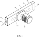
- the present invention shows a wireless powered waterproof track light, which is a waterproof track light that can be installed on a wall or ceiling and can move and adjust the lamp position arbitrarily.
- the preferred embodiment comprises a power supply track 10, a wireless power supply transmitting module 20 and a lamp 30. Install the wireless power supply transmitting module 20 into the power supply track 10 so that the wireless power supply transmitting module 20 supplies power to the lamp 30 adsorbed on the power supply track 10 through wireless charging technology.
- the power supply track 10 preferably comprises a track body 11 and two conductive strips 12.
- the outer surface of the track body 11 has a lamp mounting surface 111, and the interior of the track body 11 has a closed sliding space 112 corresponding to the lamp mounting surface 111.
- the two conductive strips 12 are arranged in the closed sliding space 112 and extend parallel to the lamp mounting surface 111 to supply power to the wireless power supply transmitting module 20.
- the track body 11 is preferably implemented with a tube body 13, two end caps 14 and a power cord 15.
- the tube body 13 can be an aluminum extruded straight rectangular tube or an arc rectangular tube. A plane outside the rectangular tube is used as the lamp mounting surface 111 for one or more lamps 30 to be magnetically attached to the lamp mounting surface 111.
- the inside of the rectangular tube serves as the above-mentioned closed sliding space 112, and two strip-shaped mounting grooves 131 can be provided on the inner wall of the tube body 13, and the two conductive strips 12 are fixed in the two strip-shaped mounting grooves 131.
- the two end caps 14 hermetically cover the two opposite ends of the tube body 13 respectively to prevent water and moisture from entering the closed sliding space 112.
- One end of the power cord 15 passes through the wall of one end cap 14 or tube body 13, enters the closed sliding space 112 and is connected to the two conductive strips 12, and the other end is connected to a power supply (such as a transformer, etc.).
- the above-mentioned conductive strips 12 are preferably copper strips.
- One side of each of the conductive strips 12 is combined with an insulator 16, so that each conductive strip 12 or the insulator 16 is fixed in one respective strip-shaped mounting groove 131, and can be used to power the wireless power supply transmitting module 20.
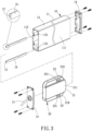
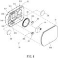
- the wireless power supply transmitting module 20 preferably comprises a slide 21, a transmitting coil 22, two conductive terminals 23, two first magnets 24 and a magnetic switch 25.
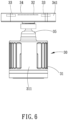
- the slide 21 is set in the closed sliding space 112 of the track body 11, and its position can be moved arbitrarily in the closed sliding space 112.
- the transmitting coil 22 is a copper coil wound into a ring and is arranged on the slide 21 to generate a magnetic field in the closed sliding space 112 toward the lamp mounting surface 111.
- the two conductive terminals 23 are components stamped from copper sheets. They are respectively fixed on the slide 21 and connected to the transmitting coil 22, so that the two conductive terminals 23 contact the two conductive strips 12 and move together with the slide 21 (as shown in FIG.
- the first magnets 24 are permanent magnets fixed on the slide 21 and are mutually attracted to the lamp 30 outside the track body 11.
- the magnetic switch 25 is an existing electronic component and is connected in the circuit of the transmitting coil 22. When the lamp 30 is adsorbed on the lamp mounting surface 111, the magnetic switch 25 forms a path through the magnetism of a third magnet 36 of the lamp 30, and then energizes the transmitting coil 22. On the contrary, when the lamp 30 is detached, the magnetic switch 25 forms an open circuit, and its transmitting coil 22 will no longer consume power.
- the configuration of the slide 21 is not limited, and is preferably implemented as a first housing 211 and a first cover 212.
- the first housing 211 has a plurality of mounting grooves 214, 215, 216, and 217 inside for the mounting of the transmitting coil 22, the two conductive terminals 23, the first magnets 24, and the magnetic switch 25.
- This forms a modular component, which facilitates the installation of multiple wireless power supply transmitting modules 20 in the track body 11.
- the first housing 211 has two openings 218 that communicate the mounting grooves 215 for the two conductive terminals 23 with the outside of the first housing 211.
- the above-mentioned conductive terminals 23 are respectively provided with a conductive elastic piece 231.
- each conductive terminal 23 When each conductive terminal 23 is fixed on the respective mounting groove 215, the conductive elastic pieces 231 protrudes outside the first housing 211 through the openings 218 (as shown in FIG. 3 ), so that the conductive elastic pieces 231 can movably contact the respective conductive strips 12, and the slide 21 (first housing 211) can provide power to the transmitting coil 22 when the track body 11 moves to any position (as shown in FIG. 5 ).
- the lamp 30 is preferably implemented with a lamp body 31, a receiving coil 32, two second magnets 33 and a wireless power receiving module 34.
- the lamp body 31 is an existing LED lamp. In the present invention, it is used to be detachably arranged on the lamp mounting surface 111 of the track body 11, and its position can be moved on the lamp mounting surface 111.
- the receiving coil 32 and the above-mentioned transmitting coil 22 are both copper coils wound into a ring. They can be arranged in the wireless power receiving module 34 at the rear end of the lamp body 31 or directly installed inside the rear end of the lamp body 31.
- the receiving coil 32 When the receiving coil 32 is close to the transmitting coil 22, the receiving coil 32 can induce the magnetic field of the transmitting coil 22 to generate an induced current, which supplies power to the lamp body 31.
- the second magnets 33 is fixed in the wireless power receiving module 34 of the lamp body 31 or directly installed inside the rear end of the lamp body 31. It is used to adsorb to the first magnets 24 of the wireless power supply transmitting module 20 through its magnetic properties, so that the lamp body 31 can be detachably adsorbed on the lamp mounting surface 111.
- the above-mentioned wireless power receiving module 34 comprises a second housing 341 and a second cover 342.
- the second housing 341 or second cover 342 is coupled to the rear end or one side of the lamp body 31 through a direction adjustment structure 35, and then the receiving coil 32 and the second magnet 33 are respectively fixed in the second housing 341, so that the wireless power receiving module 34 is attracted to the above-mentioned first magnets 24 through the second magnets 33, and then the lamp body 31 is detachably adsorbed on the lamp mounting surface 111 of the track body 11 and the adsorption position can be moved and adjusted.
- the direction adjustment structure 35 can be an existing universal joint, so that the lamp body 31 can adjust the angle of illumination. Referring to FIG.
- the present invention does not need to implement the above-mentioned second housing 341 and second cover 342, but directly fixes the receiving coil 32 and the second magnets 33 inside the lamp housing 311 at the rear end of the lamp body 31, which can also achieve the same effect of attracting the first magnets 24.
- the wireless power receiving module 34 (second housing 341) or the lamp housing 311 of the lamp body 31 of the present invention is additionally provided with a rectifier circuit board 37 inside.
- the rectifier circuit board 37 is connected between the receiving coil 32 and the light-emitting unit of the lamp body 31 to provide electric energy to the lamp body 31.
- the power supply track 10 can be fixed on a wall, ceiling or other objects.
- Each power supply track 10 is preset with a plurality of wireless power supply transmitting modules 20.
- the second magnets 33 can attract the first magnets 24 of the wireless power supply transmitting module 20, and the lamp 30 can be fixed on the lamp mounting surface 111, and the lamp 30 can also be moved to cause the wireless power supply transmitting module 20 to move together in the closed sliding space 112.
- the present invention uses wireless power supply technology to eliminate the open structure technology of conventional track light lamps that need to use conductive terminals to contact two conductive strips, so that the track body 11 can be implemented as a tube body with both ends closed, and the lamp 30 can also be implemented into a fully sealed structure, thereby achieving the function of the track light being waterproof and installed outdoors.
Landscapes
- Engineering & Computer Science (AREA)
- Power Engineering (AREA)
- General Engineering & Computer Science (AREA)
- Physics & Mathematics (AREA)
- Electromagnetism (AREA)
- Computer Networks & Wireless Communication (AREA)
- Arrangement Of Elements, Cooling, Sealing, Or The Like Of Lighting Devices (AREA)
Priority Applications (1)
| Application Number | Priority Date | Filing Date | Title |
|---|---|---|---|
| EP23210546.0A EP4556791A1 (de) | 2023-11-17 | 2023-11-17 | Drahtlos betriebene wasserdichte schienenleuchte |
Applications Claiming Priority (1)
| Application Number | Priority Date | Filing Date | Title |
|---|---|---|---|
| EP23210546.0A EP4556791A1 (de) | 2023-11-17 | 2023-11-17 | Drahtlos betriebene wasserdichte schienenleuchte |
Publications (1)
| Publication Number | Publication Date |
|---|---|
| EP4556791A1 true EP4556791A1 (de) | 2025-05-21 |
Family
ID=88839362
Family Applications (1)
| Application Number | Title | Priority Date | Filing Date |
|---|---|---|---|
| EP23210546.0A Pending EP4556791A1 (de) | 2023-11-17 | 2023-11-17 | Drahtlos betriebene wasserdichte schienenleuchte |
Country Status (1)
| Country | Link |
|---|---|
| EP (1) | EP4556791A1 (de) |
Citations (8)
| Publication number | Priority date | Publication date | Assignee | Title |
|---|---|---|---|---|
| WO2016030686A1 (en) * | 2014-08-29 | 2016-03-03 | Sal London Limited | Lighting device |
| WO2018157567A1 (zh) | 2017-03-01 | 2018-09-07 | 珠海世大照明有限公司 | 轨道灯和轨道组件 |
| CN109855057A (zh) * | 2018-12-30 | 2019-06-07 | 苏州天为幕烟花科技有限公司 | 一种灯具照明式无线电源供电座 |
| DE102018116649A1 (de) * | 2018-07-10 | 2020-01-16 | Wago Verwaltungsgesellschaft Mbh | Lichtbandsystem |
| TWM619216U (zh) | 2021-07-22 | 2021-11-01 | 亮明家照明實業有限公司 | 軌道燈之組設結構 |
| EP3952002A1 (de) * | 2019-03-28 | 2022-02-09 | Aoi Japan Co., Ltd. | System zur drahtlosen stromspeisung mit batteriemontierter vorrichtung, die mit einer stromempfangenden vorrichtung mit montierter lichteinheit eingerastet ist |
| WO2022125459A1 (en) * | 2020-12-11 | 2022-06-16 | Universal City Studios Llc | Surface-mounted vehicle having a rail coupling system |
| CN218582971U (zh) * | 2022-10-21 | 2023-03-07 | 东莞市锐森灯饰有限公司 | 一种便于调节的挂壁灯 |
-
2023
- 2023-11-17 EP EP23210546.0A patent/EP4556791A1/de active Pending
Patent Citations (8)
| Publication number | Priority date | Publication date | Assignee | Title |
|---|---|---|---|---|
| WO2016030686A1 (en) * | 2014-08-29 | 2016-03-03 | Sal London Limited | Lighting device |
| WO2018157567A1 (zh) | 2017-03-01 | 2018-09-07 | 珠海世大照明有限公司 | 轨道灯和轨道组件 |
| DE102018116649A1 (de) * | 2018-07-10 | 2020-01-16 | Wago Verwaltungsgesellschaft Mbh | Lichtbandsystem |
| CN109855057A (zh) * | 2018-12-30 | 2019-06-07 | 苏州天为幕烟花科技有限公司 | 一种灯具照明式无线电源供电座 |
| EP3952002A1 (de) * | 2019-03-28 | 2022-02-09 | Aoi Japan Co., Ltd. | System zur drahtlosen stromspeisung mit batteriemontierter vorrichtung, die mit einer stromempfangenden vorrichtung mit montierter lichteinheit eingerastet ist |
| WO2022125459A1 (en) * | 2020-12-11 | 2022-06-16 | Universal City Studios Llc | Surface-mounted vehicle having a rail coupling system |
| TWM619216U (zh) | 2021-07-22 | 2021-11-01 | 亮明家照明實業有限公司 | 軌道燈之組設結構 |
| CN218582971U (zh) * | 2022-10-21 | 2023-03-07 | 东莞市锐森灯饰有限公司 | 一种便于调节的挂壁灯 |
Similar Documents
| Publication | Publication Date | Title |
|---|---|---|
| US6499859B2 (en) | Portable lighting lamp with light-emitting diodes | |
| CN217485885U (zh) | 适配器、轨道及电气系统 | |
| US7575337B2 (en) | Lamp structure | |
| US20080068830A1 (en) | Wall, headboard or ceiling mounted cordless illuminating device | |
| US20250155111A1 (en) | Wireless powered waterproof track light | |
| US10520180B1 (en) | Lamp | |
| CN210069778U (zh) | 一种磁吸轨道连接件、安装结构及灯具 | |
| TWI838325B (zh) | 無線供電防水軌道燈 | |
| US12352395B1 (en) | Lamp holder and magnetic lighting device | |
| CN209782563U (zh) | 一种滑动连接件、滑动结构及灯具 | |
| CN220822119U (zh) | 可移动式取电扩展件轻薄磁吸轨道连接结构及智能家具 | |
| JP7610230B1 (ja) | ワイヤレス電源防水トラックライト | |
| CN219222265U (zh) | 磁吸式感应模组、照明模组和照明灯具 | |
| CN119914842A (zh) | 无线供电防水轨道灯 | |
| CN220209464U (zh) | 灯具连接器及照明系统 | |
| WO2021088961A1 (zh) | 磁吸导电轨道、转接器、电气装置及电气系统 | |
| RU2023944C1 (ru) | Переносной настольный светильник | |
| CN217482598U (zh) | 一种灯体及磁吸轨道灯具 | |
| CN117329489A (zh) | 一种球头柱塞式磁吸轨道灯 | |
| CN214332617U (zh) | 一种灯具高/低压通用轨道安装模块 | |
| CN220383264U (zh) | 具有磁吸固定功能的灯具控制器 | |
| CN105870749A (zh) | 转接头、照明装置 | |
| CN220582338U (zh) | 便携式照明设备 | |
| TWM599371U (zh) | 燈具結構 | |
| KR101606633B1 (ko) | 엘이디 조명등의 전기 접속장치 |
Legal Events
| Date | Code | Title | Description |
|---|---|---|---|
| PUAI | Public reference made under article 153(3) epc to a published international application that has entered the european phase |
Free format text: ORIGINAL CODE: 0009012 |
|
| STAA | Information on the status of an ep patent application or granted ep patent |
Free format text: STATUS: REQUEST FOR EXAMINATION WAS MADE |
|
| 17P | Request for examination filed |
Effective date: 20250320 |
|
| AK | Designated contracting states |
Kind code of ref document: A1 Designated state(s): AL AT BE BG CH CY CZ DE DK EE ES FI FR GB GR HR HU IE IS IT LI LT LU LV MC ME MK MT NL NO PL PT RO RS SE SI SK SM TR |