EP4556811A1 - Solarenergiesystem mit einem konzentrator mit faltbarer struktur - Google Patents
Solarenergiesystem mit einem konzentrator mit faltbarer struktur Download PDFInfo
- Publication number
- EP4556811A1 EP4556811A1 EP23209653.7A EP23209653A EP4556811A1 EP 4556811 A1 EP4556811 A1 EP 4556811A1 EP 23209653 A EP23209653 A EP 23209653A EP 4556811 A1 EP4556811 A1 EP 4556811A1
- Authority
- EP
- European Patent Office
- Prior art keywords
- concentrator
- main body
- energy
- stabilizing
- state
- Prior art date
- Legal status (The legal status is an assumption and is not a legal conclusion. Google has not performed a legal analysis and makes no representation as to the accuracy of the status listed.)
- Withdrawn
Links
Images




Classifications
-
- F—MECHANICAL ENGINEERING; LIGHTING; HEATING; WEAPONS; BLASTING
- F24—HEATING; RANGES; VENTILATING
- F24S—SOLAR HEAT COLLECTORS; SOLAR HEAT SYSTEMS
- F24S20/00—Solar heat collectors specially adapted for particular uses or environments
- F24S20/80—Airborne solar heat collector modules, e.g. inflatable structures
-
- B—PERFORMING OPERATIONS; TRANSPORTING
- B64—AIRCRAFT; AVIATION; COSMONAUTICS
- B64G—COSMONAUTICS; VEHICLES OR EQUIPMENT THEREFOR
- B64G1/00—Cosmonautic vehicles
- B64G1/22—Parts of, or equipment specially adapted for fitting in or to, cosmonautic vehicles
- B64G1/222—Parts of, or equipment specially adapted for fitting in or to, cosmonautic vehicles for deploying structures between a stowed and deployed state
- B64G1/2221—Parts of, or equipment specially adapted for fitting in or to, cosmonautic vehicles for deploying structures between a stowed and deployed state characterised by the manner of deployment
- B64G1/2227—Inflating
-
- B—PERFORMING OPERATIONS; TRANSPORTING
- B64—AIRCRAFT; AVIATION; COSMONAUTICS
- B64G—COSMONAUTICS; VEHICLES OR EQUIPMENT THEREFOR
- B64G1/00—Cosmonautic vehicles
- B64G1/22—Parts of, or equipment specially adapted for fitting in or to, cosmonautic vehicles
- B64G1/42—Arrangements or adaptations of power supply systems
- B64G1/428—Power distribution and management
- B64G1/4282—Power distribution and management for transmitting power to earth or other spacecraft
-
- F—MECHANICAL ENGINEERING; LIGHTING; HEATING; WEAPONS; BLASTING
- F24—HEATING; RANGES; VENTILATING
- F24S—SOLAR HEAT COLLECTORS; SOLAR HEAT SYSTEMS
- F24S20/00—Solar heat collectors specially adapted for particular uses or environments
- F24S20/50—Rollable or foldable solar heat collector modules
- F24S20/55—Rollable or foldable solar heat collector modules made of flexible materials
-
- F—MECHANICAL ENGINEERING; LIGHTING; HEATING; WEAPONS; BLASTING
- F24—HEATING; RANGES; VENTILATING
- F24S—SOLAR HEAT COLLECTORS; SOLAR HEAT SYSTEMS
- F24S23/00—Arrangements for concentrating solar-rays for solar heat collectors
- F24S23/30—Arrangements for concentrating solar-rays for solar heat collectors with lenses
-
- F—MECHANICAL ENGINEERING; LIGHTING; HEATING; WEAPONS; BLASTING
- F24—HEATING; RANGES; VENTILATING
- F24S—SOLAR HEAT COLLECTORS; SOLAR HEAT SYSTEMS
- F24S23/00—Arrangements for concentrating solar-rays for solar heat collectors
- F24S23/70—Arrangements for concentrating solar-rays for solar heat collectors with reflectors
- F24S23/71—Arrangements for concentrating solar-rays for solar heat collectors with reflectors with parabolic reflective surfaces
-
- Y—GENERAL TAGGING OF NEW TECHNOLOGICAL DEVELOPMENTS; GENERAL TAGGING OF CROSS-SECTIONAL TECHNOLOGIES SPANNING OVER SEVERAL SECTIONS OF THE IPC; TECHNICAL SUBJECTS COVERED BY FORMER USPC CROSS-REFERENCE ART COLLECTIONS [XRACs] AND DIGESTS
- Y02—TECHNOLOGIES OR APPLICATIONS FOR MITIGATION OR ADAPTATION AGAINST CLIMATE CHANGE
- Y02E—REDUCTION OF GREENHOUSE GAS [GHG] EMISSIONS, RELATED TO ENERGY GENERATION, TRANSMISSION OR DISTRIBUTION
- Y02E10/00—Energy generation through renewable energy sources
- Y02E10/40—Solar thermal energy, e.g. solar towers
- Y02E10/47—Mountings or tracking
Definitions
- the present invention relates to a device for harvesting solar energy comprising a main body comprising at least one concentrator for solar energy and heat energy and a controlling means at least for controlling the concentrator, a solar energy system comprising at least one device for harvesting solar energy and thermal energy and a method of harvesting solar energy using a main body and a concentrator of the device and system.
- Transporting small solar arrays from a manufacturing site to a final solar array location requires either a high volume of transport over land and water, or a significant design effort for assembly at the manufacturer's site, trial operation at the manufacturer's site, disassembly at the manufacturer's site, logistics, shipping, transport, unloading, and finally reassembly at the intended site.
- These complex and complicated relationships apart from being associated with high costs and time, can easily lead to technical problems, such as assembly errors, and can have a detrimental effect on the functionality of the solar system, at least temporarily.
- III-V multi-junction solar cells for space in the state of the art. These are lighter in weight but have high manufacturing costs and larger housings that are required for transport to space but are therefore disadvantageous for this transport. In addition, these PV panels with III-V multi-junction solar cells generally have an efficiency of less than 40% and do not convert heat or infrared radiation.
- the object of the present invention is therefore to provide a device, a system and a method with which solar energy can be harvested in a constructively simple manner not only in space, but especially there.
- the object is solved in that the concentrator has a foldable structure with a volume that is smaller in a first folded state than in a second unfolded state, the controlling means is configurated to control the transfer from the first folded state to the second unfolded state.
- the object is also solved by a solar energy system comprising the device according to the invention.
- the solution according to the invention provides an unfoldable, expandable or inflatable concentrator photovoltaic (CPV) structure that can be used with space-based solar power (SBSP) for deployment on Earth and in space, e.g. on Moon, on Mars or on any other planet or in any other orbit.
- CPV photovoltaic
- SBSP space-based solar power
- parabolic concentrator system of the present invention in combination with different other systems could also be used e.g. as an optical telescope, as an antenna for telecommunication or even as an antenna for power beaming.
- the present invention lowers manufacturing and sales costs, has a lower overall weight than comparable devices of conventional design, requires only a small bounding box when launched into space, and due to its structure, has better transportability and deployment capability by unfolding , as well as an overall higher conversion efficiency compared to the state of the art in PV technology.
- the system of the present invention includes the concept of a satellite combined with a foldable device and power beaming technology, and the concept of a corresponding network of satellites.
- the foldable structure comprises a stabilizing device for stabilizing the concentrator in the second unfolded state.
- a foldable stabilizing device optimizes space requirements during transport and positioning of the device according to the invention in space but also on Earth.
- the stabilizing device comprises at least one stabilizing means, wherein the stabilizing device having an inflatable structure which is inflated in the second unfolded state.
- the stabilizing device having an inflatable structure which is inflated in the second unfolded state.
- balloon-like structures can be used for the concentrator or at least parts thereof.
- a further advantage of the present invention is that the concentrator is connected to the main body via a stabilizing device.
- the concentrator can be arranged at a predetermined distance from the main body and aligned with the main body.
- the stabilizing device comprises at least one stabilizing means, wherein the stabilizing device having a mechanically connected structure which is unfolded in the second unfolded state.
- mechanical connection and folding techniques known from space travel for example, for unfolding telescopes, can be used.
- the concentrator in the unfolded , second state is arranged with respect to the main body in such a way that a focal point of the concentrator is located in the main body, at least with a center of the focal point. This makes it possible to obtain the maximum concentration of energy in the main body and to perform the conversion into electrical energy there.
- the alignment of the concentrator and the main body is such that the focal point is located in the main body, saving conduction paths and associated energy "losses" during conversion.
- the main body comprises a device for converting photon energy and thermal energy concentrated in the focal point into electrical energy. This makes it possible to transfer the electrical energy by means of known transfer methods to another location where it can be used or further treated.
- the concentrator is formed with a rotating mass.
- a rotating mass facilitates the precise alignment and positioning of the very light parabolic concentrator at its working position.
- the rotating mass can be multipart and distributed around the circumference of the concentrator.
- a gas source is arranged in the main body and is connected to the concentrator via a valve device.
- the gas source can basically be arranged in any position, but it is advantageous if the gas source is arranged in the main body in a protected position. Then the gas source does not interfere with the concentrator inflation process.
- the concentrator can then be connected to the main body in a simple manner via the valve device and can be transferred from the uninflated, empty state to the inflated second state in response to a control signal sent by a remote controlling device, for example from a computer located anywhere on earth or in space.
- the concentrator is a lens.
- a lens concentrates the beams and focuses them on the focal point. Such a construction is very convenient for certain applications.
- the concentrator may also be advantageous for the concentrator to be a reflector.
- the choice between lens and reflector is subject to the decision of the man skilled in the art, depending also on the construction of the main body and the place of use.
- the main body comprises a transmitting device suitable for transmitting electrical energy to a receiving device, which may be located anywhere on earth or in space.
- a receiving device which may be located anywhere on earth or in space.
- the main body to be located at a great distance from the receiving device, for example in an embodiment of the main body as a space satellite, a space habitat, a space station or the like.
- This enumeration is not intended to be a limitation to the aforementioned locations. There is of course no limitation.
- the method according to the invention comprises launching the main body into a position on an orbit of the earth. This makes it possible to also use the main body in its space application, for example as a space satellite.
- the present invention shall focus the solar energy onto a focal point, using a lightweight material, e.g. carbon fiber rods or the like , in the first embodiment and lightweight, polymeric, inflatable tube structures in the second embodiment for the stabilizing structure of the concentrator, and suitable, lightweight, polymeric or textile films for the parabolic concentrator itself.
- a satellite with efficient solar technology e.g., thermo-photo-voltaic (TPV) cells, perovskite cells, high-power multi-junction cells or thin-film cells on the inventive structure combined with thermoelectric generators (TEG)
- TSV thermo-photo-voltaic
- perovskite cells perovskite cells
- TEG thermoelectric generators
- the photonic energy will be collected by coated thin-film PV cells on the foldable and alternatively also inflatable structure (lens or reflector) and the thermal energy will be collected by an energy converter in the focal point (TPV or TEG).
- TPV or TEG energy converter in the focal point
- the difference with regard to common PV cells is the collection of additional thermal energy by the use of novel thermal-to-electric energy converters without moving parts (TPV or TEG).
- Today's space solar cells' technology is able to collect about 200 W/m 2 .
- To collect 1 kW of electrical energy a 5 m 2 panel is required.
- the concentrator system of the present invention would have a diameter of about 2.5 m, corresponding to 5 m 2 .
- Considering the solar constant in space approximately 1.35 kW/m 2 , a total amount of 6.75 kW will be received by the foldable and alternatively also inflatable structure and focussed onto the focal point.
- Current TPV technology using selective emitters has an efficiency of about 40%.
- a 40 % efficiency should be reached by the combination of PV (about 30 %) and TEG (about 10%) technologies. Consequently, 2.7 kW of electricity could be generated at the focal point. This is 2.7 times more electrical energy compared to today's space solar panels.
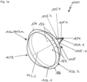
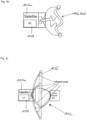
- a device 100 according to the present invention is shown schematically and in perspective.
- the device 100 comprises a main body 101 and a concentrator 102.
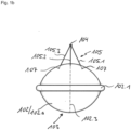
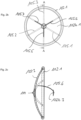
- the concentrator 102 in Fig. 1a , Fig. 1b , Fig.1 c has a stabilizing and unfoldable structure, which in Fig. 1a , Fig. 1b and Fig. 1c is in the unfolded, expanded or inflated state.
- This unfolded, expanded or inflated state is the working state or functional state of the device 100 according to the invention and will be referred to as the second state below.
- a first state will be described in more detail later under Fig. 4a .
- the concentrator 102 being unfolded and/or expanded or inflated is configured to form a lens 102a that allows solar energy and heat energy to enter on a facing side 103 directed towards the sun.
- the facing side 103 is located on a side opposite to the main body 101 and focuses solar energy and heat energy onto a focal point 104 due to the lens-shaped configuration.
- the focal point 104 is located inside the main body 101.
- the main body 101 is configured to be a satellite 101a.
- the concentrator 102 is connected to the main body 101 via a stabilizing device 105.
- the stabilizing device 105 comprises at least a first stabilizing means 105.1.
- a first stabilizing means 105.1 In the embodiment shown in Fig.1a , Fig. 1b and Fig. 1c , four stabilizing means 105.1, 105.2, 105.3 and 105.4 are provided. However, in other embodiments, two, three or more than four stabilizing means 105.1, 105.2, 105.3, 105.4 may be provided.
- the stabilizing device 105 with the at least one stabilizing means 105.1, 105.2, 105.3, 105.4 are rods which also forms the foldable structure.
- Such a mechanical structure with rods is made from lightweight materials.
- Such materials can be any materials known in lightweight construction, for example carbon or carbon-containing composites, which are hinged together.
- the inflatable tubes of the second embodiment each consist of inflatable polymeric tubes on the inner side and of a textile fabric on the outer side for maintaining the correct form, structural strength and protection.
- the concentrator 102 which is formed as a lens 102a, has a stiffening ring 102.1 which, in the second embodiment shown in Fig.1a , Fig. 1b and Fig. 1c , extends as an equator 102.2 around a rotation axis 102.3 of the lens 102a.
- a rotating mass 106 is attached to the stiffening ring 102.1 to support rotation of the lens 102a about the rotation axis 102.3.
- the rotating mass 106 also forms a connection point 107 between the support device 105 and the concentrator 102, respectively.
- one end of the at least one stabilizing means 105.1, 105.2, 105.3, 105.4 is connected at the connection point 107 to the concentrator 102 or the lens 102a in the region of the stiffening ring 102.1.
- the respective connection point 107 may also be provided at another location of the circumference of the lens 102a and also independently of the rotating mass 106.
- the device 100 according to the invention is shown in an embodiment in which the concentrator 102 is formed as a reflector 102b.
- the reflector 102b is located on a side of the main body 101 facing the sun and reflects the radiation incident on its mirror-like underside 102b.1 back to a second mirror 102b.3 and from there to the focal point 104 in the main body 101.
- the second mirror 102b.3 is held by retaining elements 105.5, 105.6 and 105.7.he reflector 102b also has a foldable structure which, has a light-reflecting inner layer 102b.2 on a side towards the incident rays. Otherwise, the construction of the device 100 in Fig. 2a , Fig. 2b and Fig. 2c is identical to that in Fig.1a , Fig. 1b and Fig. 1c .
- the concentrator 102 in the first and second embodiment shown in Fig.1a , Fig. 1b and Fig. 1c and Fig. 2a , Fig. 2b and Fig. 2c is preferably made of a lightweight polymeric material that is stretchable and expands in response to a gas pressure, making it suitable for inflating balloon-like structures. Such materials are generally known and are not the subject of the present invention.
- the concentrator 102 in Fig.1a , Fig. 1b and Fig. 1c and Fig. 2a , Fig. 2b and Fig. 2c may be made of a lightweight textile or solid material, which is a lightweight textile material that forms a parabolic textile form or a solid material that forms a hinged mechanical unit.
- the concentrator 102 is connected to a side wall 101.1 of the main body 101 and thus also of the satellite 101a.
- a gas source 108 present in the satellite 101a for example in the form of at least one gas cylinder, may be connected to the concentrator 102 via a valve device (not shown).
- at least one smaller gas cylinder may be attached to the periphery of the concentrator 102, for example to the stiffening ring 102.1
- at least one small gas cylinder is attached to the periphery of the concentrator 102, it may also form the rotating mass 106.
- the rotating mass 106 could be replaced in whole or in part by the at least one gas cylinder and accordingly could be omitted in whole or in part.
- the device of the present invention may be inflated by a gas tank / supply on the satellite, the gas inlet would be through a backplate connection, leading the gas into the inflatable tubes.
- the device might have smaller gas bottles with gas nozzles on the inflatable circumference, which can additionally be used for setting the system into spinning motion for stabilization.
- the backplate at the back/center of the inflatable structure enables spinning of the inflatable structure and may be connected to the main body or satellite by screws or the like.
- the inflatable structure might be covered inside the bounding box 110 for protection, which opens in space just before inflation.
- thermo-photo-voltaic cells TPV
- perovskite cells high power multi-junction cells or thin film cells
- TOG thermoelectric generator
- This solar technology which is known per se, is summarized in the following under the term conversion device 109.
- the conversion device 109 and thus also the focal point 104 are arranged in the main body 101 in Fig.1a , Fig. 1b and Fig. 1c and Fig. 2a , Fig. 2b and Fig. 2c respectively.
- the main body 101 is a satellite 101a.
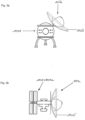
- the main body 101 may be formed for other applications in space and on Earth. Some non-exhaustive examples of this are shown schematically in Fig. 3a, Fig. 3b and Fig. 3c .
- the device according to the present invention finds its preferred application in space, for example in extraterrestrial living units ( Fig. 3a ), in space stations ( Fig. 3b ) or in other devices that can be positioned in space.
- the present invention is also suitable for use on Earth.
- it can also be used on buildings or other support facilities, such as masts, stands or the like ( Fig. 3c ).
- the device 100 according to the invention is again shown in the unfolded/expanded or inflated working state, i.e., the second state.
- the first state is a transport state in which the concentrator 102, i.e., the lens 102a or the reflector 102b, is in a folded and/or deflated or substantially folded, not-expanded or deflated state, respectively.
- the volume of the concentrator 102 in the first state is smaller than its volume in the second state.
- the main body 101 is again shown as satellite 101a in Fig. 4a , Fig. 4b and Fig. 4c .
- Fig. 4a the substantially folded first state is shown schematically.
- the satellite 101a is connected to the concentrator 102 via the side wall 101.1.
- the valve means (not shown) is closed so that, in the second embodiment, the gas source 108 cannot discharge gas into the volume of the concentrator 102 via the valve means.
- the concentrator 102 is collapsed in the first folded state and occupies very little space.
- the lightweight, gas-tight polymeric material of the second embodiment folds up very easily when deflated or depressurized and can be stored in a very small bounding box 110.
- the device 100 according to the invention can be easily transported, for example, from a manufacturing site to a terrestrial building or the like, to be assembled there and transferred to the second state at the end.
- the device 100 according to the invention is launched into space by a launch vehicle (not shown) in the state shown in Fig. 4a , and then released into an orbit for satellites 101a at a suitable position.
- the suitable position is selected in dependence on a ground station and/or a receiving device.
- the device 100 also comprises a control device (not shown) and a control signal transmitting and receiving device (not shown) so that it can be controlled from Earth or another place in space and transmit the electrical energy converted from the collected photon energy and thermal energy to the power-receiving device or ground station using a known transmission technique.
- the device 100 is actuated by the control device to initiate the inflation process.
- the actuation causes the valve device to be actuated and opened.
- the gas can then flow from the gas source 108 at positive pressure into the volume of the concentrator 102 and expand the expandable polymer material.
- the concentrator 102 and stabilizing tube 105 are thereby inflated.
- Fig. 4b schematically illustrates a partly unfolded, expanded or inflated transition state of the concentrator. This is to make the progress of the unfolding, expanding or inflation understandable.
- the second unfolded, expanded or inflated state i.e., the working state
- the satellite 101a with the concentrator 102 which may form a lens 102a or a reflector 102b, can then be aligned with the sun in such a way that the irradiation of solar energy and thermal energy onto the concentrator 102 is optimal.
- the incident or impinging energy is focused by the concentrator 102 on the focal point 104 in the satellite 101a and thereby concentrated.
- a solar energy system 200 according to the invention is shown schematically.
- the concentrator 102 has the embodiment of the optical lens 102a. Solar energy and thermal energy from the sun are incident on a surface of the concentrator 102 and are focused by the concentrator 102 on the focal point 104 in the main body 101 and in the satellite 101a, respectively.
- the satellite 101a contains the conversion means 109 for converting the solar energy and thermal energy into electrical energy, which is then transmitted to receiving means 202 on earth 203 via transmitting means 201 for transmitting electrical power by power beaming.
- the solar energy system 200 is schematically shown with the concentrator 102 in an embodiment as the reflector 102b.
- the solar energy system 200 functions as already described in Fig. 5 .
- the solar energy and thermal energy are focussed by the reflector 102b onto the focal point 104 and converted into electrical energy in the conversion device 109.
- the electrical energy is then transmitted to the receiving device 202 on the ground 203 via the transmitting device 201 using power beaming.
- a ground segment with the receiving device 202 may be a typical transmitter/receiver to communicate and/or to operate with satellite 102a.
- a transmitter/receiver antenna for communication and/or for operation with the ground segment may be installed on the satellite 102a.
- antennas for communication and/or for operation of the satellite are different to those of power beaming but will be operated by the ground segment as well.
- the orientation in space may be controlled by a satellite positioning system or by gas nozzles, in the folded/ not-expanded or deflated state.
- the inflation in space may be activated by controlling gas tanks on the satellite 102a and/or on the inflatable tubes.
- a stabilization in space may be controlled by spinning along the center of the reflector/balloon by gas nozzles, like reaction wheels of a satellite 102a.
Landscapes
- Engineering & Computer Science (AREA)
- Chemical & Material Sciences (AREA)
- Physics & Mathematics (AREA)
- Life Sciences & Earth Sciences (AREA)
- Sustainable Development (AREA)
- Sustainable Energy (AREA)
- Thermal Sciences (AREA)
- Combustion & Propulsion (AREA)
- Mechanical Engineering (AREA)
- General Engineering & Computer Science (AREA)
- Remote Sensing (AREA)
- Aviation & Aerospace Engineering (AREA)
- Power Engineering (AREA)
- Photovoltaic Devices (AREA)
Priority Applications (2)
| Application Number | Priority Date | Filing Date | Title |
|---|---|---|---|
| EP23209653.7A EP4556811A1 (de) | 2023-11-14 | 2023-11-14 | Solarenergiesystem mit einem konzentrator mit faltbarer struktur |
| PCT/EP2024/082019 WO2025104010A1 (en) | 2023-11-14 | 2024-11-12 | Solar energy system with a concentrator having a foldable structure |
Applications Claiming Priority (1)
| Application Number | Priority Date | Filing Date | Title |
|---|---|---|---|
| EP23209653.7A EP4556811A1 (de) | 2023-11-14 | 2023-11-14 | Solarenergiesystem mit einem konzentrator mit faltbarer struktur |
Publications (1)
| Publication Number | Publication Date |
|---|---|
| EP4556811A1 true EP4556811A1 (de) | 2025-05-21 |
Family
ID=88833783
Family Applications (1)
| Application Number | Title | Priority Date | Filing Date |
|---|---|---|---|
| EP23209653.7A Withdrawn EP4556811A1 (de) | 2023-11-14 | 2023-11-14 | Solarenergiesystem mit einem konzentrator mit faltbarer struktur |
Country Status (2)
| Country | Link |
|---|---|
| EP (1) | EP4556811A1 (de) |
| WO (1) | WO2025104010A1 (de) |
Citations (6)
| Publication number | Priority date | Publication date | Assignee | Title |
|---|---|---|---|---|
| US5660644A (en) * | 1995-06-19 | 1997-08-26 | Rockwell International Corporation | Photovoltaic concentrator system |
| US20080272233A1 (en) * | 2007-05-01 | 2008-11-06 | Marlin Kenneth F | Method and system for generating renewable energy |
| US20100276547A1 (en) * | 2009-05-04 | 2010-11-04 | Rubenchik Alexander M | Systems for solar power beaming from space |
| CN113800008A (zh) * | 2021-08-26 | 2021-12-17 | 浙江大学 | 一种星载充气可展开式薄膜太阳能聚束器 |
| WO2023010224A1 (en) * | 2021-08-06 | 2023-02-09 | Metasat Inc. | Systems and methods for deployable and reusable networks of autonomous vehicles |
| WO2023119209A1 (en) * | 2021-12-23 | 2023-06-29 | Astrix Astronautics Limited | Inflatable structures of or for spacecraft |
-
2023
- 2023-11-14 EP EP23209653.7A patent/EP4556811A1/de not_active Withdrawn
-
2024
- 2024-11-12 WO PCT/EP2024/082019 patent/WO2025104010A1/en active Pending
Patent Citations (6)
| Publication number | Priority date | Publication date | Assignee | Title |
|---|---|---|---|---|
| US5660644A (en) * | 1995-06-19 | 1997-08-26 | Rockwell International Corporation | Photovoltaic concentrator system |
| US20080272233A1 (en) * | 2007-05-01 | 2008-11-06 | Marlin Kenneth F | Method and system for generating renewable energy |
| US20100276547A1 (en) * | 2009-05-04 | 2010-11-04 | Rubenchik Alexander M | Systems for solar power beaming from space |
| WO2023010224A1 (en) * | 2021-08-06 | 2023-02-09 | Metasat Inc. | Systems and methods for deployable and reusable networks of autonomous vehicles |
| CN113800008A (zh) * | 2021-08-26 | 2021-12-17 | 浙江大学 | 一种星载充气可展开式薄膜太阳能聚束器 |
| WO2023119209A1 (en) * | 2021-12-23 | 2023-06-29 | Astrix Astronautics Limited | Inflatable structures of or for spacecraft |
Also Published As
| Publication number | Publication date |
|---|---|
| WO2025104010A1 (en) | 2025-05-22 |
Similar Documents
| Publication | Publication Date | Title |
|---|---|---|
| JP5372934B2 (ja) | ペイロード中心構成を有する宇宙船 | |
| EP2882649B1 (de) | Kleinvolumiger mikrosatellit mit flexiblen gewickelten, nach dem abschuss expandierbaren platten | |
| US4368415A (en) | Converting solar power to electric power | |
| US8132762B2 (en) | Space based rotating film solar battery array | |
| EP1570531B1 (de) | Energiesystem auf raumbasis | |
| US20210333019A1 (en) | Systems and methods for obtaining energy in shadowed regions | |
| US4534525A (en) | Evacuated balloon for solar energy collection | |
| US20100276547A1 (en) | Systems for solar power beaming from space | |
| US20090302166A1 (en) | Space station, launch vehicle, and method of assembly | |
| US5660644A (en) | Photovoltaic concentrator system | |
| JP2025500738A (ja) | 軽量で、収納体積が小さく、宇宙用途向けの展開可能な太陽光集光器 | |
| WO2011006506A1 (en) | Foldable frame supporting electromagnetic radiation collectors | |
| Cadogan et al. | Inflatable solar array technology | |
| US10450092B2 (en) | Spacecraft architecture having torus-shaped solar concentrator | |
| Reed et al. | Early commercial demonstration of space solar power using ultra-lightweight arrays | |
| CN117544072B (zh) | 支撑空间菲涅尔透镜聚光系统的轻量化“索-杆-梁”结构 | |
| CN115508997B (zh) | 一种超大口径太空望远镜及其展开方式 | |
| WO2025104010A1 (en) | Solar energy system with a concentrator having a foldable structure | |
| JP2003074988A (ja) | 集光器 | |
| JP2004266929A (ja) | 太陽光エネルギー収集伝送システム | |
| Kaya et al. | Rocket experiment on construction of huge transmitting antenna for the SPS using Furoshiki satellite system with robots | |
| Mikulas Jr et al. | Structural concepts for very large (400-meter-diameter) solar concentrators | |
| JP2003306199A (ja) | 宇宙構造体の展開方法及び宇宙構造体 | |
| JP2002154498A (ja) | 集光装置 | |
| Callaghan et al. | Solar-electric-propulsion cargo vehicles for split/sprint Mars mission |
Legal Events
| Date | Code | Title | Description |
|---|---|---|---|
| PUAI | Public reference made under article 153(3) epc to a published international application that has entered the european phase |
Free format text: ORIGINAL CODE: 0009012 |
|
| STAA | Information on the status of an ep patent application or granted ep patent |
Free format text: STATUS: THE APPLICATION HAS BEEN PUBLISHED |
|
| AK | Designated contracting states |
Kind code of ref document: A1 Designated state(s): AL AT BE BG CH CY CZ DE DK EE ES FI FR GB GR HR HU IE IS IT LI LT LU LV MC ME MK MT NL NO PL PT RO RS SE SI SK SM TR |
|
| STAA | Information on the status of an ep patent application or granted ep patent |
Free format text: STATUS: THE APPLICATION IS DEEMED TO BE WITHDRAWN |
|
| 18D | Application deemed to be withdrawn |
Effective date: 20251122 |