EP4556814A2 - Récupération d'huile de compresseur dans des boucles hybrides, pompées de refroidissement par compression de vapeur à deux phases - Google Patents
Récupération d'huile de compresseur dans des boucles hybrides, pompées de refroidissement par compression de vapeur à deux phases Download PDFInfo
- Publication number
- EP4556814A2 EP4556814A2 EP24207841.8A EP24207841A EP4556814A2 EP 4556814 A2 EP4556814 A2 EP 4556814A2 EP 24207841 A EP24207841 A EP 24207841A EP 4556814 A2 EP4556814 A2 EP 4556814A2
- Authority
- EP
- European Patent Office
- Prior art keywords
- working fluid
- loop
- separator
- heat exchanger
- liquid
- Prior art date
- Legal status (The legal status is an assumption and is not a legal conclusion. Google has not performed a legal analysis and makes no representation as to the accuracy of the status listed.)
- Pending
Links
Images

Classifications
-
- F—MECHANICAL ENGINEERING; LIGHTING; HEATING; WEAPONS; BLASTING
- F25—REFRIGERATION OR COOLING; COMBINED HEATING AND REFRIGERATION SYSTEMS; HEAT PUMP SYSTEMS; MANUFACTURE OR STORAGE OF ICE; LIQUEFACTION SOLIDIFICATION OF GASES
- F25B—REFRIGERATION MACHINES, PLANTS OR SYSTEMS; COMBINED HEATING AND REFRIGERATION SYSTEMS; HEAT PUMP SYSTEMS
- F25B31/00—Compressor arrangements
- F25B31/002—Lubrication
- F25B31/004—Lubrication oil recirculating arrangements
-
- F—MECHANICAL ENGINEERING; LIGHTING; HEATING; WEAPONS; BLASTING
- F25—REFRIGERATION OR COOLING; COMBINED HEATING AND REFRIGERATION SYSTEMS; HEAT PUMP SYSTEMS; MANUFACTURE OR STORAGE OF ICE; LIQUEFACTION SOLIDIFICATION OF GASES
- F25B—REFRIGERATION MACHINES, PLANTS OR SYSTEMS; COMBINED HEATING AND REFRIGERATION SYSTEMS; HEAT PUMP SYSTEMS
- F25B1/00—Compression machines, plants or systems with non-reversible cycle
- F25B1/04—Compression machines, plants or systems with non-reversible cycle with compressor of rotary type
-
- F—MECHANICAL ENGINEERING; LIGHTING; HEATING; WEAPONS; BLASTING
- F25—REFRIGERATION OR COOLING; COMBINED HEATING AND REFRIGERATION SYSTEMS; HEAT PUMP SYSTEMS; MANUFACTURE OR STORAGE OF ICE; LIQUEFACTION SOLIDIFICATION OF GASES
- F25B—REFRIGERATION MACHINES, PLANTS OR SYSTEMS; COMBINED HEATING AND REFRIGERATION SYSTEMS; HEAT PUMP SYSTEMS
- F25B41/00—Fluid-circulation arrangements
- F25B41/40—Fluid line arrangements
- F25B41/42—Arrangements for diverging or converging flows, e.g. branch lines or junctions
-
- F—MECHANICAL ENGINEERING; LIGHTING; HEATING; WEAPONS; BLASTING
- F25—REFRIGERATION OR COOLING; COMBINED HEATING AND REFRIGERATION SYSTEMS; HEAT PUMP SYSTEMS; MANUFACTURE OR STORAGE OF ICE; LIQUEFACTION SOLIDIFICATION OF GASES
- F25B—REFRIGERATION MACHINES, PLANTS OR SYSTEMS; COMBINED HEATING AND REFRIGERATION SYSTEMS; HEAT PUMP SYSTEMS
- F25B41/00—Fluid-circulation arrangements
- F25B41/40—Fluid line arrangements
- F25B41/42—Arrangements for diverging or converging flows, e.g. branch lines or junctions
- F25B41/48—Arrangements for diverging or converging flows, e.g. branch lines or junctions for flow path resistance control on the downstream side of the diverging point, e.g. by an orifice
-
- F—MECHANICAL ENGINEERING; LIGHTING; HEATING; WEAPONS; BLASTING
- F25—REFRIGERATION OR COOLING; COMBINED HEATING AND REFRIGERATION SYSTEMS; HEAT PUMP SYSTEMS; MANUFACTURE OR STORAGE OF ICE; LIQUEFACTION SOLIDIFICATION OF GASES
- F25B—REFRIGERATION MACHINES, PLANTS OR SYSTEMS; COMBINED HEATING AND REFRIGERATION SYSTEMS; HEAT PUMP SYSTEMS
- F25B43/00—Arrangements for separating or purifying gases or liquids; Arrangements for vaporising the residuum of liquid refrigerant, e.g. by heat
- F25B43/02—Arrangements for separating or purifying gases or liquids; Arrangements for vaporising the residuum of liquid refrigerant, e.g. by heat for separating lubricants from the refrigerant
-
- F—MECHANICAL ENGINEERING; LIGHTING; HEATING; WEAPONS; BLASTING
- F25—REFRIGERATION OR COOLING; COMBINED HEATING AND REFRIGERATION SYSTEMS; HEAT PUMP SYSTEMS; MANUFACTURE OR STORAGE OF ICE; LIQUEFACTION SOLIDIFICATION OF GASES
- F25B—REFRIGERATION MACHINES, PLANTS OR SYSTEMS; COMBINED HEATING AND REFRIGERATION SYSTEMS; HEAT PUMP SYSTEMS
- F25B49/00—Arrangement or mounting of control or safety devices
- F25B49/02—Arrangement or mounting of control or safety devices for compression type machines, plants or systems
-
- F—MECHANICAL ENGINEERING; LIGHTING; HEATING; WEAPONS; BLASTING
- F25—REFRIGERATION OR COOLING; COMBINED HEATING AND REFRIGERATION SYSTEMS; HEAT PUMP SYSTEMS; MANUFACTURE OR STORAGE OF ICE; LIQUEFACTION SOLIDIFICATION OF GASES
- F25B—REFRIGERATION MACHINES, PLANTS OR SYSTEMS; COMBINED HEATING AND REFRIGERATION SYSTEMS; HEAT PUMP SYSTEMS
- F25B5/00—Compression machines, plants or systems, with several evaporator circuits, e.g. for varying refrigerating capacity
- F25B5/02—Compression machines, plants or systems, with several evaporator circuits, e.g. for varying refrigerating capacity arranged in parallel
-
- F—MECHANICAL ENGINEERING; LIGHTING; HEATING; WEAPONS; BLASTING
- F25—REFRIGERATION OR COOLING; COMBINED HEATING AND REFRIGERATION SYSTEMS; HEAT PUMP SYSTEMS; MANUFACTURE OR STORAGE OF ICE; LIQUEFACTION SOLIDIFICATION OF GASES
- F25B—REFRIGERATION MACHINES, PLANTS OR SYSTEMS; COMBINED HEATING AND REFRIGERATION SYSTEMS; HEAT PUMP SYSTEMS
- F25B2400/00—Component parts or details not otherwise provided for in this subclass
- F25B2400/02—Centrifugal separation of gas, liquid or oil
-
- F—MECHANICAL ENGINEERING; LIGHTING; HEATING; WEAPONS; BLASTING
- F25—REFRIGERATION OR COOLING; COMBINED HEATING AND REFRIGERATION SYSTEMS; HEAT PUMP SYSTEMS; MANUFACTURE OR STORAGE OF ICE; LIQUEFACTION SOLIDIFICATION OF GASES
- F25B—REFRIGERATION MACHINES, PLANTS OR SYSTEMS; COMBINED HEATING AND REFRIGERATION SYSTEMS; HEAT PUMP SYSTEMS
- F25B2400/00—Component parts or details not otherwise provided for in this subclass
- F25B2400/04—Refrigeration circuit bypassing means
- F25B2400/0409—Refrigeration circuit bypassing means for evaporators
-
- F—MECHANICAL ENGINEERING; LIGHTING; HEATING; WEAPONS; BLASTING
- F25—REFRIGERATION OR COOLING; COMBINED HEATING AND REFRIGERATION SYSTEMS; HEAT PUMP SYSTEMS; MANUFACTURE OR STORAGE OF ICE; LIQUEFACTION SOLIDIFICATION OF GASES
- F25B—REFRIGERATION MACHINES, PLANTS OR SYSTEMS; COMBINED HEATING AND REFRIGERATION SYSTEMS; HEAT PUMP SYSTEMS
- F25B2400/00—Component parts or details not otherwise provided for in this subclass
- F25B2400/05—Compression system with heat exchange between particular parts of the system
- F25B2400/054—Compression system with heat exchange between particular parts of the system between the suction tube of the compressor and another part of the cycle
-
- F—MECHANICAL ENGINEERING; LIGHTING; HEATING; WEAPONS; BLASTING
- F25—REFRIGERATION OR COOLING; COMBINED HEATING AND REFRIGERATION SYSTEMS; HEAT PUMP SYSTEMS; MANUFACTURE OR STORAGE OF ICE; LIQUEFACTION SOLIDIFICATION OF GASES
- F25B—REFRIGERATION MACHINES, PLANTS OR SYSTEMS; COMBINED HEATING AND REFRIGERATION SYSTEMS; HEAT PUMP SYSTEMS
- F25B2400/00—Component parts or details not otherwise provided for in this subclass
- F25B2400/23—Separators
-
- F—MECHANICAL ENGINEERING; LIGHTING; HEATING; WEAPONS; BLASTING
- F25—REFRIGERATION OR COOLING; COMBINED HEATING AND REFRIGERATION SYSTEMS; HEAT PUMP SYSTEMS; MANUFACTURE OR STORAGE OF ICE; LIQUEFACTION SOLIDIFICATION OF GASES
- F25B—REFRIGERATION MACHINES, PLANTS OR SYSTEMS; COMBINED HEATING AND REFRIGERATION SYSTEMS; HEAT PUMP SYSTEMS
- F25B2400/00—Component parts or details not otherwise provided for in this subclass
- F25B2400/24—Thermal storage element
-
- F—MECHANICAL ENGINEERING; LIGHTING; HEATING; WEAPONS; BLASTING
- F25—REFRIGERATION OR COOLING; COMBINED HEATING AND REFRIGERATION SYSTEMS; HEAT PUMP SYSTEMS; MANUFACTURE OR STORAGE OF ICE; LIQUEFACTION SOLIDIFICATION OF GASES
- F25B—REFRIGERATION MACHINES, PLANTS OR SYSTEMS; COMBINED HEATING AND REFRIGERATION SYSTEMS; HEAT PUMP SYSTEMS
- F25B2500/00—Problems to be solved
- F25B2500/16—Lubrication
-
- F—MECHANICAL ENGINEERING; LIGHTING; HEATING; WEAPONS; BLASTING
- F25—REFRIGERATION OR COOLING; COMBINED HEATING AND REFRIGERATION SYSTEMS; HEAT PUMP SYSTEMS; MANUFACTURE OR STORAGE OF ICE; LIQUEFACTION SOLIDIFICATION OF GASES
- F25B—REFRIGERATION MACHINES, PLANTS OR SYSTEMS; COMBINED HEATING AND REFRIGERATION SYSTEMS; HEAT PUMP SYSTEMS
- F25B2600/00—Control issues
- F25B2600/25—Control of valves
- F25B2600/2515—Flow valves
-
- F—MECHANICAL ENGINEERING; LIGHTING; HEATING; WEAPONS; BLASTING
- F25—REFRIGERATION OR COOLING; COMBINED HEATING AND REFRIGERATION SYSTEMS; HEAT PUMP SYSTEMS; MANUFACTURE OR STORAGE OF ICE; LIQUEFACTION SOLIDIFICATION OF GASES
- F25B—REFRIGERATION MACHINES, PLANTS OR SYSTEMS; COMBINED HEATING AND REFRIGERATION SYSTEMS; HEAT PUMP SYSTEMS
- F25B2700/00—Sensing or detecting of parameters; Sensors therefor
- F25B2700/13—Mass flow of refrigerants
- F25B2700/135—Mass flow of refrigerants through the evaporator
- F25B2700/1352—Mass flow of refrigerants through the evaporator at the inlet
Definitions
- the present disclosure is directed generally to cooling systems and more particularly to oil recovery for a compressor of a vapor compression cycle (VCC) with direct pumped two-phase cooling.
- VCC vapor compression cycle
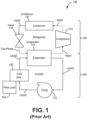
- FIG. 1 shows two-fluid cooling cycle 100, which is configured to provide cooling to cold sink 102, which is thermally coupled to one or more components and/or fluids associated with the one or more components (illustrated as heat load 104) to provide cooling thereto.
- Cold sink 102 can be, for example, a cold plate having internal fluid passages for receiving a fluid of two-fluid cooling cycle 100, which absorbs heat from heat load 104.
- Two-fluid cooling cycle 100 includes coolant loop 106 and refrigerant loop 108.
- two-fluid cooling cycle 100 may be described as a vapor cycle loop that is thermally connected to a liquid loop.
- Coolant loop 106 is a closed-loop system that includes cold sink 102, evaporator 110, and pump 112.
- Coolant loop 106 includes a coolant fluid, which can be continuously cycled through a closed-loop flow path through cold sink 102, evaporator 110, and pump 112.
- Coolant liquid passes through cold sink 102 where it picks up heat from heat load 104 and increases in temperature. The heated coolant enters evaporator 110 where excess heat is extracted and the coolant is cooled.
- Refrigerant loop 108 includes evaporator 110, compressor 114, condenser 116, and expansion valve 118.
- Refrigerant loop 108 is a closed-loop system through which a refrigerant can be continuously cycled.
- Evaporator 110 is part of both coolant loop 106 and refrigerant loop 108.
- Evaporator 110 receives, as a first working fluid, the coolant of coolant loop 106 and, as a second working fluid, a refrigerant of refrigerant loop 108. The refrigerant picks up heat from the coolant of coolant loop 106 within evaporator 110 and enters a vapor phase.
- the refrigerant is supplied to compressor 114 as a saturated or superheated vapor, is cooled to a liquid state by condenser 116, is expanded to an evaporator pressure through expansion valve 118 and returned to evaporator 110 as a two-phase fluid where it will pick up heat and vaporize as it absorbs heat from the coolant of coolant loop 106.
- the closed-loop system of two-fluid cooling cycle 100 allows for the use of compressors (e.g., scroll compressors) that require lubrication for operation.
- a lubricant is mixed with the refrigerant in refrigerant loop 108 which continuously cycles through compressor 114. While two-fluid cooling cycle 100 is capable of providing thermal management of temperature sensitive components, it does so at the expense of system efficiency, size, and weight due to the required components and inefficiencies thereof.
- a cooling system includes a liquid loop, a vapor compression loop, and a heat exchanger in fluid communication with each of the liquid loop and the vapor compression cycle loop.
- the liquid loop includes a cold sink for cooling a heat load.
- the vapor compression cycle loop is fluidly coupled to the liquid loop by a separator, which is configured to separate a two-phase form of a working fluid received from the cold sink into a vapor form of the working fluid and a liquid form of the working fluid.
- a method of recovering a lubricant in a hybrid vapor compression cooling system includes separating, by a separator, a vapor form of a working fluid from a liquid form of a working fluid, wherein the working fluid comprises the lubricant and wherein the lubricant is preferentially separated with the liquid form of the working fluid; delivering the liquid form of the working fluid from the separator to a liquid loop, the liquid loop comprising a pump and a cold sink fluidly coupled in flow series, the cold sink in fluid communication with a separator inlet; delivering the vapor form of the working fluid from the separator to a vapor compression cycle loop, the vapor compression cycle loop comprising a compressor, a condenser, and an expansion valve fluidly coupled in flow series, the expansion valve fluidly coupled to a separator inlet; delivering a first portion of the working fluid in the liquid loop to the cold sink; and delivering a second portion of the working fluid in the liquid loop to the vapor compression cycle loop.
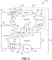
- FIG. 2 is a schematic illustration of single-fluid, two-phase cooling system 200.
- FIG. 3 is a schematic illustration of single-fluid, two-phase cooling system 300.
- Systems 200 and 300 are hybrid vapor compression cycle (VCC) with direct pumped two-phase refrigerant loops that are lighter weight and more efficient than the indirect cooling provided by two-fluid cooling cycle 100 shown in FIG. 1 .
- VCC hybrid vapor compression cycle
- systems 200 and 300 obtain these advantages by replacing evaporator 110 of two-fluid cooling cycle 100 with a separator, which requires no temperature difference to drive heat transfer or surface area for heat transfer.
- systems 200 and 300 are configured to allow a lubricant to be continuously cycled with a working fluid through the VCC loop enabling the use of compressors (e.g., scroll compressors) that require lubrication for operation.
- compressors e.g., scroll compressors
- Systems 200 and 300 are configured to operate with a single working fluid (refrigerant), which is supplied to a cold sink 202, 302 (e.g., cold plates) that can be thermally coupled to one or more heat loads (not shown) to provide cooling thereto.
- Heat loads can be, for example and without limitations, power electronics, electronic devices, a working fluid line of a cooling loop/cycle, or the like, and/or portions thereof as will be appreciated by those of skill in the art.
- the working fluid used in systems 200 and 300 can be a refrigerant, for example and without limitation, 1,1,1,2-Tetrafluoroethane (R-134a) or 2,3,3,3-Tetrafluoropropene (R-123yf). Other refrigerants may be used without departing from the scope of the present disclosure.
- the working fluid is cycled through systems 200 and 300 as a liquid, two-phase fluid, and saturated vapor as shown in FIGS. 2 and 3 .
- FIG. 2 shows system 200, cold sink 202, pumped two-phase loop (referred to hereinafter as “liquid loop”) 204, VCC loop (referred to herein after as “vapor loop”) 206, pump 208, separator 210, compressor 212, condenser 214, expansion valve 216, heat exchangers 218, 219, metering elements 220 and 222, fluid lines 224-233, separator inlets 236, 237 and outlets 238, 239, pump inlet 240 and outlet 242, cold sink inlet 244 and outlet 246, heat exchanger inlets 248, 250 and outlets 252 and 254, compressor inlet 256 and outlet 258, condenser inlet 260 and outlet 262, and expansion valve inlet 264 and outlet 266.
- liquid loop pumped two-phase loop
- VCC loop referred to herein after as “vapor loop”
- Fluid lines 224-233 schematically illustrate the flow of fluid between components of system 200 and do not necessarily represent the arrangement of fluid conduits. For example, some of fluid lines 224-233 may be combined in a single conduit upstream or downstream of a component. Likewise, labelling of inlets and outlets of components of system 200 is provided merely to illustrate a direction of fluid flow and is not intended to limit the invention.
- Liquid loop 204 includes pump 208, cold sink 202, and separator 210. In some embodiments, liquid loop 204 can include heat exchanger 219.
- Vapor loop 206 includes separator 210, compressor 212, condenser 214, and expansion valve 216.
- Liquid loop 204 is fluidly coupled to vapor loop 206 via separator 210 and via compressor 212 through heat exchanger 218.
- System 200 can include additional components not shown as may be required for thermal management and/or fluid control.
- the terms "fluidly coupled” and “in fluid communication” are used interchangeably herein and denote an ability to transfer fluid therebetween.
- separator 210 is arranged downstream of expansion valve 216 and cold sink 202.
- Separator 210 is arranged upstream of compressor 212 and pump 208.
- Pump 208 and a cold sink 202 are fluidly coupled in flow series.
- Cold sink 202 is arranged downstream of pump 208.
- Compressor 212, condenser 214, and expansion valve 216 are fluidly coupled in flow series.
- Compressor 212 is arranged downstream of each of separator 210 and heat exchanger 218 and is arranged upstream of condenser 214.
- Condenser 214 is arranged downstream of compressor 212 and upstream of heat exchanger 218.
- Heat exchanger 218 is arranged upstream of each of compressor 212 and expansion valve 216.
- Heat exchanger 218 is arranged downstream of each of condenser 214 and pump 208. Pump 208 is arranged downstream of separator 210 and upstream of each of cold sink 202 and heat exchanger 218.
- Cold sink 202 is arranged upstream of separator 210.
- Heat exchanger 219 can be arranged along liquid loop 206 between cold sink 202 and separator 210.
- outlet 238 of separator 210 is fluidly coupled to inlet 240 of pump 208, as shown by fluid line 224.
- Outlet 242 of pump 208 is fluidly coupled to one or more inlets 244 of cold sink 202 via one or more metering elements 220, as illustrated by fluid line 225.
- One or more outlets 246 of cold sink 202 are fluidly coupled to inlet 236 of separator 210, as illustrated by fluid line 226.
- Outlet 242 of pump 208 is additionally fluidly coupled to vapor loop 206 via heat exchanger 218.
- Outlet 242 of pump 208 is fluidly coupled to inlet 248 of heat exchanger 218, as illustrated by fluid line 227.
- Outlet 252 of heat exchanger 218 is fluidly coupled to inlet 256 of compressor 212 of vapor loop 206, as illustrated by fluid line 228.
- outlet 239 of separator 210 is fluidly coupled to inlet 256 of compressor 212, as illustrated by fluid line 229.
- Outlet 258 of compressor 212 is fluidly coupled to inlet 260 of condenser 214, as illustrated by fluid line 230.
- Outlet 262 of condenser 214 is fluidly coupled to inlet 250 of heat exchanger 218, as illustrated by fluid line 231.
- Outlet 254 of heat exchanger 218 is fluidly coupled to inlet 264 of expansion valve 216, as illustrated by fluid line 232.
- Inlet 250 of heat exchanger 218 is fluidly coupled to outlet 254 of heat exchanger.
- Inlet 250 and outlet 254 of heat exchanger 218 are fluidly separated from inlet 248 and outlet 252 of heat exchanger 218.
- Outlet 266 of expansion valve 216 is fluidly coupled to inlet 237 of separator 210, as illustrated by fluid line 233.
- inlets 236 and 237 of separator can be a single inlet fed by fluid lines 226 and 233, which can be combined upstream of separator 210.
- system 200 utilizes a single working fluid (e.g., refrigerant) and separator 210, which divides the flows of working fluids (vapor and liquid) between liquid loop 204 and vapor loop 206.
- working fluid e.g., refrigerant
- separator 210 which divides the flows of working fluids (vapor and liquid) between liquid loop 204 and vapor loop 206.
- Separator 210 receives the working fluid in the two-phase state from cold sink 202 of liquid loop 204 and expansion valve 216 of vapor loop 206.
- the two-phase working fluid is separated into liquid and vapor components within separator 210.
- the liquid portion of the working fluid is delivered to liquid loop 206 for cooling a thermal load in thermal communication with cold sink 202.
- the vapor portion of the working fluid is directed to vapor loop 206 wherein it is returned to a two-phase state via compressor 212, condenser 214, and expansion valve 216.
- Separator 210 may be a gravity driven component configured to separate the denser liquid phase from the less dense gaseous vapor phase.
- Compressor 212 arranged downstream of separator 210 can pull the vapor phase of the working fluid out of separator 210 while gravity acts to pull the liquid portion of the working fluid away from the vapor portion of the working fluid.
- Pump 208, arranged downstream of separator 210 may be used to aid in pulling the liquid working fluid from separator 210 through liquid loop 204. It will be appreciated that separator 210 is not limited to a gravity-type separator. For example, centrifugal gas-liquid separators may be used without departing from the scope of the present disclosure.
- the liquid portion of the working fluid received in liquid loop 204 from separator 210 is increased in pressure through pump 208 and provided to cold sink 202 for cooling purposes.
- the working fluid within liquid loop 406 is maintained in liquid form as it enters cold sink 202, which may include pressure regulating elements associated with each heat load that is thermally coupled to cold sink 202.
- an inlet manifold associated with the cold sink 202 may be arranged between the pump 208 and cold sink 202 to receive the liquid working fluid.
- a downstream outlet manifold may be arranged at the downstream end of cold sink 202 to receive and combine the working fluid as it exits cold sink 202.
- the working fluid may be in liquid form, two-phase form, or vapor form as it exits the cooling sink 202.
- the working fluid can be joined with the fluid from vapor loop 206 before, at, or in separator 210.
- Heat exchanger 219 can be a thermal energy storage device arranged in liquid loop 204 between cold sink 202 and separator 210.
- Heat exchanger 219 can be, for example and without limitation, a phase change heat exchanger (PCMHX).
- PCMHX phase change heat exchanger
- a vapor portion of the working fluid within separator 210 is directed into vapor loop 206.
- the vapor portion of the working fluid is compressed by compressor 212 and then condensed to a liquid state within condenser 214.
- Condenser 214 can be fluidly coupled to a ram air duct of an aircraft.
- the liquid working fluid is directed through a first flow path of heat exchanger 218 where it can heat liquid working fluid received from pump 208 in a separate flow path.
- the resulting cooled liquid working fluid is then expanded into a two-phase state by expansion valve 216.
- the two-phase fluid from each of liquid loop 204 and the vapor loop 206 are received by separator 210.
- Compressor 212 is lubricated using a lubricant (e.g., oil) suspended in the working fluid of system 200.
- a lubricant e.g., oil
- Lubricant entrained in the two-phase fluid entering separator 210 from expansion valve 216 and cold sink 202 is preferentially separated with the liquid portion of the working fluid separated in separator 210 and delivered to liquid loop 204.
- compressor 212 may receive insufficient amounts of lubricant from separator 210 to maintain operation. Over time, compressor 212 loses lubrication due to accumulation of lubricant in liquid loop 204 without replacement.
- a portion of lubricant laden liquid working fluid exiting pump 208 in liquid loop 204 is pumped through heat exchanger 218 where it is vaporized and fed directly into compressor 212 downstream of separator 210.
- the lubricant is entrained in the vaporized fluid and can lubricate compressor 212 during operation.
- Heat exchanger 218 places the liquid working fluid with lubricant received from pump 208 in liquid loop 204 in thermal communication with the liquid working fluid received from condenser 214 in vapor loop 206.
- Heat exchanger 218 can be for example and without limitation, a shell and tube heat exchanger or other liquid-to-liquid heat exchanger known in the art.
- the liquid working fluid received in heat exchanger 218 from condenser 214 heats the liquid working fluid received in heat exchanger 218 from pump 208 to convert the liquid working fluid received from pump 208 to a vapor phase suitable for delivery to and operation of compressor 212.
- the vaporized working fluid exiting heat exchanger 218 (via outlet 252) can be combined with the vaporized working fluid exiting separator (via outlet 239) upstream of or at an inlet of compressor 212. Since cooling is applied to the liquid working fluid received from condenser 214 in vapor loop 206, the efficiency of the cycle is not significantly reduced. Heat exchanger 218 is arranged between condenser 214 and expansion valve 216 such that the cooled liquid working fluid is received by expansion valve 216. Lubricant entrained in the vaporized working fluid delivered to compressor 212 cycles through vapor loop 206 and is returned to liquid loop 204 via separator 210.
- the amount of lubricant delivered to compressor 212 can be determined by the amount of liquid working fluid directed from pump 208 to heat exchanger 218. Flow of liquid working fluid from pump 208 is split between cold sink 202 and heat exchanger 218.
- One or more metering elements 220 disposed in fluid line 225 and in fluid communication with fluid line 227 can meter fluid flow of working fluid delivered to cold sink 202.
- Metering element 222 disposed in fluid line 227 can modulate fluid flow or change a volume of working fluid delivered to heat exchanger 218.
- the volume of working fluid delivered to heat exchanger 218 can be set based on a lubricant load (amount of lubricant in the working fluid) and a predetermined lubricant demand for operation of compressor 212.
- the lubricant load can be increased over lubricant loads of a conventional refrigerant system to reduce the amount of liquid working fluid delivered to heat exchanger 218 and thereby increase the amount of working fluid available for cooling via cold sink 202.
- One or both metering elements 220 and 222 can be a valve electronically controlled by a controller (not shown). One or both metering elements 220 and 222 can be controlled to modulate fluid flow to heat exchanger 218 and cold sink 202 based on lubricant load and the predetermined lubricant demand for operation of compressor 212.
- System 300 shown in FIG. 3 is substantially similar to system 200 but replaces heat exchanger 218 with evaporator 318 to vaporize a portion of lubricant laden liquid working fluid received from liquid loop 304 for delivery to vapor loop 304.
- FIG. 3 shows system 300, cold sink 302, liquid loop 304, vapor loop 306, pump 308, separator 310, compressor 312, condenser 314, expansion valve 316, evaporator 318, heat exchanger 319, metering elements 320 and 322, fluid lines 324-332, separator inlets 336, 337 and outlets 338, 339, pump inlet 340 and outlet 342, cold sink inlet 344 and outlet 346, evaporator inlet 348 and outlet 350, compressor inlet 356 and outlet 358, condenser inlet 360 and outlet 362, and expansion valve inlet 364 and outlet 366.
- Fluid lines 324-332 schematically illustrate the flow of fluid between components of system 300 and do not necessarily represent the arrangement of fluid conduits. For example, some of fluid lines 324-332 may be combined in a single conduit upstream or downstream of a component. Likewise, labelling of inlets and outlets of components of system 300 is provided merely to illustrate a direction of fluid flow and is not intended to limit the invention.
- Liquid loop 304 includes pump 308, cold sink 302, and separator 310. In some embodiments, liquid loop 304 can include heat exchanger 319.
- Vapor loop 306 includes separator 310, compressor 312, condenser 314, and expansion valve 316. Liquid loop 304 is fluidly coupled to vapor loop 306 via separator 310 and via compressor 312 through evaporator 318.
- System 300 can include components not shown as may be required for thermal management and/or fluid control.
- separator 310 is arranged downstream of expansion valve 316 and cold sink 302. Separator 310 is arranged upstream of compressor 312 and pump 308. Compressor 312 is arranged downstream of separator 310 and heat exchanger 318 and arranged upstream of condenser 314. Condenser 314 is arranged downstream of compressor 312 and upstream of expansion valve 316. Evaporator 318 is arranged upstream of compressor 312. Evaporator 318 is arranged downstream of pump 308. Pump 308 is arranged downstream of separator 310 and upstream of cold sink 302 and evaporator 318. Cold sink 302 is arranged upstream of separator 310. Heat exchanger 319 can be arranged along liquid loop 306 between cold sink 302 and separator 310.
- outlet 338 of separator 310 is fluidly coupled to inlet 340 of pump 308 as shown by fluid line 324.
- Outlet 342 of pump 308 is fluidly coupled to one or more inlets 344 of cold sink 302 via one or more metering elements 320 as illustrated by fluid line 325.
- One or more outlets 346 of cold sink 302 are fluidly coupled to inlet 336 of separator 310 as illustrated by fluid line 326.
- Outlet 342 of pump 308 is additionally fluidly coupled to vapor loop 306 via evaporator 318.
- Outlet 342 of pump 308 is fluidly coupled to inlet 348 of evaporator 318 as illustrated by fluid line 327.
- Outlet 350 of evaporator 318 is fluidly coupled to inlet 352 of compressor 312 of vapor loop 306 as illustrated by fluid line 328.
- outlet 339 of separator 310 is fluidly coupled to inlet 356 of compressor 312 as illustrated by fluid line 329.
- Outlet 358 of compressor 312 is fluidly coupled to inlet 360 of condenser 314 as illustrated by fluid line 330.
- Outlet 362 of condenser 314 is fluidly coupled to inlet 364 of expansion valve 316 as illustrated by fluid line 331.
- Outlet 366 of expansion valve 316 is fluidly coupled to inlet 337 of separator 310 as illustrated by fluid line 332.
- inlets 336 and 337 of separator can be a single inlet fed by fluid lines 326 and 332, which can be combined upstream of separator 310.
- system 300 utilizes a single fluid (e.g., refrigerant) and separator 310, which divides the flows of fluids of the refrigerant (vapor and liquid) between liquid loop 304 and vapor loop 306.
- a single fluid e.g., refrigerant
- separator 310 which divides the flows of fluids of the refrigerant (vapor and liquid) between liquid loop 304 and vapor loop 306.
- System 300 does not include heat exchanger 218 of system 200. Heat exchanger 218 is replaced with evaporator 318 in system 300. Evaporator 318 of system 300 is configured to provide the same function as heat exchanger 218 of system 200. Specifically, evaporator 318 is configured to vaporize the lubricant laden working fluid of liquid loop 204 received from pump 308 to produce a vaporized working fluid suitable for delivery to compressor 312 and including entrained lubricant for lubrication of compressor 312 during operation. Whereas system 200 utilizes heat from liquid working fluid exiting condenser 214 of vapor loop 206 for vaporizing lubricant laden liquid working fluid received from liquid loop 204, system 300 is configured for operation with an external heat load (not shown).
- Evaporator 318 is a heat exchanger. Evaporator 318 places the liquid working fluid with lubricant received from pump 308 in liquid loop 304 in thermal communication with a heat load (e.g., electronics) requiring cooling. Thermal energy is transferred from the heat load to the liquid working fluid received in evaporator 318 from pump 308 to convert the liquid working fluid received from pump 308 to a vapor phase suitable for delivery to and operation of compressor 312.
- the vaporized working fluid exiting evaporator 318 (via outlet 350) can be combined with the vaporized working fluid exiting separator (via outlet 339) upstream of or at an inlet of compressor 312. Lubricant entrained in the vaporized working fluid delivered to compressor 312 cycles through vapor loop 306 and is returned to liquid loop 304 via separator 310.
- the amount of lubricant delivered to compressor 312 can be determined by the amount of liquid working fluid directed from pump 308 to evaporator 318. Flow of liquid working fluid from pump 308 is split between cold sink 302 and evaporator 318.
- One or more metering elements 320 disposed in fluid line 325 and in fluid communication with fluid line 327 can meter fluid flow of working fluid delivered to cold sink 302.
- Valve 322 disposed in fluid line 327 can modulate fluid flow or change a volume of working fluid delivered to evaporator 318.
- the volume of working fluid delivered to evaporator 318 can be set based on a lubricant load and a predetermined lubricant demand for operation of compressor 312.
- the lubricant load can be increased over lubricant loads of a conventional refrigerant system to reduce the amount of liquid working fluid delivered to evaporator 318 and thereby increase the amount of working fluid available for cooling via cold sink 302.
- One or both metering elements 320 and 322 can be a valve electronically controlled by a controller (not shown). and one or both metering elements 320 and 322 can be controlled to modulate fluid flow to heat exchanger 318 and cold sink 302 based on a lubricant load of the refrigerant and the predetermined lubricant demand for operation of compressor 312.
- Embodiments disclosed herein provide for improved efficiency cooling systems and cycles.
- Embodiments of the present disclosure provide for single-fluid, multi-phase cooling systems that efficiently separate liquid and vapor loops to reduce inefficiencies introduced by having a multi-phase fluid in such cooling cycles.
- the addition of the disclosed heat exchanger or evaporator to deliver vaporized working fluid with entrained lubricant to the compressor of the vapor loop enables the single-fluid, two-phase cooling cycle to operate with compressors, such as scroll compressors, that require lubrication to function.
- a cooling system includes a liquid loop, a vapor compression loop, and a heat exchanger in fluid communication with each of the liquid loop and the vapor compression cycle loop.
- the liquid loop includes a cold sink for cooling a heat load.
- the vapor compression cycle loop is fluidly coupled to the liquid loop by a separator, which is configured to separate a two-phase form of a working fluid received from the cold sink into a vapor form of the working fluid and a liquid form of the working fluid.
- the cooling system of the preceding paragraph can optionally include, additionally and/or alternatively, any one or more of the following features, configurations and/or additional components:
- each of the cold sink and the heat exchanger can be disposed to receive a liquid form of the working fluid from the separator.
- the liquid loop can further include a pump disposed in fluid communication between the separator outlet and each of a cold plate inlet and a heat exchanger inlet.
- the liquid loop can further include a first fluid metering element disposed in a fluid line fluidly coupling the cold sink inlet and a pump outlet, the first fluid metering element configured to meter a flow of the working fluid delivered to the cold sink.
- the liquid loop can further include a second fluid metering element disposed in a fluid line fluidly coupling the heat exchanger inlet and the pump outlet, the second fluid metering element configured to meter a flow of the working fluid delivered to the heat exchanger.
- At least one of the first and second fluid metering elements can be an electronically controlled valve.
- the vapor compression cycle loop can include a compressor, the compressor fluidly coupled to a heat exchanger outlet and the separator outlet to receive a vapor form of the working fluid from each of the heat exchanger and the separator.
- the heat exchanger can be configured to provide thermal communication between the working fluid in the liquid loop and the working fluid in the vapor compression cycle loop.
- the vapor compression cycle loop can further include a condenser disposed downstream of the compressor and an expansion valve disposed downstream of the condenser and upstream of the separator.
- the heat exchanger is disposed between the condenser and the expansion valve and configured to place the working fluid received from the condenser in thermal communication with the working fluid received from the pump.
- the vapor compression cycle loop can further include a condenser disposed downstream of the compressor and an expansion valve disposed downstream of the condenser and upstream of the separator.
- the heat exchanger is configured to place the working fluid received from the pump in thermal communication with a heat load external to the vapor compression cycle loop.
- the heat exchanger can be an evaporator.
- the working fluid comprises a refrigerant and a lubricant.
- the separator can be configured to preferentially separate the lubricant from the vapor form of the working fluid and deliver the lubricant in the liquid form of the working fluid to the liquid loop.
- each of the heat exchanger and the cold plate can be arranged to receive a portion of the working fluid from the pump.
- the heat exchanger can be configured to place the working fluid received from the pump in thermal communication with a heat sink to vaporize the working fluid received from the pump.
- a method of recovering a lubricant in a hybrid vapor compression cooling system includes separating, by a separator, a vapor form of a working fluid from a liquid form of a working fluid, wherein the working fluid comprises the lubricant and wherein the lubricant is preferentially separated with the liquid form of the working fluid; delivering the liquid form of the working fluid from the separator to a liquid loop, the liquid loop comprising a pump and a cold sink fluidly coupled in flow series, the cold sink in fluid communication with a separator inlet; delivering the vapor form of the working fluid from the separator to a vapor compression cycle loop, the vapor compression cycle loop comprising a compressor, a condenser, and an expansion valve fluidly coupled in flow series, the expansion valve fluidly coupled to a separator inlet; delivering a first portion of the working fluid in the liquid loop to the cold sink; and delivering a second portion of the working fluid in the liquid loop to the vapor compression cycle loop.
- the method of the preceding paragraph can optionally include, additionally and/or alternatively, any one or more of the following features, configurations, additional components, and/or steps:
- delivering the second portion of the working fluid to the vapor compression cycle loop can include delivering the second portion of the working fluid to a heat exchanger upstream of the compressor of the vapor compression cycle loop.
- the heat exchanger places the second portion of the working fluid in thermal communication with a heat load to vaporize the second portion of the working fluid.
- the heat exchanger places the second portion of the working fluid in thermal communication with working fluid received from the condenser of the vapor compression cycle loop to vaporize the second portion of the working fluid.
- controlling a volume of the second portion of the working fluid based on a lubricant load and a predetermined lubricant demand for operation of the compressor.
Landscapes
- Engineering & Computer Science (AREA)
- Physics & Mathematics (AREA)
- Mechanical Engineering (AREA)
- Thermal Sciences (AREA)
- General Engineering & Computer Science (AREA)
- Chemical & Material Sciences (AREA)
- Analytical Chemistry (AREA)
- Power Engineering (AREA)
- Compressor (AREA)
- Separation By Low-Temperature Treatments (AREA)
- Compression-Type Refrigeration Machines With Reversible Cycles (AREA)
Applications Claiming Priority (1)
| Application Number | Priority Date | Filing Date | Title |
|---|---|---|---|
| US18/506,768 US12578131B2 (en) | 2023-11-10 | 2023-11-10 | Compressor oil recovery in hybrid VCC pumped two phase loops |
Publications (2)
| Publication Number | Publication Date |
|---|---|
| EP4556814A2 true EP4556814A2 (fr) | 2025-05-21 |
| EP4556814A3 EP4556814A3 (fr) | 2025-08-13 |
Family
ID=93213778
Family Applications (1)
| Application Number | Title | Priority Date | Filing Date |
|---|---|---|---|
| EP24207841.8A Pending EP4556814A3 (fr) | 2023-11-10 | 2024-10-21 | Récupération d'huile de compresseur dans des boucles hybrides, pompées de refroidissement par compression de vapeur à deux phases |
Country Status (2)
| Country | Link |
|---|---|
| US (1) | US12578131B2 (fr) |
| EP (1) | EP4556814A3 (fr) |
Families Citing this family (2)
| Publication number | Priority date | Publication date | Assignee | Title |
|---|---|---|---|---|
| US12578131B2 (en) | 2023-11-10 | 2026-03-17 | Hamilton Sundstrand Corporation | Compressor oil recovery in hybrid VCC pumped two phase loops |
| US12552541B2 (en) * | 2023-11-10 | 2026-02-17 | Hamilton Sundstrand Corporation | Thermal management system for future vertical lift aircraft |
Family Cites Families (82)
| Publication number | Priority date | Publication date | Assignee | Title |
|---|---|---|---|---|
| US3153331A (en) | 1960-11-26 | 1964-10-20 | Normalair Ltd | Aircraft air conditioning system |
| US3681934A (en) | 1970-09-11 | 1972-08-08 | Bangor Punta Operations Inc | Refrigeration and defrost system |
| US4165037A (en) | 1976-06-21 | 1979-08-21 | Mccarson Donald M | Apparatus and method for combined solar and heat pump heating and cooling system |
| US4136528A (en) | 1977-01-13 | 1979-01-30 | Mcquay-Perfex Inc. | Refrigeration system subcooling control |
| US4259848A (en) | 1979-06-15 | 1981-04-07 | Voigt Carl A | Refrigeration system |
| US6866092B1 (en) | 1981-02-19 | 2005-03-15 | Stephen Molivadas | Two-phase heat-transfer systems |
| US4554799A (en) | 1984-10-29 | 1985-11-26 | Vilter Manufacturing Corporation | Multi-stage gas compressor system and desuperheater means therefor |
| US5186013A (en) | 1989-02-10 | 1993-02-16 | Thomas Durso | Refrigerant power unit and method for refrigeration |
| US5174123A (en) | 1991-08-23 | 1992-12-29 | Thermo King Corporation | Methods and apparatus for operating a refrigeration system |
| US5575833A (en) | 1992-09-25 | 1996-11-19 | Parker-Hannifin Corporation | Refrigerant recycling system and apparatus |
| US6330800B1 (en) | 1999-04-16 | 2001-12-18 | Raytheon Company | Apparatus and method for achieving temperature stability in a two-stage cryocooler |
| US6519955B2 (en) * | 2000-04-04 | 2003-02-18 | Thermal Form & Function | Pumped liquid cooling system using a phase change refrigerant |
| KR101338012B1 (ko) | 2002-12-09 | 2013-12-09 | 허드슨 테크놀로지스, 인코포레이티드 | 냉각 시스템 최적화 방법 및 장치 |
| US6820434B1 (en) | 2003-07-14 | 2004-11-23 | Carrier Corporation | Refrigerant compression system with selective subcooling |
| US6948331B1 (en) | 2003-09-12 | 2005-09-27 | Norhrop Grumman Corporation | Environmental control system for an aircraft |
| US7171819B2 (en) | 2005-01-21 | 2007-02-06 | Honeywell International, Inc. | Indirect regenerative air cycle for integrated power and cooling machines |
| EP1856458B1 (fr) | 2005-02-18 | 2011-06-22 | Carrier Corporation | Commande d'un circuit de refrigeration avec un echangeur thermique interne |
| US8118257B2 (en) | 2006-04-28 | 2012-02-21 | Hamilton Sundstrand Corporation | Thermal management system with staged cooling |
| US7845178B1 (en) | 2006-12-19 | 2010-12-07 | Spx Corporation | A/C maintenance system using heat transfer from the condenser to the oil separator for improved efficiency |
| US8584487B2 (en) | 2007-04-10 | 2013-11-19 | Carrier Corporation | Refrigerant system with expander speed control |
| WO2008140454A1 (fr) | 2007-05-14 | 2008-11-20 | Carrier Corporation | Système à compression à vapeur de réfrigérant ayant un économiseur à ballon de détente |
| WO2009029068A1 (fr) | 2007-08-28 | 2009-03-05 | Carrier Corporation | Pompe à chaleur à haut rendement, activée thermiquement |
| JP2011521195A (ja) | 2008-05-14 | 2011-07-21 | キャリア コーポレイション | 輸送冷凍システムおよび運転方法 |
| EP2417406B1 (fr) | 2009-04-09 | 2019-03-06 | Carrier Corporation | Système de compression de vapeur de frigorigène avec dérivation de gaz chaud |
| EP2425189A2 (fr) | 2009-04-29 | 2012-03-07 | Carrier Corporation | Système de refroidissement, de chauffage et de réfrigération à activation thermique transcritique |
| KR20120036811A (ko) * | 2009-05-29 | 2012-04-18 | 파커-한니핀 코포레이션 | 펌프형 루프 구동식 증기 압축 냉각 시스템 |
| US8327651B2 (en) | 2009-07-07 | 2012-12-11 | Hamilton Sundstrand Corporation | Transcritical fluid cooling for aerospace applications |
| US10088202B2 (en) | 2009-10-23 | 2018-10-02 | Carrier Corporation | Refrigerant vapor compression system operation |
| KR20120012613A (ko) | 2010-08-02 | 2012-02-10 | 삼성전자주식회사 | 냉장고 및 그 제어방법 |
| US9109840B2 (en) | 2011-02-17 | 2015-08-18 | Delphi Technologies, Inc. | Unitary heat pump air conditioner having a heat exchanger with an integral accumulator |
| WO2012147367A1 (fr) | 2011-04-28 | 2012-11-01 | パナソニック株式会社 | Dispositif de refroidissement |
| US20140202178A1 (en) * | 2011-06-30 | 2014-07-24 | Michael W. Trumbower | Multiple circuit cooling system |
| EP2629040B1 (fr) | 2012-02-14 | 2020-07-29 | MAHLE International GmbH | Climatiseur à pompe à chaleur unitaire comportant un échangeur de chaleur avec un récepteur monobloc et refroidisseur secondaire |
| US9032753B2 (en) | 2012-03-22 | 2015-05-19 | Trane International Inc. | Electronics cooling using lubricant return for a shell-and-tube style evaporator |
| US20130255289A1 (en) | 2012-03-30 | 2013-10-03 | Hamilton Sundstrand Corporation | Flash tank eliminator |
| US10288325B2 (en) | 2013-03-14 | 2019-05-14 | Rolls-Royce Corporation | Trans-critical vapor cycle system with improved heat rejection |
| WO2014143194A1 (fr) | 2013-03-14 | 2014-09-18 | Rolls-Royce Corporation | Systèmes de refroidissement à co2 transcritique adaptatifs pour applications aérospatiales |
| US10132529B2 (en) | 2013-03-14 | 2018-11-20 | Rolls-Royce Corporation | Thermal management system controlling dynamic and steady state thermal loads |
| US9676484B2 (en) | 2013-03-14 | 2017-06-13 | Rolls-Royce North American Technologies, Inc. | Adaptive trans-critical carbon dioxide cooling systems |
| JP6064753B2 (ja) | 2013-04-05 | 2017-01-25 | 株式会社デンソー | 車両用熱管理システム |
| US9939185B2 (en) | 2013-05-03 | 2018-04-10 | Parker-Hannifin Corporation | Indoor and outdoor ambient condition driven system |
| CN105324616B (zh) | 2013-06-17 | 2019-05-03 | 开利公司 | 制冷系统的油料回收 |
| JP6314821B2 (ja) | 2014-01-29 | 2018-04-25 | 株式会社デンソー | 車両用空調装置 |
| US9897363B2 (en) | 2014-11-17 | 2018-02-20 | Heatcraft Refrigeration Products Llc | Transcritical carbon dioxide refrigeration system with multiple ejectors |
| US10746177B2 (en) | 2014-12-31 | 2020-08-18 | Ingersoll-Rand Industrial U.S., Inc. | Compressor with a closed loop water cooling system |
| RU2698856C2 (ru) | 2015-07-22 | 2019-08-30 | Кэрриер Корпорейшн | Жидкостная система для комбинированного естественного охлаждения и механического охлаждения |
| JP6555112B2 (ja) | 2015-12-11 | 2019-08-07 | 株式会社デンソー | 冷凍サイクル装置 |
| US20170217592A1 (en) | 2016-02-01 | 2017-08-03 | General Electric Company | Aircraft Thermal Management System |
| US10399683B2 (en) | 2016-02-16 | 2019-09-03 | The Boeing Company | Thermal management systems and methods |
| GB2548123A (en) | 2016-03-09 | 2017-09-13 | Rolls Royce Plc | Aircraft superconducting electrical propulsion system |
| DE102016207517A1 (de) | 2016-05-02 | 2017-11-02 | Siemens Aktiengesellschaft | Antriebssystem für Luftfahrzeug mit elektrischem Generator |
| FR3057271B1 (fr) | 2016-10-10 | 2020-01-17 | Arkema France | Utilisation de compositions a base de tetrafluoropropene |
| WO2018204184A1 (fr) | 2017-05-02 | 2018-11-08 | Rolls-Royce North American Technologies Inc. | Procédé et appareil de refroidissement isotherme |
| US10842044B2 (en) | 2017-07-10 | 2020-11-17 | Rolls-Royce North American Technologies, Inc. | Cooling system in hybrid electric propulsion gas turbine engine |
| EP3553422B1 (fr) | 2018-04-11 | 2023-11-08 | Rolls-Royce North American Technologies, Inc. | Système pompé mécaniquement pour la commande directe d'une évaporation isotherme à deux phases |
| US10746440B2 (en) | 2018-04-12 | 2020-08-18 | Rolls-Royce North American Technologies, Inc. | Thermal management system including two-phased pump loop and thermal energy storage |
| US20190316818A1 (en) * | 2018-04-12 | 2019-10-17 | Rolls-Royce Corporation | Thermal energy storage and heat rejection system |
| US10907869B2 (en) | 2018-05-24 | 2021-02-02 | Honeywell International Inc. | Integrated vapor cycle and pumped two-phase cooling system with latent thermal storage of refrigerants for transient thermal management |
| US20200113085A1 (en) * | 2018-10-05 | 2020-04-09 | Villanova University | System and method for recovering and upgrading waste heat while cooling devices |
| US11230384B2 (en) | 2019-04-23 | 2022-01-25 | Joby Aero, Inc. | Vehicle cabin thermal management system and method |
| CN112013260B (zh) | 2019-05-29 | 2025-07-18 | 开利公司 | 用于换热系统的润滑剂回收系统以及换热系统 |
| US11561033B1 (en) | 2019-06-18 | 2023-01-24 | Booz Allen Hamilton Inc. | Thermal management systems |
| CN112577213B (zh) | 2019-09-30 | 2025-05-30 | 杭州三花研究院有限公司 | 热管理系统 |
| WO2021133508A2 (fr) | 2019-11-27 | 2021-07-01 | Colorado State University Research Foundation | Systèmes de refroidissement de turbo-compression ultra-efficaces |
| US11268746B2 (en) | 2019-12-17 | 2022-03-08 | Heatcraft Refrigeration Products Llc | Cooling system with partly flooded low side heat exchanger |
| US11629890B1 (en) | 2019-12-18 | 2023-04-18 | Booz Allen Hamilton Inc. | Thermal management systems |
| US11692779B2 (en) | 2020-01-23 | 2023-07-04 | Rocky Research | Flexible cooling system with thermal energy storage |
| US11732941B1 (en) | 2020-03-26 | 2023-08-22 | Booz Allen Hamilton Inc. | Thermal management systems |
| US12222143B2 (en) | 2020-04-08 | 2025-02-11 | Carrier Corporation | Vapor compression system and method for vapor oil recovery |
| US11162387B1 (en) | 2020-07-14 | 2021-11-02 | Photon Vault, Llc | Multi-temperature heat pump for thermal energy storage |
| US11162388B1 (en) | 2020-08-12 | 2021-11-02 | Rolls-Royce North American Technologies Inc. | Thermal management system to cool transient heat loads with low power consumption |
| US11530844B2 (en) * | 2020-09-30 | 2022-12-20 | Rolls-Royce North American Technologies Inc. | System for supporting intermittent fast transient heat loads |
| US11744042B2 (en) | 2020-11-06 | 2023-08-29 | Rolls-Royce North American Technologies Inc. | Thermal management system with dual-use serial thermal energy storage for system size reduction |
| US12078397B2 (en) | 2020-12-04 | 2024-09-03 | Honeywell International Inc. | Surge control subcooling circuit |
| US11959669B2 (en) | 2021-05-06 | 2024-04-16 | Rolls-Royce North American Technologies Inc. | Bimodal cooling system |
| US20230247795A1 (en) | 2022-01-28 | 2023-08-03 | The Research Foundation For The State University Of New York | Regenerative preheater for phase change cooling applications |
| US11725858B1 (en) | 2022-03-08 | 2023-08-15 | Bechtel Energy Technologies & Solutions, Inc. | Systems and methods for regenerative ejector-based cooling cycles |
| US11988418B2 (en) | 2022-09-14 | 2024-05-21 | Hamilton Sundstrand Corporation | Vapor compression cycle with direct pumped two-phase cooling |
| US12571564B2 (en) | 2022-09-30 | 2026-03-10 | The Curators Of The University Of Missouri | High-efficient integrated compressor-ejector-OHP heat pump |
| WO2025043235A1 (fr) | 2023-08-24 | 2025-02-27 | Honeywell International Inc. | Fluides frigorigènes non inflammables à faible prg et systèmes de fluide frigorigène secondaires comprenant de tels fluides frigorigènes |
| US12578131B2 (en) | 2023-11-10 | 2026-03-17 | Hamilton Sundstrand Corporation | Compressor oil recovery in hybrid VCC pumped two phase loops |
| US20250189189A1 (en) | 2023-12-07 | 2025-06-12 | Hamilton Sundstrand Corporation | Vapor compression cycle with direct pumped two-phase cooling |
-
2023
- 2023-11-10 US US18/506,768 patent/US12578131B2/en active Active
-
2024
- 2024-10-21 EP EP24207841.8A patent/EP4556814A3/fr active Pending
Also Published As
| Publication number | Publication date |
|---|---|
| US12578131B2 (en) | 2026-03-17 |
| US20250155172A1 (en) | 2025-05-15 |
| EP4556814A3 (fr) | 2025-08-13 |
Similar Documents
| Publication | Publication Date | Title |
|---|---|---|
| EP4556814A2 (fr) | Récupération d'huile de compresseur dans des boucles hybrides, pompées de refroidissement par compression de vapeur à deux phases | |
| EP2828591B1 (fr) | Refroidissement de produit électronique à l'aide d'un retour de lubrifiant pour un évaporateur du type à calandre | |
| EP2828590B1 (fr) | Refroidissement de composants électroniques utilisant un retour de lubrifiant pour un évaporateur de type à coque et à tube | |
| EP3619481B1 (fr) | Procédé et appareil de refroidissement isotherme | |
| US6672102B1 (en) | Oil recovery and lubrication system for screw compressor refrigeration machine | |
| EP3553421B1 (fr) | Système de stockage d'énergie thermique et de rejet de chaleur | |
| EP3011237B1 (fr) | Récupération d'huile pour système de réfrigération | |
| CN101517323A (zh) | 具有隔离的外部融化冷却的热能储存和冷却系统 | |
| EP2754980B1 (fr) | Circuit de réfrigération | |
| CN108474596A (zh) | 利用可变的速度在多压缩机系统中进行油分配 | |
| CN206160579U (zh) | 具有液体分离器应用的热回收系统 | |
| EP4339531A1 (fr) | Systeme de refroidissement et systeme de refroidissement d'avion utilisant ce systeme | |
| US9638445B2 (en) | Oil return management in a HVAC system | |
| CN105074357A (zh) | 用于供热通风和空气调节系统的油管理 | |
| EP1671067B1 (fr) | Unites de condensation reparties | |
| JP5871681B2 (ja) | 冷凍サイクル及び冷凍ショーケース | |
| EP4553409A1 (fr) | Système de gestion thermique pour aéronef à portance verticale future | |
| US10309698B2 (en) | Oil return management in a HVAC system | |
| CN100547323C (zh) | 带有次级制冷剂隔离的热能存储和冷却系统 | |
| KR20190130158A (ko) | 열 펌프 및 열 펌프를 작동시키기 위한 방법 | |
| CN211650799U (zh) | 冷能产生设备及低温系统 | |
| US11959673B2 (en) | Enhanced method of lubrication for refrigeration compressors | |
| CN120593441A (zh) | 制冷设备 |
Legal Events
| Date | Code | Title | Description |
|---|---|---|---|
| PUAI | Public reference made under article 153(3) epc to a published international application that has entered the european phase |
Free format text: ORIGINAL CODE: 0009012 |
|
| STAA | Information on the status of an ep patent application or granted ep patent |
Free format text: STATUS: THE APPLICATION HAS BEEN PUBLISHED |
|
| AK | Designated contracting states |
Kind code of ref document: A2 Designated state(s): AL AT BE BG CH CY CZ DE DK EE ES FI FR GB GR HR HU IE IS IT LI LT LU LV MC ME MK MT NL NO PL PT RO RS SE SI SK SM TR |
|
| PUAL | Search report despatched |
Free format text: ORIGINAL CODE: 0009013 |
|
| AK | Designated contracting states |
Kind code of ref document: A3 Designated state(s): AL AT BE BG CH CY CZ DE DK EE ES FI FR GB GR HR HU IE IS IT LI LT LU LV MC ME MK MT NL NO PL PT RO RS SE SI SK SM TR |
|
| RIC1 | Information provided on ipc code assigned before grant |
Ipc: F25B 5/02 20060101AFI20250710BHEP Ipc: F25B 31/00 20060101ALI20250710BHEP Ipc: F25B 41/42 20210101ALI20250710BHEP Ipc: F25B 41/48 20210101ALI20250710BHEP Ipc: F25B 43/02 20060101ALI20250710BHEP Ipc: F25B 49/02 20060101ALI20250710BHEP |
|
| STAA | Information on the status of an ep patent application or granted ep patent |
Free format text: STATUS: REQUEST FOR EXAMINATION WAS MADE |
|
| 17P | Request for examination filed |
Effective date: 20260210 |