EP4556823A1 - Système de refroidissement hybride réutilisable d'une fente froide et d'un joint - Google Patents
Système de refroidissement hybride réutilisable d'une fente froide et d'un joint Download PDFInfo
- Publication number
- EP4556823A1 EP4556823A1 EP23210784.7A EP23210784A EP4556823A1 EP 4556823 A1 EP4556823 A1 EP 4556823A1 EP 23210784 A EP23210784 A EP 23210784A EP 4556823 A1 EP4556823 A1 EP 4556823A1
- Authority
- EP
- European Patent Office
- Prior art keywords
- cryogen
- cryocooler
- vessel
- cooling
- cold
- Prior art date
- Legal status (The legal status is an assumption and is not a legal conclusion. Google has not performed a legal analysis and makes no representation as to the accuracy of the status listed.)
- Pending
Links
Images










Classifications
-
- F—MECHANICAL ENGINEERING; LIGHTING; HEATING; WEAPONS; BLASTING
- F25—REFRIGERATION OR COOLING; COMBINED HEATING AND REFRIGERATION SYSTEMS; HEAT PUMP SYSTEMS; MANUFACTURE OR STORAGE OF ICE; LIQUEFACTION SOLIDIFICATION OF GASES
- F25D—REFRIGERATORS; COLD ROOMS; ICE-BOXES; COOLING OR FREEZING APPARATUS NOT OTHERWISE PROVIDED FOR
- F25D19/00—Arrangement or mounting of refrigeration units with respect to devices or objects to be refrigerated, e.g. infrared detectors
- F25D19/006—Thermal coupling structure or interface
Definitions
- the invention relates to a cooling system of a semiconductor radiation detector or any other electronic or optical component that needs to be cooled to operate or to achieve optimal signal-to-noise ratio; such components as field-effect transistors, superconducting magnets, optical lenses, or infrared sensors.
- the invention provides a highly portable cryogenic apparatus for the detection of radiation, receipt, processing, or transmission of electrical signals, or generation of electromagnetic fields.
- HPGe detectors Semiconductor radiation detectors such as high-purity germanium (HPGe) detectors are widely used for the measurement of gamma-radiation due to the advantage in the energy resolution they provide compared to the scintillation detectors, however, to operate they need to be cooled to low, cryogenic temperatures.
- semiconductor detectors have been cooled by liquid nitrogen. In this cooling method, the energy barrier (characterized by the enthalpy of vaporization) at the phase transition from liquid to gaseous state is used to keep the detector cold.
- cryoaccumulator Sokolov et al. Autonomous Deep-water Gamma Spectrometer based on HPGe Detector. Article. ESARDA Symposium Proceedings, 1999 ).
- cryostats and portable cryocoolers for semiconductor radiation detectors cooling form the state-of-the-art:
- the present invention represents a hybrid cooling system of a cold split and joint.
- the hybrid cooling system is based on a melting cryogen (the passive object of storage of cooling power) and an electromechanical cryocooler (the active object of cooling power production).
- the cooling system is applied to an object that needs to be cooled, such object as a semiconductor radiation detector.
- the invention provides optimal energy resolution for a semiconductor radiation detector by switching the cryocooler off during spectrometric measurements and goes beyond the state-of-the-art by providing methods and corresponding means for making the hybrid cooling system reusable and of a cold split and joint.
- the invention provides the possibility of a repeatable cryocooler detachment from a cooled to the solid state cryogen, and a repeatable cryocooler attachment to the cryogen after its melting, and without the necessity of waiting for the cryogen warm-up above 0 °C (melting point of ice).
- the hybrid cooling system represents a combination of the following two objects: a cryogen (the passive object of storage of cooling power) and an electromechanical cryocooler (the active object of the cooling power production).
- the hybrid cooling system is applied to an object that needs to be cooled, such object as a semiconductor radiation detector.
- the cryogen is filled into a thermally insulated vessel (such as Dewar), and, represents a chemical compound having melting temperature permitting the operation of an object of cooling.
- the cryogen is cooled to a solid crystalline state using an electromechanical cryocooler.
- the cryocooler cold tip is brought into mechanical contact (direct or through a thermal interface material) with a wall of a vessel filled with the cryogen, or, is brought into direct contact with the cryogen itself.
- the cryocooler When the cryogen is cooled to the melting point, the cryocooler is switched off, and the operating temperature of the object of cooling is maintained solely by the melting cryogen, using accumulated at the phase transition energy barrier characterized by the enthalpy of fusion.
- the hybrid cooling system is more effective when the cryocooler cold tip is detached from the cryogen vessel after the cryogen cooling, and optimal weight and size characteristics of a main operational device containing an object of cooling are provided when the cryocooler itself is removed from the device after the cryogen cooling.
- several variants of a hybrid cooling system are provided. These variants can be classified by a type of a cryogen-cryocooler connection chamber and are described below.
- cryogen-cryocooler connection can be made:
- the hybrid cooling system is free from periodic re-filling of externally supplied refrigerants such as liquid nitrogen.
- refrigerants such as liquid nitrogen.
- the main measuring device with the hybrid cooling system has the weight advantage, as after cryogen cooling to the solid state, the device doesn't require batteries for powering the cryocooler, and when the cryocooler itself is removed the weight of the main measuring device is further decreased.
- the present invention is characterized by the set of the following distinctive features:
- the present invention has the following distinctive features:
- the reusable hybrid cooling system of a cold split and joint which contains a passive cooling element - a melting cryogen and an active cooling element - an electromechanical cryocooler is described.
- the invention provides optimal energy resolution for a semiconductor radiation detector by switching the cryocooler off during measurements and it ensures that multiple cooling cycles with connections and disconnections between the cryocooler cold tip and the cryogen can be made without the necessity of waiting for the cryogen warm-up.
- a cryogen is filled into a thermally (vacuum) insulated vessel 2 , having a closed end to which a cryocooler 4 is attached.
- a cryocooler cold tip is attached (brought into mechanical contact) to a wall of a vessel filled with the cryogen in a vacuum-insulated connection chamber 3.
- the walls of the connection chamber represent metal bellows that can be compressed or expanded.
- the cooling system can be applied to any object of cooling positioned in a thermally (vacuum) insulated cryostat 1.
- the cryocooler cold tip 17 is mechanically attached to the wall 13 of the vessel filled with the cryogen 6 by compressing the bellows ( Figs. 3 and 6 ), and after the cryogen cooling, it is mechanically detached by expanding the bellows ( Figs. 4 and 7 ).
- the cryocooler cold tip can be detached from the wall of the vessel filled with the cryogen while the cryogen is cold, however, the cryocooler itself can't be removed from the main operational device, which contains an object of cooling and the cryogen, without breaking the vacuum-tight connection.
- a cryogen is filled into a thermally (vacuum) insulated vessel 2 having a closed-end, to which, by means of a quick-release clamp 3, a cryocooler 4 is attached.
- the attachment is made in a hermetically sealed air connection chamber.
- the cooling system can be applied to any object of cooling positioned in a thermally (vacuum) insulated cryostat 1.
- the cryocooler 23 is attached to an outer cryogen vessel 13 through compatible flanges 18, 21.
- the cryocooler cold tip 15 is put in direct mechanical contact under pressure with a wall of the inner vessel 11 filled with the cryogen in a hermetically sealed by an elastomer O-ring 19 connection chamber, applying a quick-release clamp 20.
- Space 22 available for ambient air in the sealed connection chamber (and therefore the number of water molecules) is minimized to prevent adhesion of the cryocooler cold tip to the wall of the inner vessel due to the formation of ice during cooling.
- the sealed cryogen-cryocooler connection chamber with a minimized free volume available for ambient air allows detachment of the cryocooler after the cryogen cooling, and, multiple cooling cycles with attachments and detachments between the cold wall (having a temperature below 0 °C) of the vessel filled with the cryogen and the cryocooler cold tip can be made when time duration of each connection is minimized.
- the values of the maximum air volume and the maximum time duration of each connection or disconnection (the connection chamber is unsealed) depend on the relative humidity of the ambient air.
- connection and disconnection between a cryocooler cold tip and a cold wall of the vessel filled with the cryogen can be made when the amount of the air in the connection chamber is reduced to a volume of about 1 cm 3 per 1 cm 2 of a contact area (a cryocooler cold tip area), and each connection or disconnection time (the chamber is unsealed) is limited to a period of about 5 seconds.
- the closed inner vessel filled with the cryogen provides the possibility to use a cryogen which can be in the liquid or gaseous state at normal temperature and pressure, and it allows keeping any spatial orientation of the device (i.e. horizontal, vertical, etc.) during attachment of the cryocooler to the cryogen, the cryogen cooling and detachment of the cryocooler, i.e. during the complete cooling and operating cycle.
- the chamber is closed with a Styrofoam plug 12 and is hermetically sealed using an elastomer O-ring 9, applying a quick-release clamp 7 to quick-release flanges 6, 8 as shown in Fig. 11 .
- the inner vessel filled with the cryogen may contain a heat exchanger in the form of a metal foam 1 brazed to the inner vessel walls 2 ( Fig. 12 ).
- a dual-wall neck of the vacuum insulated vessel representing a part of the cryogen-cryocooler connection chamber.
- the wall 6 facing the vacuum is ultra-thin (thickness of about 0.1 mm) and is made from a metal alloy having low thermal conductivity, such as stainless steel, and the wall 8 facing the air from both sides is rather thick (thickness of about 1 mm) and is made from plastic or fiberglass.
- the plastic/fiberglass neck can be mounted using epoxy 9, 10, preferably after vacuum bake-out of the cryogen-cryostat assembly, allowing heat treatment at higher temperatures.
- the invention provides a removable plastic/fiberglass neck mounted using threads 6, 12, as shown in Fig. 13 ; to facilitate the fiberglass neck removal and, therefore, allow for a vacuum bake-out servicing at higher temperatures.
- a cryogen is filled into a vacuum-insulated vessel 4 having an open end.
- the cryogen is liquid at room temperature and normal pressure and a cryocooler cold finger 15 is immersed into it.
- a cryocooler 16 is attached to an outer cryogen vessel 6 using quick-release flanges 10, 12, and applying a quick-release clamp 11; forming a connection chamber, sealed by an elastomer O-ring 13.
- the cryocooler After the cryogen 1 cooling (transferring from liquid to solid aggregate state), the cryocooler is switched off. At this point instead of providing the cooling power the cryocooler conducts heat with a maximum temperature gradient at its tip 3. The cryogen rapidly melts around the cryocooler cold finger 2. Soon the cryocooler cold finger can be detached from the cryogen and the cryocooler itself can be removed from the device without the necessity of warming the whole cryogen up. Multiple cooling cycles with repetitive solidifications of the cryogen can be performed.
- a functional element representing a dual-wall neck of the vacuum-insulated vessel having an open end ( Figs. 15 and 16 ).
- the wall 8 facing vacuum 5 is ultra-thin (thickness of about 0.1 mm) and is made from a metal alloy such as stainless steel, and the wall 9 facing the air is rather thick (thickness of about 1 mm) and is made from plastic or fiberglass.
- the plastic neck is removable and is mounted using epoxy or for easier removal using threads at both ends 10, 11, preferably after a vacuum bake-out of the cryogen-cryostat assembly.
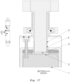
- Another object of the invention is a liquid chemical compound 5 filled into a cryocooler-cryogen connection chamber ( Fig. 17 ) of the second variant of the hybrid cooling system of a cold split and joint.
- the compound having a melting point preferably lower than the melting point of a cryogen, prevents the formation of ice at the cold surfaces and allows immediate detachment of a cryocooler cold tip 3 from a wall 2 of a vessel filled with the cryogen 1 after the cryogen cooling.
- the cryocooler cold tip 3 may not be in direct mechanical contact with the wall of the vessel filled with the cryogen 2, so the liquid compound 5 can serve as a thermal interface material, reducing mechanical load on a cryocooler cold finger 4.
- a standalone cryogen vessel with a neck which accepts either a cryocooler or a cold finger of a standalone cryostat.
- a cryocooler 3 is attached through this neck ( Fig. 19 ) and after a cryogen cooling it is detached and replaced by the cryostat 1, containing an object of cooling ( Fig. 20 ).
- the vessel filled with the cryogen can be either with an open or a closed end.
- the corresponding designs of a closed standalone cryogen vessel and a compatible cryostat are shown in Figs. 21 and 22 .
- the cryostat of Fig. 22 contains an HPGe detector 1 having ion-implanted n+ and p+ electrodes, a cartridge with Zeolite 9, which effectively absorbs water molecules, hydrogen getters 13, and an electrical feedthrough 10 for activation of the getters.
- the cryostat is closed with an endcap 18 made from aluminium, is sealed by a metal, preferably gold-plated O-ring 17, and is evacuated to ultra-high vacuum through a valve 15.
- the cryostat along with the detector is designed so, to be exposed to high-temperature treatment (vacuum bake-out over 350 °C) to achieve low outgassing rates and keep, therefore, ultra-high vacuum insulation for a long time.
- the standalone cryogen vessel can be replaced with an identical one, in which the cryogen is pre-cooled while the previous vessel is in operation.
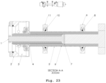
- the detector can be pre-cooled by the cryocooler using a functional element which represents a metal tube with identical flanges at both ends ( Fig. 23 ) .
- the tube is sealed by two elastomer O-rings 8, 10, forming a sealed connection chamber in which a detector cold finger 1 is brought into mechanical contact with a cryocooler cold tip 7.
- a solid tube 6 made from material having low thermal conductivity, such as a PTFE, which fills a space 4 replacing the air.
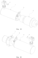
- the reusable hybrid cooling system of a cold split and joint can be used for a variety of applications, as an example, in Figs. 24 and 25 two HPGe spectrometers designed around the concepts of the first and the second variants of the hybrid cooling system are sequentially shown.
- the second spectrometer allows the complete removal of the cryocooler from the cryogen vessel, and therefore, a significant reduction of the weight of a main operational device (the spectrometer) used by an operator for the measurements is provided by the invention.
- Type of the connection chamber Principle of connection
- Contact connection under pressure between a cryocooler cold tip and a wall of a vessel filled with the cryogen. Can be done through a metal thermal interface material such as indium.
- the cryocooler cold tip can be connected to or disconnected from the cold wall (cooled below 0 °C) of the vessel filled with the cryogen.
- the cryocooler itself can't be removed from the main operational device which contains a cryostat and the cryogen. 2.
- a cryocooler (or a detachable cryostat) cold finger is manually plugged into the connection chamber using quick-release flanges, an elastomer O-ring and a a)
- Contact connection under pressure between a cryocooler cold tip and a wall of the vessel filled with the cryogen Can be done through a metal thermal interface material such as indium.
- the cryocooler cold tip can be connected to or disconnected from the cold wall (cooled below 0 °C) of the vessel filled with the cryogen.
- the cryocooler itself can be removed from the main operational device which quick-release clamp.
- Vertical orientation of the cryogen vessel is required during cooling.
- Connection via liquid thermal interface material, preferably having a melting point lower than the melting point of the cryogen. Provides reduced mechanical pressure on a cryocooler cold tip. The vertical orientation of the cryogen vessel is preferable during cooling.
- cryostat contains a cryostat with an object of cooling and the cryogen.
- a hermetically sealed air chamber with an open cryogen vessel and a fixed air volume when sealed.
- a cryocooler or a cryostat cold finger is manually plugged into the connection chamber using quick-release flanges, an elastomer Direct immersion of a cryocooler cold finger in the cryogen.
- the vertical orientation of the cryogen vessel is preferable during cooling and
- the cryocooler cold tip can be connected to the liquid cryogen and disconnected from the cooled cryogen only when some time required for the melting of a part O-ring and a quick-release clamp. sealing.
- the cryogen mustn't be hygroscopic. of the cryogen around the cryocooler coldfinger is passed.
- the cryocooler can be completely removed after that from a main operational device containing an object of cooling and a cryogen.
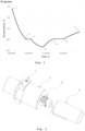
- Fig. 1 a cooling cycle provided by the reusable hybrid cooling system of a cold split and joint is described by the temperature curve.
- a cryocooler is connected to a cryogen vessel; so the cryocooler cold tip is put into mechanical contact (direct or through a thermal interface material) with a wall of the vessel filled with the cryogen, or, with the cryogen itself; and the cryocooler is switched on.
- the cryogen is cooled to its solid state, and the maximum energy barrier at the phase transition characterized by the enthalpy of fusion is accumulated.
- cryocooler is switched off and preferably disconnected.
- the cryogen is melting (molecules of the chemical compound of the cryogen are getting kinetic energy).
- the invention provides the possibility to connect the cryocooler again, for the cryogen cooling, for example at point 7, without the necessity of waiting for the cryogen warm up above 0 °C.
- Fig. 2 the cooling system is applied to an object of cooling which is placed in a cryostat 1.
- the cryostat is integrated with a cryogen vessel 2.
- An inner vessel filled with a cryogen is cooled by a detachable but not removable cryocooler 4.
- a contact connection between a cryocooler cold tip and a wall of the vessel filled with the cryogen is made in a vacuum-insulated connection chamber.
- the walls of the chamber are made compressible/expandable from metal bellows 3, so the length of the chamber can be decreased or increased, and the cryocooler cold tip can be attached to or detached from the wall of the vessel filled with the cryogen without breaking the vacuum.
- an object of cooling such as an HPGe detector 1
- an electrical insulator 2 is placed in a holder 3, and is collimated 4 by a vacuum-compatible material, having high density and a high atomic number, such as tungsten.
- the whole assembly is coupled through a copper adapter 6 with a copper cold finger 7.
- the cold finger is attached to an inner vessel 13 filled with a cryogen 16 by means of vented screws 12.
- the inner vessel is made from aluminium, copper or stainless steel alloy and is wrapped with multilayer insulation 14.
- a cryostat-cryogen assembly is evacuated through a seal-off valve 24 to the pressure of about 10 -6 Torr.
- An outer vessel 15 is made from stainless steel and is integrated with (welded to) the detector cryostat 25.
- the inner vessel is supported by a holder 8.
- the holder prevents movement of the inner vessel with reference to the outer vessel along an X-axis 28.
- the holder is also strong enough to prevent movement of the inner vessel (which is relatively short) across the X-axis.
- the holder allows a cryocooler cold tip 17 to be put into mechanical contact under pressure with the wall of the inner vessel.
- a cryocooler cold head 19 is integrated with (welded to) the outer cryogen vessel using stainless steel bellows 18.
- a liquid/gas feedthrough 22 is foreseen.
- the feedthrough is sealed by a gasket 21 and is closed by PTFE 23 and pressure 20 plugs.
- a molecular sieve 11 is placed between the wall of the inner vessel and the multilayer insulation.
- the cryocooler cold tip is attached to the inner vessel in a vacuum-insulated environment 5, which is shared between the cryostat, the cryogen vessel and a cryogen-cryocooler connection chamber.
- the attachment is made by compressing the bellows and applying contact pressure between the cryocooler cold tip and the wall of the vessel filled with the cryogen.
- Fig. 4 shows the connection chamber shown in Fig. 3 , but the cryogen 1 is cooled to the solid state, the cryocooler is switched off, and the cryocooler cold tip 6 is mechanically detached from the wall of the inner vessel filled with the cryogen 2.
- the vessel is wrapped with the multilayer insulation 3.
- Stainless steel bellows 7 are welded to the outer vessel 4.
- Space 5 is evacuated to the pressure of about 10 -6 Torr.
- a feedthrough 10 made from a stainless steel tube with bellows is foreseen.
- the feedthrough is sealed by a gasket 9 and is closed with PTFE 11 and pressure 8 plugs.
- Fig. 5 the cooling system is applied to an object of cooling, such as an HPGe detector, which is placed in a cryostat 1.
- the cryostat is integrated with a cryogen vessel 2.
- An inner vessel filled with a cryogen is cooled by a detachable but not removable cryocooler 4.
- the contact connection between a cryocooler cold tip and a wall of the vessel filled with the cryogen is made in a vacuum-insulated connection chamber.
- the walls of the chamber are made compressible/expandable from metal bellows 3, so the length of the chamber can be decreased or increased, and the cryocooler cold tip can be attached to or detached from the wall of the vessel filled with the cryogen without breaking the vacuum.
- an object of cooling such as an HPGe detector 1
- an electrical insulator 2 is placed in a holder 3, and is collimated 4 by a vacuum-compatible material, having high density and a high atomic number, such as tungsten.
- the whole assembly is coupled through a copper adapter 6 with a copper cold finger 7.
- the cold finger is attached to an inner vessel 13 filled with a cryogen 16 by means of vented screws 12.
- the inner vessel is made from aluminium, copper or stainless steel alloy and is wrapped with multilayer insulation 14.
- a cryostat-cryogen assembly is evacuated through a seal-off valve 28 to the pressure of 10 -6 Torr.
- An outer vessel 15 is made from stainless steel and is integrated with (welded to) the detector cryostat 30.
- the inner vessel is supported by a coaxial holder 8 attached to the body of the cryostat by means of screws 9.
- the holder is designed to prevent movement of the inner vessel with reference to the outer vessel along an X-axis 32; so a cryocooler cold tip 17 can be put, manually or electromechanically, into mechanical contact under pressure with the wall of the inner vessel.
- a cryocooler 23 is attached to the outer cryogen vessel using stainless steel bellows 20.
- a liquid feedthrough 27 is foreseen.
- the liquid feedthrough is sealed by a gasket 25 and is closed by PTFE 26 and pressure 24 plugs.
- a molecular sieve 11 is placed between the wall of the inner vessel and the multilayer insulation.
- the cryocooler cold tip is attached to the inner vessel in a vacuum-insulated environment 5.
- the attachment is made by compressing the bellows and applying contact pressure between the cryocooler cold tip and the wall of the vessel filled with the cryogen.
- a linear-motion bearing 21 is located (welded to the neck).
- the bearing is coupled with the cryocooler cold finger 18.
- Balls of bearing 22 are made from a material having low thermal conductivity such as Zirconia ceramics.
- Fig. 7 shows the connection chamber shown in Fig. 6 , but the cryogen 1 is cooled to the solid state, the cryocooler 12 is switched off, and the cryocooler cold tip 6 is mechanically detached from the wall of the inner vessel filled with the cryogen 2.
- the outer vessel 4 is integrated with the detector cryostat and with the stainless steel bellows 11, which are decompressed.
- the linear-motion bearing 9 is located at the end of the neck 8 of the vessel filled with the cryogen.
- the bearing is coupled with the cryocooler cold finger 7.
- the balls of bearing 10 are in mechanical contact with the cryocooler cold finger.
- a space 5 between the vessels and the cryocooler cold finger and the inner vessel neck is evacuated to the pressure of about 10 -6 Torr.
- the liquid feedthrough 16 made from stainless steel bellows is foreseen.
- the liquid feedthrough is sealed by the gasket 14 and is closed by the PTFE 15 and pressure 13 plugs.
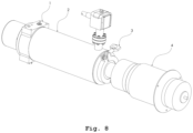
- Fig. 8 the reusable hybrid cooling system of a cold split and joint is shown.
- the system contains a cryostat 1 (with an object of cooling) integrated with (welded to) a cryogen vessel 2.
- the cryogen is cooled by a detachable and removable cryocooler 4.
- a contact connection under pressure between the cryocooler cold tip and a wall of a vessel filled with the cryogen is made in a connection chamber in which the air volume is minimized.
- the chamber is sealed by an elastomer O-ring and the contact connection under pressure is achieved by applying a quick-release clamp 3. Due to the application of a quick-release connection interface (i.e. quick-release flanges and the quick-release clamp), the cryocooler-cryogen split/joint time (the chamber is unsealed) can be short (less than 10 seconds), what makes the cooling system reusable.
- a quick-release connection interface i.e. quick-release flanges and the quick-release clamp
- Fig. 9 an object of cooling, such as a planar HPGe detector 1, is surrounded by an electrical insulator 2, is placed in a detector holder 3 and is collimated 4.
- the whole assembly is coupled through a copper adapter 5 with a copper cold finger 6.
- the cold finger is attached to an inner vessel 11 filled with a cryogen 14 using vented screws.
- the cryogen could be in the liquid or gaseous state at normal temperature and pressure.
- the inner vessel is made from stainless steel, aluminium or oxygen-free copper and is wrapped with a multilayer insulation 12. Space 9 is evacuated through a seal-off valve 29 to the pressure of about 10 -6 Torr.
- An outer vessel 13 is made from stainless steel and is integrated with the detector cryostat.
- the inner vessel is supported coaxially with reference to the outer vessel by a holder 8 via a thermal bridge 7, what prevents the neck 17 from deformation.
- the neck is made from stainless steel or fiberglass.
- the cryostat has electrical feedthroughs 10, is closed by an aluminium endcap 31, and is sealed by an elastomer or metal O-ring 30.
- a liquid feedthrough 28 made from stainless steel is foreseen.
- the feedthrough is sealed by a gasket 26 and is closed with PTFE 27 and pressure 25 plugs.
- a molecular sieve 16 is placed between the wall of the inner vessel and the multilayer insulation.
- a cryocooler cold tip 15 is attached to the wall of inner vessel 11 in a sealed by an elastomer O-ring 19 connection chamber.
- the attachment is made through quick-release flanges 18, 21 using a quick-release clamp 20, applying contact pressure to the cryocooler cold tip (to achieve good thermal transfer), and compressing the O-ring.
- the space 22 between a cryocooler cold finger 24 and the neck, filled with ambient air, is minimized.
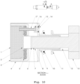
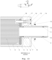
- Fig. 10 shows the connection chamber of the cooling system shown in Fig. 9 , but the cryogen 1 is frozen, and the cryocooler 13 is in the process of splitting from the cryogen vessel 4.
- connection chamber is unsealed by removing the quick-release clamp, liberating the flanges 9, 11, and decompressing the O-ring 10.
- the cryocooler cold tip 6 is detached from the wall of the inner vessel 2.
- Ambient air 12 fills the space between the cryocooler cold finger 7 and the inner vessel neck 8.
- the liquid feedthrough 15 made from stainless steel is foreseen. It is closed by the PTFE plug 16 and is sealed by the gasket 15 using the pressure plug 14. Space between the inner and the outer vessels of the Dewar is evacuated to the pressure of about 10 -6 Torr. To support a high vacuum, the molecular sieve 5 is placed between the wall of the inner vessel and the multilayer insulation 3.
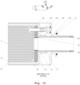
- Fig. 11 shows the connection chamber of the cooling system shown in Fig. 9 , but the cryogen 1 is frozen and the cryocooler is detached.
- the cryogen-cryocooler connection chamber is closed by a PTFE or Styrofoam plug 12, which effectively removes air 11 from the connection chamber.
- the connection chamber is hermetically sealed by an elastomer O-ring 9, using a quick-release clamp 7 and a cork with a flange 8 compatible with the cryogen vessel flange 6. Both measures, along with a prompt cryocooler attachment and detachment, reduce the amount of ice formed at the cold surfaces in the connection chamber and prevent adhesion of the cryocooler cold tip to the wall of the vessel filled with the cryogen; what is essential for a reusable operation of the cooling system.
- the liquid feedthrough 15 made from stainless steel is foreseen. It is closed by the PTFE plug 16 and is sealed with the gasket 14 using the pressure plug 13.
- the space 5 between the inner 2 and the outer 4 vessels of the Dewar is evacuated to the pressure of about 10 -6 Torr.
- the molecular sieve 17 is placed between the wall of the inner vessel and the multilayer insulation 3.
- a cryogen Dewar has a dual neck.
- the wall of a neck 6 facing vacuum 5 is ultrathin (about 0.1 mm) and is made from a metal alloy such as stainless steel, and the wall of a neck 8 facing the air from both sides is relatively thick (about 1 mm), to provide good mechanical strength, and is made from fiberglass (or plastic).
- the dual-neck provides improved vacuum outgassing characteristics compared to a single fiberglass neck, or improved thermal conductivity values compared to a single thicker stainless steel neck.
- the fiberglass neck is mounted using epoxy 9, 10.
- the air 7 between the necks is trapped and doesn't penetrate in a cryocooler-cryogen connection chamber.
- a metal foam 1 is placed inside an inner vessel 2.
- the foam serves for the creation of centers of crystallization, and, distributes thermal gradients more uniformly across the cryogen volume.
- the cryogen is filled in the inner vessel through a feedthrough 15, which is hermetically closed by a pressure plug 13, and is sealed with an elastomer or copper gasket 14.
- a cryogen Dewar has a dual neck.
- the wall of a neck 9 facing vacuum 5 is ultrathin and is made from a metal alloy having low thermal conductivity such as stainless steel, and the wall of a neck 10 facing the air from both sides is relatively thick and is made from fiberglass or plastic.
- the fiberglass neck is mounted using threads 6, 12, preferably after a vacuum bake-out of a cryostat-cryogen vessel assembly.
- Two elastomer O-ring seals 7, 11 are foreseen; the seals block air 8 in between the two necks, so the air can't penetrate to the sealed connection chamber.
- a metal foam 1 is brazed to the walls of an inner vessel 2. After the cryogen filling a liquid/gas feedthrough 17 is hermetically closed by a plug 15 and is sealed with a gasket 16. Such configuration of the feedthrough allows cryogen filling after a vacuum bake-out of the cryostat-cryogen assembly.
- FIG. 14 an inner vessel 4, filled with a cryogen being in a liquid state at room temperature and normal pressure, has an open end; and a cryocooler cold finger 15 is brought in direct contact with the cryogen. Most of the volume of the cryogen is in a solid crystalline state 1, however, a part of the cryogen volume 2 is melted around the cryocooler cold finger and its tip 3.
- the Figure illustrates the last phase of the following cycle:
- a vessel 1 to be filled with a cryogen has an open end, and a cryogen Dewar has a dual neck.
- the wall of a neck 8 facing vacuum 5 is ultrathin and is made from a metal alloy such as stainless steel, and the wall of a neck 9 facing air 4 from both sides is made from fiberglass or plastic and is relatively thick.
- the fiberglass neck can be mounted using epoxy 10, 11 as shown in the Figure, or using threads at both ends as shown in Fig. 16 .
- the dual-neck concept allows mounting of the fiberglass neck after a vacuum bake-out of a cryostat-cryogen vessel assembly, what provides the possibility to increase heat treatment temperature.
- a cryocooler cold tip 3 is brought into mechanical contact with a wall 2 of the vessel filled with a cryogen 1.
- a chemical compound 5 having a melting point preferably lower than the melting point of the cryogen is filled in a cryocooler-cryogen connection chamber, so a cryocooler cold finger 4 and its cold tip are immersed into it.
- the liquid chemical compound removes a part of the air from a cryocooler-cryogen connection chamber and prevents access of water molecules of the remaining air to the place of contact between the wall of the cryogen vessel and the cryocooler cold tip; thus, preventing the formation of ice and adhesion of the cryocooler cold tip to the wall of the vessel containing cooled cryogen.
- the detachment of the cryocooler can be done immediately after the cryogen cooling.
- a cryocooler cold finger 4 and a cold tip 3 are brought into mechanical contact with a liquid chemical compound 5 having a melting point preferably lower than the melting point of a cryogen 1.
- the liquid compound serves as a heat (cold) transfer medium between the cryocooler cold tip and a wall of vessel 2 filled with the cryogen, eliminating the requirement for the cryocooler cold tip and the wall of a vessel filled with the cryogen to be in mechanical contact under pressure.
- the usage of a liquid chemical compound as a thermal interface material decreases axial mechanical load on the cryocooler cold finger.
- the detachment of the cryocooler can be done immediately after the cryogen cooling.
- a standalone cryogen vessel 1 is joint with a detachable cryocooler 3.
- the joint is made in a hermetically sealed connection chamber, applying a quick-release clamp 2.
- An inner vessel filled with a cryogen may have either a closed or an open end.
- the cryogen vessel is equipped with an ion pump 4 to support vacuum thermal insulation.
- the cryocooler can be split from the cryogen vessel and the cryogen vessel can be joined with a compatible cryostat afterwards.
- a standalone cryogen vessel 3 is joined with a detachable cryostat 1.
- the joint is made in a hermetically sealed connection chamber, applying a quick-release clamp 2.
- An inner vessel filled with a cryogen may have either a closed or an open end.
- the cryogen vessel is equipped with an ion pump 4 to support vacuum thermal insulation.
- FIG. 21 a design of a detachable standalone cryogen vessel with a single neck is shown.
- An outer vessel 1 has a flange 10 for the connection to a cryocooler or a cryostat.
- the flange can be hermetically sealed by an elastomer O-ring 11 by applying a quick-release clamp.
- the outer vessel is made from stainless steel or other metal alloy and contains a vacuum valve 8, hermetically sealed by a pair of elastomer O-rings 9.
- An inner vessel 5 is made from stainless steel, aluminium or copper alloy, and is attached to the outer vessel through a thermal bridge 12, representing a stainless steel or a fiberglass neck.
- the inner vessel is filled with a cryogen 6 through a liquid/gas feedthrough 16.
- the feedthrough is closed with PTFE 15 and pressure 13 plugs and is sealed by an elastomer O-ring 14.
- Two cartridges with a molecular sieve 4, 7 are attached to the wall of the inner vessel.
- the space 2 between the inner and the outer vessel is evacuated to a high vacuum.
- the inner vessel is wrapped with a multilayer insulation 3.
- the standalone cryogen vessel may also have two similar necks located at opposite ends, so a cryostat and a cryocooler can be connected to the cryogen vessel simultaneously.
- Fig. 22 a design of a detachable standalone cryostat 16 is shown.
- the cryostat has a similar connection interface to a cryocooler, including an outer diameter of the end of a cold finger housing 8 and dimensions of a flange 14, as to be coupled with a standalone cryogen vessel.
- the cryostat contains an object of cooling, such as a planar HPGe detector 1, placed in an electrical insulator 4, and surrounded by a copper holder 2 and a tungsten collimator 3.
- the detector holder is attached through a copper adapter 6 to a copper cold finger 7.
- the cold finger is attached to the cryostat through a long and thin thermal bridge 8 made from a metal alloy of low thermal conductivity, such as stainless steel.
- a cartridge with a molecular sieve (such as Zeolite, which effectively absorbs water molecules) 9 is attached to the cold finger.
- the cryostat also contains hydrogen getters 13, placed behind an infrared screen 12, and an electrical feedthrough 10 for the activation of the getters.
- the cryostat is closed with an endcap made from aluminium 18, is sealed with a metal O-ring 17, and is evacuated through a valve 15.
- the cryostat is designed to achieve an ultra-high vacuum 5 supported for a long time.
- Fig. 23 the cold finger 1 of the vacuum-insulated cryostat 2 shown in Fig. 22 , is coupled with a cryocooler cold tip 7 by means of a tubular metal adapter 5 and two quick-release clamps 9, 11, forming a sealed by two elastomer O-rings 8, 10 connection chamber. Most of the air 4 from the chamber is removed by the application of a PTFE tube 6.
- a design of a spectrometer having the first variant of the hybrid cooling system of a cold split and joint is shown.
- the spectrometer contains a cryostat 1 with an HPGe detector.
- the cryostat is integrated with a cryogen vessel and with a cryocooler as per Figs. 2 , 3 and 4 .
- a cryocooler cold tip is connected to the cryogen in a vacuum environment using bellows.
- An electronics section of the spectrometer 2 contains a preamplifier, an amplifier, a multichannel analyzer, a high-voltage power supply, a temperature logger, and batteries; along with Ethernet 3 and USB 5 data transfer interfaces to the PC, and a socket for the charging the batteries 4.
- the cryocooler attached to an inner frame 8 of the spectrometer body, can be moved back and forth with reference to an outer frame 7 by means of a screw 6, rotated mechanically or electromechanically.
- an air fan 9 is foreseen.
- the spectrometer has a plastic housing 10 and a metal handle 11 and is equipped with a microprocessor with a display 12.
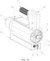
- a design of a spectrometer having the second variant of the hybrid cooling system of a cold split and joint is shown.
- the spectrometer contains a cryostat 1 with an HPGe detector.
- the cryostat is integrated with a cryogen vessel.
- An electronics section of the spectrometer 2 contains a preamplifier, an amplifier, a multichannel analyzer, a high-voltage power supply, a temperature logger, and batteries; along with Ethernet 3 and USB 5 data transfer interfaces to the PC, and a socket for the charging the batteries 4.
- the cryogen vessel has an interface for the connection to a removable cryocooler as shown in Fig. 9 .
- the chamber is closed with a Styrofoam plug and is sealed by an elastomer O-ring using a cork 6 and applying a quick-release clamp 7.
- the spectrometer has a plastic housing 8 and a metal handle 9. The handle is removable; it provides access to a connector for the powering of an ion pump.
- the spectrometer is equipped with a microprocessor with a display 10.
Landscapes
- Engineering & Computer Science (AREA)
- Chemical & Material Sciences (AREA)
- Combustion & Propulsion (AREA)
- Physics & Mathematics (AREA)
- Mechanical Engineering (AREA)
- Thermal Sciences (AREA)
- General Engineering & Computer Science (AREA)
Priority Applications (1)
| Application Number | Priority Date | Filing Date | Title |
|---|---|---|---|
| EP23210784.7A EP4556823A1 (fr) | 2023-11-20 | 2023-11-20 | Système de refroidissement hybride réutilisable d'une fente froide et d'un joint |
Applications Claiming Priority (1)
| Application Number | Priority Date | Filing Date | Title |
|---|---|---|---|
| EP23210784.7A EP4556823A1 (fr) | 2023-11-20 | 2023-11-20 | Système de refroidissement hybride réutilisable d'une fente froide et d'un joint |
Publications (1)
| Publication Number | Publication Date |
|---|---|
| EP4556823A1 true EP4556823A1 (fr) | 2025-05-21 |
Family
ID=88874852
Family Applications (1)
| Application Number | Title | Priority Date | Filing Date |
|---|---|---|---|
| EP23210784.7A Pending EP4556823A1 (fr) | 2023-11-20 | 2023-11-20 | Système de refroidissement hybride réutilisable d'une fente froide et d'un joint |
Country Status (1)
| Country | Link |
|---|---|
| EP (1) | EP4556823A1 (fr) |
Citations (10)
| Publication number | Priority date | Publication date | Assignee | Title |
|---|---|---|---|---|
| US3709932A (en) | 1969-09-22 | 1973-01-09 | Stauffer Chemical Co | Phosphonous dichlorides |
| FR2139624A1 (fr) * | 1971-05-17 | 1973-01-12 | Comp Generale Electricite | |
| GB2139745A (en) * | 1983-04-16 | 1984-11-14 | British Petroleum Co Plc | Cryogenic cell |
| US4510758A (en) | 1983-06-20 | 1985-04-16 | Canberra Industries, Inc. | Convertible cryostat |
| US4658601A (en) | 1983-10-21 | 1987-04-21 | The British Petroleum Company P.L.C. | Cryogenic cell |
| US4851684A (en) | 1986-03-25 | 1989-07-25 | Ortec Incorporated | Modular photon detector cryostat assembly and system |
| US5552609A (en) | 1993-09-09 | 1996-09-03 | Japan Atomic Energy Research Institure | Electric-cooled type semiconductor radioactive ray detector |
| WO2006010772A1 (fr) | 2004-07-28 | 2006-02-02 | Target Systemelectronic Gmbh | Dispositif de refroidissement cryogenique |
| US20100005814A1 (en) * | 2008-07-03 | 2010-01-14 | Bruker Biospin Gmbh | Method for cooling a cryostat configuration during transport and cryostat configuration with transport cooler unit |
| US20170069414A1 (en) * | 2015-09-09 | 2017-03-09 | Samsung Electronics Co., Ltd. | Superconducting magnet apparatus |
-
2023
- 2023-11-20 EP EP23210784.7A patent/EP4556823A1/fr active Pending
Patent Citations (10)
| Publication number | Priority date | Publication date | Assignee | Title |
|---|---|---|---|---|
| US3709932A (en) | 1969-09-22 | 1973-01-09 | Stauffer Chemical Co | Phosphonous dichlorides |
| FR2139624A1 (fr) * | 1971-05-17 | 1973-01-12 | Comp Generale Electricite | |
| GB2139745A (en) * | 1983-04-16 | 1984-11-14 | British Petroleum Co Plc | Cryogenic cell |
| US4510758A (en) | 1983-06-20 | 1985-04-16 | Canberra Industries, Inc. | Convertible cryostat |
| US4658601A (en) | 1983-10-21 | 1987-04-21 | The British Petroleum Company P.L.C. | Cryogenic cell |
| US4851684A (en) | 1986-03-25 | 1989-07-25 | Ortec Incorporated | Modular photon detector cryostat assembly and system |
| US5552609A (en) | 1993-09-09 | 1996-09-03 | Japan Atomic Energy Research Institure | Electric-cooled type semiconductor radioactive ray detector |
| WO2006010772A1 (fr) | 2004-07-28 | 2006-02-02 | Target Systemelectronic Gmbh | Dispositif de refroidissement cryogenique |
| US20100005814A1 (en) * | 2008-07-03 | 2010-01-14 | Bruker Biospin Gmbh | Method for cooling a cryostat configuration during transport and cryostat configuration with transport cooler unit |
| US20170069414A1 (en) * | 2015-09-09 | 2017-03-09 | Samsung Electronics Co., Ltd. | Superconducting magnet apparatus |
Non-Patent Citations (4)
| Title |
|---|
| BONFAIT G ET AL: "20K Energy storage unit", CRYOGENICS, ELSEVIER, KIDLINGTON, GB, vol. 49, no. 7, 1 July 2009 (2009-07-01), pages 326 - 333, XP026156393, ISSN: 0011-2275, [retrieved on 20090320], DOI: 10.1016/J.CRYOGENICS.2009.03.003 * |
| BOYNTON, PROBES, 1975 |
| SOKOLOV ET AL.: "Autonomous Deep-water Gamma Spectrometer based on HPGe Detector", ESARDA SYMPOSIUM PROCEEDINGS,, 1999 |
| TANNER ET AL., A PROBE FOR NEUTRON ACTIVATION ANALYSIS IN A DRILL HOLE USING 252CF, AND A GE(LI) DETECTOR COOLED BY A MELTING CRYOGEN, 1972 |
Similar Documents
| Publication | Publication Date | Title |
|---|---|---|
| US20230042894A1 (en) | Cryogen-free cooling apparatus | |
| JP2961619B2 (ja) | 冷却手段付きクライオスタット | |
| JP7205944B2 (ja) | 極低温超高真空スーツケース | |
| US6332324B1 (en) | Cryostat and magnetism measurement apparatus using the cryostat | |
| JP5713671B2 (ja) | 高度なmr技法向けに材料を過分極化するための方法及び装置 | |
| US5611207A (en) | Cryogenic interface for perpendicular loading of independent measurement inserts | |
| EP1557624A2 (fr) | Systeme cryogenique | |
| Pavese et al. | Routine measurements of specific heat capacity and thermal conductivity of high-T c superconducting materials in the range 4-300 K using modular equipment | |
| US4241592A (en) | Cryostat for borehole sonde employing semiconductor detector | |
| EP4556823A1 (fr) | Système de refroidissement hybride réutilisable d'une fente froide et d'un joint | |
| US20240192099A1 (en) | Cryogenic Analysis Systems and Methods | |
| JP2005172597A (ja) | 核磁気共鳴測定装置 | |
| US11204288B2 (en) | Triple point immersion cell article | |
| EP0265486B1 (fr) | Systeme et ensemble de cryostat modulaire a detecteur de photons | |
| Porter et al. | Detector assembly and the ultralow-temperature refrigerator for XRS | |
| CN121114078B (zh) | 谐振腔低温系统及其测试方法 | |
| JPH05264693A (ja) | 超電導磁気シールド容器 | |
| JP6172979B2 (ja) | 超電導装置 | |
| Hall et al. | Gas contamination effects on pulse tube performance | |
| Giboni et al. | A liquid xenon development and test system | |
| JP3050830B2 (ja) | クライオスタット | |
| JP2001066354A (ja) | 超電導量子干渉デバイス格納用極低温容器 | |
| Winkler et al. | A highly efficient UHV cryo-adapter for a closed cycle refrigerator cold head | |
| Heckman et al. | Qualification and cryogenic performance of cryomodule components at CEBAF | |
| JPH01149406A (ja) | 超電導装置 |
Legal Events
| Date | Code | Title | Description |
|---|---|---|---|
| PUAI | Public reference made under article 153(3) epc to a published international application that has entered the european phase |
Free format text: ORIGINAL CODE: 0009012 |
|
| STAA | Information on the status of an ep patent application or granted ep patent |
Free format text: STATUS: REQUEST FOR EXAMINATION WAS MADE |
|
| 17P | Request for examination filed |
Effective date: 20240919 |
|
| AK | Designated contracting states |
Kind code of ref document: A1 Designated state(s): AL AT BE BG CH CY CZ DE DK EE ES FI FR GB GR HR HU IE IS IT LI LT LU LV MC ME MK MT NL NO PL PT RO RS SE SI SK SM TR |