EP4556836A1 - Wärmetauscher - Google Patents
Wärmetauscher Download PDFInfo
- Publication number
- EP4556836A1 EP4556836A1 EP23210121.2A EP23210121A EP4556836A1 EP 4556836 A1 EP4556836 A1 EP 4556836A1 EP 23210121 A EP23210121 A EP 23210121A EP 4556836 A1 EP4556836 A1 EP 4556836A1
- Authority
- EP
- European Patent Office
- Prior art keywords
- tubes
- manifold
- heat exchanger
- channel
- fluid
- Prior art date
- Legal status (The legal status is an assumption and is not a legal conclusion. Google has not performed a legal analysis and makes no representation as to the accuracy of the status listed.)
- Pending
Links
Images




Classifications
-
- F—MECHANICAL ENGINEERING; LIGHTING; HEATING; WEAPONS; BLASTING
- F28—HEAT EXCHANGE IN GENERAL
- F28D—HEAT-EXCHANGE APPARATUS, NOT PROVIDED FOR IN ANOTHER SUBCLASS, IN WHICH THE HEAT-EXCHANGE MEDIA DO NOT COME INTO DIRECT CONTACT
- F28D1/00—Heat-exchange apparatus having stationary conduit assemblies for one heat-exchange medium only, the media being in contact with different sides of the conduit wall, in which the other heat-exchange medium is a large body of fluid, e.g. domestic or motor car radiators
- F28D1/02—Heat-exchange apparatus having stationary conduit assemblies for one heat-exchange medium only, the media being in contact with different sides of the conduit wall, in which the other heat-exchange medium is a large body of fluid, e.g. domestic or motor car radiators with heat-exchange conduits immersed in the body of fluid
- F28D1/04—Heat-exchange apparatus having stationary conduit assemblies for one heat-exchange medium only, the media being in contact with different sides of the conduit wall, in which the other heat-exchange medium is a large body of fluid, e.g. domestic or motor car radiators with heat-exchange conduits immersed in the body of fluid with tubular conduits
- F28D1/0408—Multi-circuit heat exchangers, e.g. integrating different heat exchange sections in the same unit or heat exchangers for more than two fluids
-
- F—MECHANICAL ENGINEERING; LIGHTING; HEATING; WEAPONS; BLASTING
- F28—HEAT EXCHANGE IN GENERAL
- F28D—HEAT-EXCHANGE APPARATUS, NOT PROVIDED FOR IN ANOTHER SUBCLASS, IN WHICH THE HEAT-EXCHANGE MEDIA DO NOT COME INTO DIRECT CONTACT
- F28D1/00—Heat-exchange apparatus having stationary conduit assemblies for one heat-exchange medium only, the media being in contact with different sides of the conduit wall, in which the other heat-exchange medium is a large body of fluid, e.g. domestic or motor car radiators
- F28D1/02—Heat-exchange apparatus having stationary conduit assemblies for one heat-exchange medium only, the media being in contact with different sides of the conduit wall, in which the other heat-exchange medium is a large body of fluid, e.g. domestic or motor car radiators with heat-exchange conduits immersed in the body of fluid
- F28D1/04—Heat-exchange apparatus having stationary conduit assemblies for one heat-exchange medium only, the media being in contact with different sides of the conduit wall, in which the other heat-exchange medium is a large body of fluid, e.g. domestic or motor car radiators with heat-exchange conduits immersed in the body of fluid with tubular conduits
- F28D1/047—Heat-exchange apparatus having stationary conduit assemblies for one heat-exchange medium only, the media being in contact with different sides of the conduit wall, in which the other heat-exchange medium is a large body of fluid, e.g. domestic or motor car radiators with heat-exchange conduits immersed in the body of fluid with tubular conduits the conduits being bent, e.g. in a serpentine or zig-zag
-
- F—MECHANICAL ENGINEERING; LIGHTING; HEATING; WEAPONS; BLASTING
- F28—HEAT EXCHANGE IN GENERAL
- F28D—HEAT-EXCHANGE APPARATUS, NOT PROVIDED FOR IN ANOTHER SUBCLASS, IN WHICH THE HEAT-EXCHANGE MEDIA DO NOT COME INTO DIRECT CONTACT
- F28D1/00—Heat-exchange apparatus having stationary conduit assemblies for one heat-exchange medium only, the media being in contact with different sides of the conduit wall, in which the other heat-exchange medium is a large body of fluid, e.g. domestic or motor car radiators
- F28D1/02—Heat-exchange apparatus having stationary conduit assemblies for one heat-exchange medium only, the media being in contact with different sides of the conduit wall, in which the other heat-exchange medium is a large body of fluid, e.g. domestic or motor car radiators with heat-exchange conduits immersed in the body of fluid
- F28D1/04—Heat-exchange apparatus having stationary conduit assemblies for one heat-exchange medium only, the media being in contact with different sides of the conduit wall, in which the other heat-exchange medium is a large body of fluid, e.g. domestic or motor car radiators with heat-exchange conduits immersed in the body of fluid with tubular conduits
- F28D1/053—Heat-exchange apparatus having stationary conduit assemblies for one heat-exchange medium only, the media being in contact with different sides of the conduit wall, in which the other heat-exchange medium is a large body of fluid, e.g. domestic or motor car radiators with heat-exchange conduits immersed in the body of fluid with tubular conduits the conduits being straight
- F28D1/0535—Heat-exchange apparatus having stationary conduit assemblies for one heat-exchange medium only, the media being in contact with different sides of the conduit wall, in which the other heat-exchange medium is a large body of fluid, e.g. domestic or motor car radiators with heat-exchange conduits immersed in the body of fluid with tubular conduits the conduits being straight the conduits having a non-circular cross-section
- F28D1/05366—Assemblies of conduits connected to common headers, e.g. core type radiators
- F28D1/05383—Assemblies of conduits connected to common headers, e.g. core type radiators with multiple rows of conduits or with multi-channel conduits
-
- F—MECHANICAL ENGINEERING; LIGHTING; HEATING; WEAPONS; BLASTING
- F28—HEAT EXCHANGE IN GENERAL
- F28F—DETAILS OF HEAT-EXCHANGE AND HEAT-TRANSFER APPARATUS, OF GENERAL APPLICATION
- F28F1/00—Tubular elements; Assemblies of tubular elements
- F28F1/10—Tubular elements and assemblies thereof with means for increasing heat-transfer area, e.g. with fins, with projections, with recesses
- F28F1/12—Tubular elements and assemblies thereof with means for increasing heat-transfer area, e.g. with fins, with projections, with recesses the means being only outside the tubular element
- F28F1/126—Tubular elements and assemblies thereof with means for increasing heat-transfer area, e.g. with fins, with projections, with recesses the means being only outside the tubular element consisting of zig-zag shaped fins
-
- F—MECHANICAL ENGINEERING; LIGHTING; HEATING; WEAPONS; BLASTING
- F28—HEAT EXCHANGE IN GENERAL
- F28F—DETAILS OF HEAT-EXCHANGE AND HEAT-TRANSFER APPARATUS, OF GENERAL APPLICATION
- F28F9/00—Casings; Header boxes; Auxiliary supports for elements; Auxiliary members within casings
- F28F9/02—Header boxes; End plates
- F28F9/0219—Arrangements for sealing end plates into casing or header box; Header box sub-elements
- F28F9/0221—Header boxes or end plates formed by stacked elements
-
- F—MECHANICAL ENGINEERING; LIGHTING; HEATING; WEAPONS; BLASTING
- F28—HEAT EXCHANGE IN GENERAL
- F28F—DETAILS OF HEAT-EXCHANGE AND HEAT-TRANSFER APPARATUS, OF GENERAL APPLICATION
- F28F9/00—Casings; Header boxes; Auxiliary supports for elements; Auxiliary members within casings
- F28F9/02—Header boxes; End plates
- F28F9/0219—Arrangements for sealing end plates into casing or header box; Header box sub-elements
- F28F9/0224—Header boxes formed by sealing end plates into covers
-
- F—MECHANICAL ENGINEERING; LIGHTING; HEATING; WEAPONS; BLASTING
- F28—HEAT EXCHANGE IN GENERAL
- F28F—DETAILS OF HEAT-EXCHANGE AND HEAT-TRANSFER APPARATUS, OF GENERAL APPLICATION
- F28F9/00—Casings; Header boxes; Auxiliary supports for elements; Auxiliary members within casings
- F28F9/02—Header boxes; End plates
- F28F9/0246—Arrangements for connecting header boxes with flow lines
- F28F9/0251—Massive connectors, e.g. blocks; Plate-like connectors
- F28F9/0253—Massive connectors, e.g. blocks; Plate-like connectors with multiple channels, e.g. with combined inflow and outflow channels
Definitions
- the present invention relates to a heat exchanger.
- the present invention relates to an internal heat exchanger for an air conditioning loop for a motor vehicle.
- an air conditioning loop comprises a high pressure fluid circuit and a low pressure fluid circuit.
- An internal heat exchanger is provided in the air conditioning loop to promote heat exchange between a high pressure fluid from the high pressure fluid circuit and a low pressure fluid from the low pressure fluid circuit.
- the internal heat exchanger can be a tube inside tube type heat exchanger, wherein the internal heat exchanger can be integrated inside another part, for example, an accumulator.
- the internal heat exchanger can be a plate type heat exchanger, wherein the internal heat exchanger can have a construction based on a plate type heat exchanger, for example, a plate type chiller.
- An objective of the present invention is to provide a heat exchanger that alleviates the problems in the prior arts. To be more precise, an objective of the present invention is to regulate efficiency of the heat exchanger.
- the heat exchanger for exchanging heat between a first fluid and at least one second fluid comprises: a first manifold; a second manifold spaced apart from the first manifold; a first set of tubes fluidically connected between the first manifold and the second manifold, wherein the first set of tubes is configured to allow a flow of the first fluid from the first manifold to the second manifold; and a second set of tubes fluidically connected between the first manifold and the second manifold, wherein at a first state, a first group of tubes from the second set of tubes is configured to allow a flow of the second fluid from the second manifold to the first manifold; at a second state, a second group of tubes from the second set of tubes is configured to allow the flow of the second fluid from the second manifold to the first manifold; and at a third state, the first group of tubes and the second group of tubes from the second set of tubes are configured to allow the flow of the
- the second set of tubes are stacked one after another with one tube from the first set of tubes in between two tubes from the second set of tubes.
- each tube from the second set of tubes, at both sides, are in contact with one tube from the first set of tubes.
- a first channel is provided in the first manifold and is fluidically connected to the first set of tubes.
- a second channel is provided in the second manifold and is fluidically connected to the first set of tubes.
- first channel and the second channel are configured to allow the flow of the first fluid.
- a fourth channel is provided in the first manifold and is fluidically connected to the first group of tubes from the second set of tubes.
- a fifth channel is provided in the first manifold and is fluidically connected to the second group of tubes from the second set of tubes.
- the third channel and the fourth channel are configured to allow the flow of the second fluid, and the fifth channel is configured not to allow the flow of the second fluid.
- the third channel and the fifth channel are configured to allow the flow of the second fluid, and the fourth channel is configured not to allow the flow of the second fluid.
- the third channel, the fourth channel and the fifth channel are configured to allow the flow of the second fluid.
- the present invention herein provides an air conditioning loop.
- the air conditioning loop comprises: at least one heat exchanger as described in any one of preceding embodiments.
- the first fluid is a low pressure fluid from a low pressure fluid circuit of the air conditioning loop and the second fluid is a high pressure fluid from a high pressure fluid circuit of the air conditioning loop.
- efficiency of the heat exchanger is regulated by switching the heat exchanger to any one of the first state, the second state and the third state.
- the heat exchanger is switched to the third state.
- intermediate efficiency is preferred, the heat exchanger is switched to the first state.
- low efficiency is preferred, the heat exchanger is switched to the second state.
- some elements or parameters may be indexed, such as a first element and a second element.
- this indexation is only meant to differentiate and name elements that are similar but not identical. No idea of priority should be inferred from such indexation, as these may be switched without betraying the invention. Additionally, this indexation does not imply any order in mounting or use of the elements of the invention.
- FIG. 1 illustrates a heat exchanger 100, in accordance with an embodiment of the present invention.
- the heat exchanger 100 comprises a first manifold 200 and a second manifold 300.
- the heat exchanger 100 further comprises a first set of tubes 400 and a second set of tubes 500 that are fluidically connected between the first manifold 200 and the second manifold 300.
- the heat exchanger 100 can comprise the first manifold 200 and the second manifold 300 spaced apart from the first manifold 200.
- the heat exchanger 100 can comprise the first set of tubes 400, at one end, is fluidically connected to first manifold 200 and at another end, is fluidically connected to the second manifold 300. Further, a first fluid can flow from the first manifold 200 to the second manifold 300 through the first set of tubes 400.
- the heat exchanger 100 can comprise the second set of tubes 500, at one end, is fluidically connected to the first manifold 200 and at another end, is fluidically connected to the second manifold 300. Further, a second fluid can flow in different configurations through the second set of tubes 500 at different states of the heat exchanger 100.
- the second fluid can flow from the second manifold 300 to the first manifold 200 through the first group of tubes 500A and the second group of tubes 500B from the second set of tubes 500 at a third state, wherein at the third state, the efficiency of the heat exchanger 100 is high.
- the second set of tubes 500 can be stacked alternatively with the first set of tubes 400.
- the second set of tubes 500 can be stacked one after another with one tube 400 from the first set of tubes 400 in between two tubes 500 from the second set of tubes 500.
- the second set of tubes 500 can be stacked alternatively in a vertical axis with the first set of tubes 400.
- each tube 500 from the second set of tubes 500, at either one side or both sides can be in contact with one tube 400 from the first set of tubes 400.
- each tube 400 from the first set of tubes 400, at either one side or both sides can be in contact with one tube 500 from the second set of tubes 500.
- first set of tubes 400 and the second set of tubes 500 can be any type of tube.
- first set of tubes 400 and the second set of tubes 500 can be a multiport tube.
- first set of tubes 400 and the second set of tubes 500 can be a sandwich tube, wherein each sandwich tube can comprise two tubes with a spacer sandwiched between the two tubes, and respective ends of the two tubes can be fluidically connected to a single orifice.
- the first group of tubes 500A from the second set of tubes 500 can comprise a larger number tubes compared to the second group of tubes 500B from the second set of tubes 500.
- the first group of tubes 500A from the second set of tubes 500 and the second group of tubes 500B from the second set of tubes 500 can comprise at least one tube in common.
- the first group of tubes 500A can comprise all tubes from the second set of tubes 500.
- the second group of tubes 500B can comprise a second subset of tubes from the second set of tubes 500.
- the first group of tubes 500A can comprise a first subset of tubes from the second set of tubes 500.
- the second group of tubes 500B can comprise a second subset of tubes from the second set of tubes 500.
- the first group of tubes 500A from the second set of tubes 500 and the second group of tubes 500B from the second set of tubes 500 does not comprise any tube in common.
- the first group of tubes 500A can comprise tubes numbered 1 to 10 from the second set of tubes 500 numbered 1 to 10.
- the second group of tubes can comprise tubes numbered 1, 3, 5, 7 and 9 from the second set of tubes 500 numbered 1 to 10.
- the first group of tubes 500A can comprise tubes numbered 1 to 7 from the second set of tubes 500 numbered 1 to 10.
- the second group of tubes 500B can comprise tubes numbered 6 to 10 from the second set of tubes 500 numbered 1 to 10.
- the first group of tubes 500A can comprise tubes numbered 1 to 6 from the second set of tubes 500 numbered 1 to 10.
- the second group of tubes 500B can comprise tubes numbered 7 to 10 from the second set of tubes 500 numbered 1 to 10.
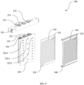
- FIG. 2 and FIG. 3 illustrate two different views of the first manifold 200 of the heat exchanger 100 of FIG. 1 .
- FIG.4 illustrates an exploded view of the first manifold 200 of FIG. 2 .
- the first manifold 200 can comprise a first connection block 210, a first cover 220, at least one first intermediate plate 230 and a first header plater 240 assembled together.
- the first manifold 200 can comprise one first intermediate plate 230.
- the first manifold 200 can comprise two first intermediate plates 230.
- first connection block 210 can be adapted to fluidically connect to the first cover 220.
- the first connection block 210 can comprise a first connection orifice 212 adapted to fluidically connect to a first fluid circuit outside the heat exchanger 100, and a fourth connection orifice 216 and a fifth connection orifice 214 adapted to fluidically connect to a second fluid circuit outside the heat exchanger 100.
- the first cover 220 can comprise a first channel 222, a fourth channel 226 and a fifth channel 224 adapted to fluidically connect to the first connection orifice 212, the fourth connection orifice 216 and the fifth connection orifice 214 respectively.
- the first cover 220 can be adapted to fluidically connect to the at least one first intermediate plate 230.
- the first cover 220 can comprise a first set of channel orifices 222A, a fourth set of channel orifices 226A and a fifth set of channel orifices 224A fluidically connected to the first channel 222, the fourth channel 226 and the fifth channel 224 respectively.
- the at least one first intermediate plate 230 can comprise a first set of intermediate plate orifices 232 adapted to fluidically connect to the first set of channel orifices 222A, and a fourth set of intermediate plate orifices 234 adapted to fluidically connect to the fourth set of channel orifices 226A and the fifth set of channel orifices 224A.
- the at least one first intermediate plate 230 can be adapted to fluidically connect to the first header plate 240.
- the first header plate 240 can comprise a first set of header plate orifices 242 and a fourth set of header plate orifices 244 adapted to fluidically connect to the first set of intermediate plate orifices 232 and the fourth set of intermediate plate orifices 234 respectively.
- first header plate 240 can be adapted to fluidically connect to the first set to tubes 400 and the second set of tubes 500.
- the first set of header plate orifices 242 and the fourth set of header plate orifices 244 of the first header plate 240 can be adapted to fluidically connect to the first set to tubes 400 and the second set of tubes 500 respectively.
- FIG. 5 and FIG. 6 illustrate two different views of the second manifold 300 of the heat exchanger 100 of FIG. 1 .
- FIG. 7 illustrates an exploded view of the second manifold 300 of FIG. 5 .
- the second manifold 300 can comprise a second connection block 310, a second cover 320, at least one second intermediate plate 330 and a second header plater 340 assembled together.
- the second manifold 300 can comprise one second intermediate plate 330.
- the second manifold 300 can comprise two second intermediate plates 330.
- the second connection block 310 can be adapted to fluidically connect to the second cover 320.
- the second connection block 310 can comprise a second connection orifice 312 adapted to fluidically connect to the first fluid circuit outside the heat exchanger 100 and a third connection orifice 314 adapted to fluidically connect to the second fluid circuit outside the heat exchanger 100.
- the second cover 320 can comprise a second channel 322 and a third channel 324 adapted to fluidically connect to the second connection orifice 312 and the third connection orifice 314 respectively.
- the second cover 320 can be adapted to fluidically connect to the at least one second intermediate plate 330.
- the second cover 320 can comprise a second set of channel orifices 322A and a third set of channel orifices 324A fluidically connected to the second channel 322 and the third channel 324 respectively.
- the at least one second intermediate plate 330 can comprise a second set of intermediate plate orifices 332 and a third set of intermediate plate orifices 334 adapted to fluidically connect to the second set of channel orifices 322A and the third set of channel orifices 324A respectively.
- the at least one second intermediate plate 330 can be adapted to fluidically connect to the second header plate 340.
- the second header plate 340 can comprise a second set of header plate orifices 342 and a third set of header plate orifices 344 adapted to fluidically connect to the second set of intermediate plate orifices 332 and the third set of intermediate plate orifices 334 respectively.
- the second header plate 340 can be adapted to fluidically connect to the first set to tubes 400 and the second set of tubes 500.
- the second set of header plate orifices 342 and the third set of header plate orifices 344 of the second header plate 340 can be adapted to fluidically connect to the first set to tubes 400 and the second set of tubes 500 respectively.
- FIG. 8 illustrates the flow of the first fluid in the heat exchanger 100 of FIG. 1 .
- the first fluid can flow through the first channel 222 and the second channel 322.
- the first fluid can flow in a I-flow configuration, wherein the first fluid can flow in through the first connection orifice 212 of the first manifold 200, then flow through the first channel 222, the first set of tubes 400, the second channel 322, and then flow out through the second connection orifice 312 of the second manifold 300.
- FIG. 9 illustrates the flow of the second fluid in the heat exchanger 100 of FIG. 1 , at the first state.
- the second fluid flows through the third channel 324 and the fourth channel 226, and does not flow through the fifth channel 224 at the first state.
- the second fluid can flow in a first I-flow configuration at the first state, wherein the second fluid can flow in through the third connection orifice 314 of the second manifold 300, then flow through the third channel 324, the first group of tubes 500A from the second set of tubes 500, the fourth channel 226, and then flow out through the fourth connection orifice 216 of the first manifold 200.
- FIG. 10 illustrates the flow of the second fluid in the heat exchanger 100 of FIG. 1 , at the second state.
- the second fluid flows through the third channel 324 and the fifth channel 224, and does not flow through the fourth channel 226 at the second state.
- the second fluid can flow in a second I-flow configuration at the second state, wherein the second fluid can flow in through the third connection orifice 314 of the second manifold 300, then flow through the third channel 324, the second group of tubes 500B from the second set of tubes 500, the fifth channel 224, and then flow out through the fifth connection orifice 214 of the first manifold 200.
- FIG. 11 illustrates the flow of the second fluid in the heat exchanger 100 of FIG. 1 , at the third state.
- the second fluid flows through the third channel 324, the fourth channel 226 and the fifth channel 224 at the third state.
- the second fluid can flow in a third I-flow configuration at the third state, wherein the second fluid can flow in through the third connection orifice 314 of the second manifold 300, then flow through the third channel 324, then flow through the first group of tubes 500A and the second group of tubes 500B from the second set of tubes 500 respectively, then flow through the fourth channel 226 and the fifth channel 224 respectively, and then flow out through the fourth connection orifice 216 and the fifth connection orifice 214 of the first manifold 200 respectively.
- the heat exchanger 100 can be switched to any one of the first state, the second state and the third state by controlling the flow of the first fluid and the second fluid in the heat exchanger 100.
- flow control valves can be used to control the flow of the first fluid and the second fluid in the heat exchanger 100.
- the heat exchanger 100 can be an internal heat exchanger of an air conditioning loop that promotes heat exchange between a high pressure fluid from a high pressure fluid circuit of the air conditioning loop and a low pressure fluid from a low pressure fluid circuit of the air conditioning loop.
- the first fluid of the heat exchanger 100 can be a low pressure fluid from the low pressure fluid circuit of the air conditioning loop and the second fluid of the heat exchanger 100 can be a high pressure fluid from the high pressure fluid circuit of the air conditioning loop.
Landscapes
- Engineering & Computer Science (AREA)
- Physics & Mathematics (AREA)
- Thermal Sciences (AREA)
- Mechanical Engineering (AREA)
- General Engineering & Computer Science (AREA)
- Heat-Exchange Devices With Radiators And Conduit Assemblies (AREA)
Priority Applications (2)
| Application Number | Priority Date | Filing Date | Title |
|---|---|---|---|
| EP23210121.2A EP4556836A1 (de) | 2023-11-15 | 2023-11-15 | Wärmetauscher |
| PCT/EP2024/081358 WO2025103844A1 (en) | 2023-11-15 | 2024-11-06 | A heat exchanger |
Applications Claiming Priority (1)
| Application Number | Priority Date | Filing Date | Title |
|---|---|---|---|
| EP23210121.2A EP4556836A1 (de) | 2023-11-15 | 2023-11-15 | Wärmetauscher |
Publications (1)
| Publication Number | Publication Date |
|---|---|
| EP4556836A1 true EP4556836A1 (de) | 2025-05-21 |
Family
ID=88837502
Family Applications (1)
| Application Number | Title | Priority Date | Filing Date |
|---|---|---|---|
| EP23210121.2A Pending EP4556836A1 (de) | 2023-11-15 | 2023-11-15 | Wärmetauscher |
Country Status (2)
| Country | Link |
|---|---|
| EP (1) | EP4556836A1 (de) |
| WO (1) | WO2025103844A1 (de) |
Citations (5)
| Publication number | Priority date | Publication date | Assignee | Title |
|---|---|---|---|---|
| US20090229800A1 (en) * | 2008-03-11 | 2009-09-17 | Mohinder Singh Bhatti | High performance three-fluid vehicle heater |
| KR101580233B1 (ko) * | 2010-07-02 | 2015-12-24 | 한온시스템 주식회사 | 열교환기 |
| US20220080801A1 (en) * | 2018-12-30 | 2022-03-17 | Zhejiang Jizhi New Energy Automobile Technology Co., Ltd | Integrated radiator assembly |
| US20230168048A1 (en) * | 2020-05-04 | 2023-06-01 | Valeo Autosystemy Sp. Z O.O. | Heat exchanger |
| EP4194787A1 (de) * | 2021-12-10 | 2023-06-14 | Valeo Autosystemy SP. Z.O.O. | Wärmetauscher |
-
2023
- 2023-11-15 EP EP23210121.2A patent/EP4556836A1/de active Pending
-
2024
- 2024-11-06 WO PCT/EP2024/081358 patent/WO2025103844A1/en active Pending
Patent Citations (5)
| Publication number | Priority date | Publication date | Assignee | Title |
|---|---|---|---|---|
| US20090229800A1 (en) * | 2008-03-11 | 2009-09-17 | Mohinder Singh Bhatti | High performance three-fluid vehicle heater |
| KR101580233B1 (ko) * | 2010-07-02 | 2015-12-24 | 한온시스템 주식회사 | 열교환기 |
| US20220080801A1 (en) * | 2018-12-30 | 2022-03-17 | Zhejiang Jizhi New Energy Automobile Technology Co., Ltd | Integrated radiator assembly |
| US20230168048A1 (en) * | 2020-05-04 | 2023-06-01 | Valeo Autosystemy Sp. Z O.O. | Heat exchanger |
| EP4194787A1 (de) * | 2021-12-10 | 2023-06-14 | Valeo Autosystemy SP. Z.O.O. | Wärmetauscher |
Also Published As
| Publication number | Publication date |
|---|---|
| WO2025103844A1 (en) | 2025-05-22 |
Similar Documents
| Publication | Publication Date | Title |
|---|---|---|
| US11536496B2 (en) | Heat exchanger and refrigeration cycle apparatus | |
| KR102847642B1 (ko) | 열 관리 부품 | |
| US9797656B2 (en) | Vehicle interior heat exchanger and inter-header connecting member of vehicle interior heat exchanger | |
| US20240003633A1 (en) | Variable flow heat exhanger | |
| US20250158161A1 (en) | Liquid cooling assembly and battery pack | |
| EP4556836A1 (de) | Wärmetauscher | |
| EP4556837A1 (de) | Wärmetauscher | |
| CN218270317U (zh) | 板式换热器及车辆 | |
| US10126065B2 (en) | Heat exchanger assembly having a refrigerant distribution control using selective tube port closures | |
| EP4459747A1 (de) | Wärmeverwaltungsanordnung und batteriewärmeverwaltungssystem | |
| US12460879B2 (en) | Heat exchanger | |
| CN117190758A (zh) | 板式热交换器 | |
| EP3872434B1 (de) | Plattenanordnung | |
| EP4450913A1 (de) | Plattenwärmetauscher | |
| JP3218053B2 (ja) | 凝縮器 | |
| JPH11218396A (ja) | 並設一体型熱交換器及びその製造方法 | |
| EP4464966A1 (de) | Wärmetauscher | |
| CN220083187U (zh) | 微通道换热器、空调 | |
| US12140389B2 (en) | Heat exchanger and heat exchange device | |
| EP4462055B1 (de) | Wärmetauscher | |
| EP0619467B1 (de) | Verdampfer | |
| CN119042842A (zh) | 热管理组件 | |
| EP4624851A1 (de) | Wärmetauscher mit mehreren modi | |
| EP3819578B1 (de) | Wärmetauscher mit steuerungsmitteln | |
| CN119546917A (zh) | 板层叠型热交换器 |
Legal Events
| Date | Code | Title | Description |
|---|---|---|---|
| PUAI | Public reference made under article 153(3) epc to a published international application that has entered the european phase |
Free format text: ORIGINAL CODE: 0009012 |
|
| STAA | Information on the status of an ep patent application or granted ep patent |
Free format text: STATUS: THE APPLICATION HAS BEEN PUBLISHED |
|
| AK | Designated contracting states |
Kind code of ref document: A1 Designated state(s): AL AT BE BG CH CY CZ DE DK EE ES FI FR GB GR HR HU IE IS IT LI LT LU LV MC ME MK MT NL NO PL PT RO RS SE SI SK SM TR |
|
| STAA | Information on the status of an ep patent application or granted ep patent |
Free format text: STATUS: REQUEST FOR EXAMINATION WAS MADE |
|
| 17P | Request for examination filed |
Effective date: 20251121 |
|
| GRAP | Despatch of communication of intention to grant a patent |
Free format text: ORIGINAL CODE: EPIDOSNIGR1 |
|
| STAA | Information on the status of an ep patent application or granted ep patent |
Free format text: STATUS: GRANT OF PATENT IS INTENDED |
|
| RAP1 | Party data changed (applicant data changed or rights of an application transferred) |
Owner name: VALEO ELECTRIFICATION |
|
| RIC1 | Information provided on ipc code assigned before grant |
Ipc: F28D 1/04 20060101AFI20260225BHEP Ipc: F28D 1/047 20060101ALI20260225BHEP Ipc: F28D 1/053 20060101ALI20260225BHEP Ipc: F28F 1/12 20060101ALI20260225BHEP Ipc: F28F 9/02 20060101ALI20260225BHEP |
|
| INTG | Intention to grant announced |
Effective date: 20260305 |