EP4556864A2 - Débitmètre magnéto-inductif - Google Patents
Débitmètre magnéto-inductif Download PDFInfo
- Publication number
- EP4556864A2 EP4556864A2 EP25160691.9A EP25160691A EP4556864A2 EP 4556864 A2 EP4556864 A2 EP 4556864A2 EP 25160691 A EP25160691 A EP 25160691A EP 4556864 A2 EP4556864 A2 EP 4556864A2
- Authority
- EP
- European Patent Office
- Prior art keywords
- voltage
- magnetic
- hold
- sub
- coil current
- Prior art date
- Legal status (The legal status is an assumption and is not a legal conclusion. Google has not performed a legal analysis and makes no representation as to the accuracy of the status listed.)
- Pending
Links
Images

Classifications
-
- G—PHYSICS
- G01—MEASURING; TESTING
- G01F—MEASURING VOLUME, VOLUME FLOW, MASS FLOW OR LIQUID LEVEL; METERING BY VOLUME
- G01F1/00—Measuring the volume flow or mass flow of fluid or fluent solid material wherein the fluid passes through a meter in a continuous flow
- G01F1/56—Measuring the volume flow or mass flow of fluid or fluent solid material wherein the fluid passes through a meter in a continuous flow by using electric or magnetic effects
- G01F1/58—Measuring the volume flow or mass flow of fluid or fluent solid material wherein the fluid passes through a meter in a continuous flow by using electric or magnetic effects by electromagnetic flowmeters
- G01F1/60—Circuits therefor
-
- G—PHYSICS
- G01—MEASURING; TESTING
- G01F—MEASURING VOLUME, VOLUME FLOW, MASS FLOW OR LIQUID LEVEL; METERING BY VOLUME
- G01F1/00—Measuring the volume flow or mass flow of fluid or fluent solid material wherein the fluid passes through a meter in a continuous flow
- G01F1/56—Measuring the volume flow or mass flow of fluid or fluent solid material wherein the fluid passes through a meter in a continuous flow by using electric or magnetic effects
- G01F1/58—Measuring the volume flow or mass flow of fluid or fluent solid material wherein the fluid passes through a meter in a continuous flow by using electric or magnetic effects by electromagnetic flowmeters
- G01F1/586—Measuring the volume flow or mass flow of fluid or fluent solid material wherein the fluid passes through a meter in a continuous flow by using electric or magnetic effects by electromagnetic flowmeters constructions of coils, magnetic circuits, accessories therefor
Definitions
- the invention relates to a magnetic-inductive flow measuring device for determining a flow velocity-dependent measured variable of a flowable medium.
- Magnetic-inductive flow measuring devices are used to determine the flow velocity and volumetric flow of a flowing medium in a pipeline.
- Inline magnetic-inductive flow measuring devices are distinguished from magnetic-inductive flow measuring probes, which are inserted into a lateral opening in a pipeline.
- a magnetic-inductive flow measuring device has a device for generating a magnetic field perpendicular to the flow direction of the flowing medium. Individual coils are usually used for this purpose.
- additional pole pieces are shaped and attached so that the magnetic field lines run across the entire pipe cross-section essentially perpendicular to the transverse axis or parallel to the vertical axis of the measuring tube.
- a magnetic-inductive flow measuring device has a measuring tube on which the device for generating the magnetic field is arranged.
- a pair of measuring electrodes attached to the outer surface of the measuring tube measures an electrical measuring voltage or potential difference perpendicular to the flow direction and the magnetic field. This voltage arises when a conductive medium flows in the direction of flow with a magnetic field applied. Since the measured measuring voltage depends on the velocity of the flowing medium according to Faraday's law of induction, the flow velocity and - with the addition of a known pipe cross-section - the volumetric flow can be determined from the induced measuring voltage.
- magnetic-inductive flow measuring probes In contrast to a magnetic-inductive flowmeter, which comprises a measuring tube for conveying the medium with an attached device for generating a magnetic field penetrating the measuring tube and measuring electrodes, magnetic-inductive flow measuring probes with their usually circular-cylindrical housing are inserted into a lateral opening of a pipeline and fixed in a fluid-tight manner.
- a special measuring tube is no longer necessary.
- the measuring electrode arrangement and coil arrangement on the outer surface of the measuring tube mentioned above are no longer required and are replaced by a device for generating a magnetic field arranged inside the housing and in immediate proximity to the measuring electrodes.
- This device is designed such that an axis of symmetry of the magnetic field lines of the generated magnetic field intersects the front surface or the area between the measuring electrodes perpendicularly.
- a variety of different magnetic-inductive flow measuring probes already exist in the prior art.
- Magnetic-inductive flow measuring devices are widely used in process and automation technology for fluids with an electrical conductivity of approximately 5 ⁇ S/cm and above.
- the applicant markets corresponding flow measuring devices in a wide variety of designs for various applications, for example, under the names PROMAG or MAGPHANT.
- the invention is based on the object of remedying the problem.
- the object is achieved by the magnetic-inductive flow measuring device according to claim 1.
- Magnetic-inductive flow measuring devices with such a controller circuit exhibit greater insensitivity to external interference fields.
- the controller circuit according to the invention is particularly advantageous when used in magnetic-inductive flow measuring devices powered by an electrochemical storage device. These are operated with a significantly lower current or voltage than conventional magnetic-inductive flow measuring devices powered by a power grid. This means that the field-conducting components do not enter magnetic saturation during use. In addition to a particularly increased sensitivity to external interference fields, they also exhibit an extended settling time during commissioning. The settling time describes the period that must be waited after the flow measuring device is switched on until the device has warmed up to generate the magnetic field and during which the magnetic induction steadily settles towards the target value. Magnetic-inductive flow measuring devices with the controller circuit according to the invention also have a significantly lower temperature coefficient of the magnetic field, whereby the temperature coefficient describes the deviation of the magnetic field per temperature change.
- the first setpoint determined and provided at the factory or during commissioning can be determined in an adjustment procedure or by computer simulation.
- One embodiment provides that the function depends on a product of the self-induction value and the coil current value.
- the sensitivity of the magnetic-inductive flowmeter to interference fields and temperature influences is reduced by controlling one operating signal parameter as a function dependent on the self-induction value and the coil current value.
- a further reduction in sensitivity can be achieved by selecting the function such that it depends on a product of the self-induction value and the coil current value.
- the function depends exclusively on the product of the self-induction value and the coil current.
- the measuring circuit is designed to measure the coil current value during the first time interval, wherein the controlled operating signal parameter comprises a function dependent on the first voltage or is the first voltage.
- a time constant can be determined. This time constant is a characteristic quantity and depends at least on an electrical resistance and the self-induction of the device for generating the magnetic field.
- a single coil current value, at least two coil current values, or a coil current value curve formed by coil current values can be used to determine the time constant, with each coil current value being assigned a time value.
- the regulator circuit is configured to regulate the first voltage such that a control function dependent on the determined time constant and the first voltage or the function dependent on the first voltage does not deviate from a predetermined setpoint.
- the function introduced above depends in particular exclusively on the product of the time constant and the first voltage or the function dependent on the first voltage.
- the time constant characterizes the increase in the coil current.
- the time constant can be set such that it describes the respective duration after switching the coil current direction until the coil current reaches a predetermined
- the time constant depends on external magnetic fields and changes in the electrical coil resistance.
- the time constant can be determined from the increase in coil current after the coil voltage is applied or switched.
- the generally non-linear, temporal progression of the coil current after the coil voltage has been changed can be fitted with a fitting function and the time constant can be determined taking into account the electrical coil resistance and the coil voltage.
- the fitting function has an exponential function with an exponent containing the time constant.
- the time required until the coil current reaches a predetermined coil current setpoint can be determined and the time constant can be determined based on this time.
- the product of the time constant and the first voltage is equal to the product of the self-induction and the coil current. Therefore, depending on the determined time constant, the first voltage is regulated so that a product of the time constant and the first voltage is constant.
- the regulator circuit is configured to regulate the duration of the second time interval and the function dependent on the first voltage such that a control function does not deviate from a predetermined second setpoint, where the control function depends on a product of the duration of the second time interval and the function dependent on the first voltage.
- the function dependent on the product of the duration of the second time sub-interval and the first voltage is kept constant, the function dependent on the self-induction value of the self-induction and the coil current value of the coil current, or their product, also remains constant. Since the quotient of the first voltage and the second voltage is constant, the function dependent on the first voltage is equivalent to a function dependent on the second voltage.
- the second setpoint can be a variable that depends on the first setpoint or can correspond to the first setpoint.
- the regulator circuit is configured to regulate the duration of the second time interval such that at a specified point in time—for example, the start of the measurement phase in which the induced measurement voltage is determined—or within a time period, the deviation of a test variable from a test setpoint is minimal.
- the test variable can be a measured value of the coil current, a sum or an integral over a coil current profile, or a function dependent on the coil current.
- the test setpoint can vary for the different time intervals.
- the regulator circuit can be designed and configured to regulate the duration of the second time interval such that the duration of a transient response of the coil current after the start of the first time interval is minimal.
- One embodiment provides that the function dependent on the first voltage is inversely proportional to the duration of the second time sub-interval.
- control function can depend on a maximum coil current value of the second time sub-interval and a coil current value determined during the first time sub-interval.
- the regulator circuit is configured to regulate the duration of the second time interval and the first voltage or the function dependent on the first voltage such that the control function does not deviate from a predefined second setpoint. This ensures that the function dependent on the self-induction value and the coil current value, or their product, also assumes the predefined second setpoint during the measurement phase.
- One embodiment provides that the coil current assumes a maximum coil current value in the second time sub-interval, wherein a quotient of the maximum coil current value and a coil current value determined during the first time interval is constant over the operating signal.
- This design simplifies control because, in addition to the constant second voltage, the quotient of the maximum coil current value and the coil current value determined during the first time interval is kept constant.
- the coil current is determined via a measuring circuit and provided to the controller circuit.
- the actual value of the function dependent on the self-induction value can be determined, for example, from the slope of the coil current around the coil current zero point. In this case, the electrical resistance is almost zero and thermal influences are negligible. To avoid influences from eddy currents, the actual value of the function dependent on the self-induction value can be determined during a time period in which the coil current overshoots due to the switching or change in the coil voltage and then decreases. During the overshoot, the temporal change in the eddy currents is small.
- the function dependent on the self-induction value can, for example, be the self-induction of the device for generating the magnetic field.
- the magnetic-inductive flow measuring device is designed as a magnetic-inductive flow measuring device, comprising a measuring tube for guiding the flowable medium.
- the magnetic-inductive flow measuring device is designed as a magnetic-inductive flow measuring probe for insertion into a lateral opening of a pipeline, comprising a housing to be supplied with the medium.
- the Fig. 1 shows a cross-section of an embodiment of the magnetic-inductive flowmeter 1 according to the invention.
- the structure and measuring principle of a magnetic-inductive flowmeter 1 are generally known.
- a flowable medium having electrical conductivity is passed through a measuring tube 2.
- the measuring tube 2 comprises a support tube 3, which is usually made of steel, ceramic, plastic, or glass, or at least comprises these.
- Device 5 for generating a magnetic field is arranged on the support tube 3 such that the magnetic field lines are oriented substantially perpendicular to a longitudinal direction defined by a measuring tube axis.
- the device 5 for generating the magnetic field comprises a saddle coil or a coil 6.
- a coil core 14 typically extends through a receptacle 15 of the coil 6.
- the receptacle 15 is understood to be the volume delimited by the coil wire forming the coil 6.
- the receptacle 15 of the coil 6 can thus be formed by a coil holder or by the imaginary enclosed volume. The latter occurs when the coil wire of the coil 6 is wound directly around the coil core 14.
- the coil core 14 is formed from a magnetically conductive, in particular soft-magnetic, material.
- the device 5 for generating the magnetic field comprises a pole piece 21 arranged at one end of the coil core 14.
- the pole piece 21 can be a separate component or monolithically connected to the coil core 14.
- Two diametrically arranged coils 6.1, 6.2 each have a coil core 14.1, 14.2 and a pole piece 21.1, 21.2.
- the two coil cores 14.1, 14.2 are connected to each other via a field feedback 22.
- the field feedback 22 connects the opposite sides of the coil cores 14.1, 14.2.
- the coil 6 is connected to an operating circuit 7, which operates the coil 6 with an operating signal.
- the operating signal can be a voltage with a time-varying profile and is characterized by operating signal parameters, wherein at least one of the operating signal parameters is controllable.
- the magnetic field built up by the device 5 for generating the magnetic field is generated by a direct current of alternating polarity, clocked by an operating circuit 7. This ensures a stable zero point and makes the measurement insensitive to the influence of electrochemical interference.
- the two coils 6.1, 6.2 can be connected separately to the operating circuit 7 or connected in series or parallel to each other.
- a device 8 for tapping the induced measuring voltage is arranged on the measuring tube 2.
- the device 8 for tapping the induced measuring voltage is formed by two oppositely arranged measuring electrodes 17, 18 for forming a galvanic contact with the medium.
- magnetic-inductive flowmeters are known which have measuring electrodes arranged on the outer wall of the support tube 3, which are not in contact with the medium.
- the measuring electrodes 17, 18 are arranged diametrically and form an electrode axis or are connected by a transverse axis cut, which runs perpendicular to the magnetic field lines and the longitudinal axis of the measuring tube 2.
- devices 8 for tapping the induced measuring voltage are also known, which have more than two measuring electrodes.
- the flow velocity-dependent measured variable can be determined.
- the flow velocity-dependent measured variable includes the flow velocity, the volume flow rate, and/or the mass flow rate of the medium.
- a measuring circuit 8 is configured to detect the induced measuring voltage applied to the measuring electrodes 17, 18, and an evaluation circuit 24 is configured to determine the flow velocity-dependent measured variable.
- the support tube 3 is often made of an electrically conductive material, such as steel.
- the inner wall is lined with an insulating material, for example, a (plastic) liner 4.
- a level monitoring electrode 19, ideally mounted at the highest point in the measuring tube 2 serves to detect partial filling of the measuring tube 1 and is configured to forward this information to the user and/or to take the level into account when determining the volume flow.
- the reference electrode 20 is generally used to connect the flowing medium to a ground potential.
- the operating circuit 7, control circuit 10, measuring circuit 23 and evaluation circuit 24 can be part of a single electronic circuit or form individual circuits.
- the operating circuit 7 is configured to apply a first voltage to the coil arrangement for a first time interval and a second voltage for a second time interval.
- the second voltage is greater than the first voltage.
- the first time interval follows the second time interval.
- the duration of the first time interval is greater than the duration of the second time interval.
- the duration of the second time interval is a controllable variable. The same applies to the first voltage.
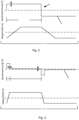
- Fig. 2 and Fig. 3 show possible designs of the operating signal.
- the regulator circuit 10 is configured to regulate one of the operating signal parameters of the operating signal such that a function dependent on the self-induction value of the self-induction and the coil current value of the coil current does not deviate from a predetermined first setpoint.
- the regulator circuit 10 is preferably configured to regulate one of the operating signal parameters such that a product of the self-induction value and the coil current value does not deviate from a predetermined first setpoint.
- the first voltage and the duration of the second time sub-interval are regulated such that a variable dependent on the first voltage and the duration of the second time sub-interval does not deviate from a second setpoint. If a deviation occurs - due to magnetic interference fields or temperature influences - the two control parameters are adjusted until the deviation is minimal again.
- the Fig. 2 shows a first embodiment of the operating signal and the correspondingly generated magnetic field by the coil.
- the operating signal comprises a voltage with a time-varying characteristic 12, which is divided into time intervals t .
- the sign of the applied voltage changes in successive time intervals t .
- Fig. 2 The operating signal shown comprises time intervals t , each of which has a first time sub-interval t hold , in which a constant first voltage U hold is applied to the coil over the entire duration of the first time sub-interval t hold .
- the measured voltage induced for determining the flow velocity-dependent measured variable is determined in the first time sub-interval t hold .
- the controller circuit is set up to regulate the first voltage U hold of a time interval t such that a function dependent on a self-induction value of the self-induction L and a coil current value of the coil current I , in particular a function dependent on a product of the two aforementioned values, does not deviate from a predetermined first setpoint value.
- the first voltage U hold is a time-variable and controllable variable. The increase in the coil current is characterized by a time constant, which can be determined via a measuring circuit. The first voltage U hold can be controlled in such a way that a variable dependent on the product of the time constant and the first voltage U hold does not deviate from a predetermined second setpoint.
- the Fig. 3 shows a second embodiment of the operating signal and the magnetic field generated by the device for generating the magnetic field.
- the operating signal comprises a voltage with a time-varying profile 12, which is divided into time intervals t .
- the sign of the applied voltage changes in successive time intervals t.
- Fig. 2 The operating signal shown comprises time intervals t, each of which has a first time subinterval t hold , in which a constant first voltage U hold is applied to the coil for the entire duration of the first time interval t hold .
- the measured voltage induced for determining the flow velocity-dependent measured variable is determined in the first time interval t hold .
- the time intervals t each have a second time interval t shot in which a second voltage U shot is applied to the coil, in particular one that is constant for the entire duration of the second time interval t shot.
- the second voltage U shot is greater than the first voltage U hold .
- the first time interval t hold follows the second time interval t shot .
- the duration of the second time interval t shot is shorter than the duration of the first time interval t hold .
- the duration of the second time interval t shot is variable over time and controllable. The same applies to the first voltage U hold .
- the first voltage U hold and the second voltage U shot can be set such that a ratio between the first voltage U hold and the second voltage U shot is constant over the entire curve 12. This means that by controlling the first voltage U hold the second voltage U shot is automatically adjusted proportionally to the change. Alternatively the second voltage U shot can assume a constant value over the entire curve 12.
- the duration of the second time interval t shot is controlled such that a determined value of a variable dependent on a test variable assumes a test setpoint within the duration of the second time interval t shot
- the variable can be, for example, a sum or an integral of the measured values of the test variable for a predetermined time period.
- the two control parameters are controlled such that a function dependent on the product of the first voltage U hold and the duration of the second time interval t shot does not deviate from a predetermined second setpoint.
- the function dependent on the first voltage U hold is inversely proportional to the duration of the second time interval t shot .
- the test variable can be a measured value of the coil current, a time profile of a coil current, and/or a variable dependent on it.
- the regulator circuit is set up to change the duration of the second time sub-interval t shot such that the deviation is smaller in a subsequent time interval t N+M , where M ⁇ 1.
- the regulator circuit is set up to change the first voltage U hold such that the deviation from a setpoint in a subsequent time interval t N+M is smaller, where M ⁇ 1.
- the regulator circuit can be set up to regulate further variables and/or functions.
- a measuring circuit is set up to determine a maximum coil current value I max in the first time sub-interval t hold and the duration of the second time sub-interval t shot and the function dependent on the first voltage U hold are controlled in such a way that a control function does not deviate from a predetermined second setpoint value, wherein the control function depends on a product of the duration of the second time sub-interval t shot and the function dependent on the first voltage U hold and the maximum coil current value I max .
- the regulator circuit can be configured to regulate at least one of the operating signal parameters such that a coil current value I hold determined from a quotient of the maximum coil current value I max and a coil current value I hold determined during the first time subinterval t hold is constant over the operating signal.
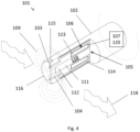
- a flow measuring probe 101 comprises a generally circular cylindrical housing 102 having a predetermined outer diameter. This housing is adapted to the diameter of a bore located in a wall of a Fig. 4 not shown, into which the flow measuring probe 101 is inserted in a fluid-tight manner.
- a medium to be measured flows in the pipeline, into which the flow measuring probe 101 is immersed practically perpendicular to the flow direction of the medium, which is indicated by the wavy arrows 118.
- a front end 116 of the housing 102 which projects into the medium, is sealed in a fluid-tight manner by a front body 115 made of insulating material.
- a magnetic field 109 can be generated that extends through the end section into the medium.
- a coil core 111 which is arranged in the housing 102 and consists at least partially of a soft magnetic material, ends at or near the end section 116.
- a field return body 114 which encloses the coil arrangement 106 and the coil core 111, is designed to return the magnetic field 109 extending from the end section into the housing 102.
- the coil core 111, the pole piece 112, and the field return body 114 are each field guide bodies 110, which together form a field guide arrangement 105.
- a first and a second measuring electrode 103, 104 which form a galvanic contact with the medium to be guided, form the device for detecting a measuring voltage induced in the medium and are arranged in the front body 115 and, like the outer walls of the housing, contact the medium.
- an electrical current induced by Faraday's law of induction can be measured.
- Voltage can be tapped using a measuring and/or evaluation unit. This is maximum when the flow measuring probe 101 is installed in the pipeline in such a way that a plane spanned by a straight line intersecting the two measuring electrodes 103, 104 and a longitudinal axis of the flow measuring probe runs perpendicular to the flow direction 118 or longitudinal axis of the pipeline.
- An operating circuit 107 is electrically connected to the coil arrangement 106, in particular to the coil 113, and is configured to impress a clocked operating signal onto the coil 113 in order to thereby generate a clocked magnetic field 109.
- the controller circuit 120 is configured to regulate at least one of the operating signal parameters of the operating signal in such a way that a function dependent on a self-induction value of the self-induction and a coil current value of the coil current does not deviate from a predetermined setpoint.
- the function dependent on the first voltage U hold and the duration of the second time interval t shot are controlled in such a way that both behave inversely proportional to each other.
Landscapes
- Physics & Mathematics (AREA)
- Electromagnetism (AREA)
- Fluid Mechanics (AREA)
- General Physics & Mathematics (AREA)
- Engineering & Computer Science (AREA)
- Power Engineering (AREA)
- Measuring Volume Flow (AREA)
Applications Claiming Priority (3)
| Application Number | Priority Date | Filing Date | Title |
|---|---|---|---|
| DE102020114517.9A DE102020114517A1 (de) | 2020-05-29 | 2020-05-29 | Magnetisch-induktive Durchflussmessvorrichtung |
| EP21722167.0A EP4158284B1 (fr) | 2020-05-29 | 2021-04-23 | Dispositif de mesure de flux magnéto-inductif |
| PCT/EP2021/060734 WO2021239352A1 (fr) | 2020-05-29 | 2021-04-23 | Dispositif de mesure de flux magnéto-inductif |
Related Parent Applications (2)
| Application Number | Title | Priority Date | Filing Date |
|---|---|---|---|
| EP21722167.0A Division EP4158284B1 (fr) | 2020-05-29 | 2021-04-23 | Dispositif de mesure de flux magnéto-inductif |
| EP21722167.0A Division-Into EP4158284B1 (fr) | 2020-05-29 | 2021-04-23 | Dispositif de mesure de flux magnéto-inductif |
Publications (2)
| Publication Number | Publication Date |
|---|---|
| EP4556864A2 true EP4556864A2 (fr) | 2025-05-21 |
| EP4556864A3 EP4556864A3 (fr) | 2025-08-13 |
Family
ID=75728826
Family Applications (2)
| Application Number | Title | Priority Date | Filing Date |
|---|---|---|---|
| EP25160691.9A Pending EP4556864A3 (fr) | 2020-05-29 | 2021-04-23 | Débitmètre magnéto-inductif |
| EP21722167.0A Active EP4158284B1 (fr) | 2020-05-29 | 2021-04-23 | Dispositif de mesure de flux magnéto-inductif |
Family Applications After (1)
| Application Number | Title | Priority Date | Filing Date |
|---|---|---|---|
| EP21722167.0A Active EP4158284B1 (fr) | 2020-05-29 | 2021-04-23 | Dispositif de mesure de flux magnéto-inductif |
Country Status (5)
| Country | Link |
|---|---|
| US (1) | US12332096B2 (fr) |
| EP (2) | EP4556864A3 (fr) |
| CN (1) | CN115698647A (fr) |
| DE (1) | DE102020114517A1 (fr) |
| WO (1) | WO2021239352A1 (fr) |
Families Citing this family (8)
| Publication number | Priority date | Publication date | Assignee | Title |
|---|---|---|---|---|
| DE102021118264A1 (de) | 2021-07-14 | 2023-01-19 | Endress+Hauser Flowtec Ag | Magnetisch-induktive Durchflussmessvorrichtung |
| DE102021131692A1 (de) | 2021-12-01 | 2023-06-01 | Endress + Hauser Flowtec Ag | Magnetisch-induktive Durchflussmessvorrichtung |
| DE102021131696A1 (de) | 2021-12-01 | 2023-06-01 | Endress+Hauser Flowtec Ag | Verfahren zum Betreiben einer magnetisch-induktiven Durchflussmessvorrichtung |
| CN114527334B (zh) * | 2021-12-30 | 2025-03-04 | 江苏宜海新能源材料科技有限公司 | 一种基于电位差法测定磁场强度的装置 |
| DE102022115271B3 (de) | 2022-06-20 | 2023-11-02 | Krohne Messtechnik Gmbh | Magnetfeldgenerator für ein magnetisch-induktives Durchflussmessgerät, Verfahren zum Betreiben eines solchen, magnetisch-induktives Durchflussmessgerät und Verfahren zum Betreiben eines solchen |
| DE102022129905A1 (de) * | 2022-11-11 | 2024-05-16 | Endress+Hauser Flowtec Ag | Verfahren zum Betreiben eines magnetisch-induktiven Durchflussmessvorrichtung |
| DE102022134361A1 (de) * | 2022-12-21 | 2024-06-27 | Endress+Hauser Flowtec Ag | Vorrichtung zum Bereitstellen eines Erregungsstroms an einem magnetisch-induktiven Durchflussmessgerät und magnetisch-induktives Durchflussmessgerät |
| DE102024123798A1 (de) * | 2024-08-20 | 2026-02-26 | Endress+Hauser Flowtec Ag | Magnetisch-induktives Durchflussmessgerät |
Citations (1)
| Publication number | Priority date | Publication date | Assignee | Title |
|---|---|---|---|---|
| WO2014001026A1 (fr) | 2012-06-28 | 2014-01-03 | Endress+Hauser Flowtec Ag | Procédé de commande du courant circulant dans la bobine d'un débitmètre magnéto-inductif |
Family Cites Families (13)
| Publication number | Priority date | Publication date | Assignee | Title |
|---|---|---|---|---|
| DE19621132A1 (de) * | 1996-05-24 | 1997-11-27 | Bailey Fischer & Porter Gmbh | Verfahren und Vorrichtung zur magnetisch-induktiven Durchflußmessung |
| DE59703805D1 (de) | 1997-07-17 | 2001-07-19 | Flowtec Ag | Magnetisch-induktive Strömungssonde |
| GB2378761B (en) * | 2001-04-25 | 2005-11-30 | Abb Metering Ltd | Flow meter |
| US7260486B2 (en) | 2004-09-22 | 2007-08-21 | Endress + Hauser Flowtec Ag | Method for operating and/or reviewing a magneto-inductive flow meter |
| DE102004046238A1 (de) * | 2004-09-22 | 2006-03-23 | Endress + Hauser Flowtec Ag | Magnetisch-induktives Durchflussmessgerät |
| DE102005031665A1 (de) * | 2005-07-05 | 2007-01-11 | Endress + Hauser Flowtec Ag | Verfahren zur Bestimmung des Arbeitspunktes eines magnetisch-induktiven Durchflussmessgeräts |
| DE102006016564A1 (de) * | 2006-04-06 | 2007-10-11 | Endress + Hauser Flowtec Ag | Vorrichtung zum Bestimmen des Volumen- oder Massestroms eines Mediums |
| DE102013112373A1 (de) | 2013-11-11 | 2015-05-13 | Endress + Hauser Flowtec Ag | Verfahren zum Betrieb einer magnetisch-induktiven Messeinrichtung |
| DE102014111047B4 (de) * | 2014-08-04 | 2016-02-11 | Endress+Hauser Flowtec Ag | Magnetisch-induktives Durchflussmessgerät mit mehreren Messelektrodenpaaren und unterschiedlichen Messrohrquerschnitten und Verfahren zur Messung des Durchflusses |
| DE102015116771B4 (de) | 2015-10-02 | 2021-07-01 | Krohne Messtechnik Gmbh | Verfahren zum Einstellen einer konstanten Magnetfeldstärke eines Magnetfelds bei einem magnetisch-induktiven Durchflussmessgerät und diesbezügliches magnetisch-induktives Durchflussmessgerät |
| US9784603B2 (en) * | 2016-02-17 | 2017-10-10 | Invensys Systems, Inc. | Electromagnetic flowmeter empty pipe detection system |
| DE102016112742A1 (de) * | 2016-07-12 | 2018-01-18 | Endress+Hauser Flowtec Ag | Verfahren zum Messen der Durchflussgeschwindigkeit oder des Volumendurchflusses eines Mediums mittels eines magnetisch-induktiven Durchflussmessgeräts und ein magnetisch-induktives Durchflussmessgerät |
| DE102016122495B4 (de) * | 2016-11-22 | 2022-03-17 | Endress + Hauser Flowtec Ag | Verfahren zum Betreiben eines magnetisch-induktiven Durchflussmessgeräts |
-
2020
- 2020-05-29 DE DE102020114517.9A patent/DE102020114517A1/de active Pending
-
2021
- 2021-04-23 EP EP25160691.9A patent/EP4556864A3/fr active Pending
- 2021-04-23 US US18/000,039 patent/US12332096B2/en active Active
- 2021-04-23 EP EP21722167.0A patent/EP4158284B1/fr active Active
- 2021-04-23 WO PCT/EP2021/060734 patent/WO2021239352A1/fr not_active Ceased
- 2021-04-23 CN CN202180037059.6A patent/CN115698647A/zh active Pending
Patent Citations (1)
| Publication number | Priority date | Publication date | Assignee | Title |
|---|---|---|---|---|
| WO2014001026A1 (fr) | 2012-06-28 | 2014-01-03 | Endress+Hauser Flowtec Ag | Procédé de commande du courant circulant dans la bobine d'un débitmètre magnéto-inductif |
Also Published As
| Publication number | Publication date |
|---|---|
| US12332096B2 (en) | 2025-06-17 |
| WO2021239352A1 (fr) | 2021-12-02 |
| EP4158284A1 (fr) | 2023-04-05 |
| CN115698647A (zh) | 2023-02-03 |
| DE102020114517A1 (de) | 2021-12-02 |
| EP4158284B1 (fr) | 2025-06-04 |
| US20230204396A1 (en) | 2023-06-29 |
| EP4556864A3 (fr) | 2025-08-13 |
Similar Documents
| Publication | Publication Date | Title |
|---|---|---|
| EP4158284B1 (fr) | Dispositif de mesure de flux magnéto-inductif | |
| WO2023099277A1 (fr) | Dispositif de mesure de débit magnéto-inductif | |
| EP1792144B1 (fr) | Procede de controle d'un debitmetre magneto-inductif | |
| EP4370876B1 (fr) | Dispositif de mesure de débit magnéto-inductif | |
| WO2016041723A1 (fr) | Débitmètre à induction magnétique pourvu d'un système magnétique à quatre bobines | |
| DE102013112373A1 (de) | Verfahren zum Betrieb einer magnetisch-induktiven Messeinrichtung | |
| EP1431716A1 (fr) | Débitmètre électromagnétique | |
| EP1893951B1 (fr) | Appareil de mesure de debit a induction magnetique | |
| DE102020114515A1 (de) | Magnetisch-induktive Durchflussmessvorrichtung | |
| EP4070043B1 (fr) | Procédé de mise en oeuvre d'un débitmètre magnéto-inductif et débitmètre magnéto-inductif | |
| WO2023099276A1 (fr) | Débitmètre à induction magnétique | |
| EP4441468A1 (fr) | Procédé pour le fonctionnement d'un débitmètre magnéto-inductif | |
| WO2021110437A1 (fr) | Débitmètre magnéto-inductif | |
| EP4004496B1 (fr) | Débitmètre à induction magnétique et procédé de fonctionnement d'un débitmètre à induction magnétique | |
| WO2024099620A1 (fr) | Procédé pour faire fonctionner un débitmètre magnéto-inductif | |
| WO2024041811A1 (fr) | Procédé de détermination d'une grandeur de mesure dépendant de la vitesse d'écoulement | |
| DE102021131692A1 (de) | Magnetisch-induktive Durchflussmessvorrichtung | |
| WO2024041812A1 (fr) | Procédé de détermination de fonction de correction | |
| EP4639100A1 (fr) | Débitmètre magnéto-inductif |
Legal Events
| Date | Code | Title | Description |
|---|---|---|---|
| PUAI | Public reference made under article 153(3) epc to a published international application that has entered the european phase |
Free format text: ORIGINAL CODE: 0009012 |
|
| STAA | Information on the status of an ep patent application or granted ep patent |
Free format text: STATUS: THE APPLICATION HAS BEEN PUBLISHED |
|
| AC | Divisional application: reference to earlier application |
Ref document number: 4158284 Country of ref document: EP Kind code of ref document: P |
|
| AK | Designated contracting states |
Kind code of ref document: A2 Designated state(s): AL AT BE BG CH CY CZ DE DK EE ES FI FR GB GR HR HU IE IS IT LI LT LU LV MC MK MT NL NO PL PT RO RS SE SI SK SM TR |
|
| PUAL | Search report despatched |
Free format text: ORIGINAL CODE: 0009013 |
|
| AK | Designated contracting states |
Kind code of ref document: A3 Designated state(s): AL AT BE BG CH CY CZ DE DK EE ES FI FR GB GR HR HU IE IS IT LI LT LU LV MC MK MT NL NO PL PT RO RS SE SI SK SM TR |
|
| RIC1 | Information provided on ipc code assigned before grant |
Ipc: G01F 1/60 20060101AFI20250707BHEP |
|
| STAA | Information on the status of an ep patent application or granted ep patent |
Free format text: STATUS: REQUEST FOR EXAMINATION WAS MADE |
|
| 17P | Request for examination filed |
Effective date: 20260203 |