EP4556872A1 - Drucksensor und verfahren zu dessen fertigung - Google Patents
Drucksensor und verfahren zu dessen fertigung Download PDFInfo
- Publication number
- EP4556872A1 EP4556872A1 EP24182378.0A EP24182378A EP4556872A1 EP 4556872 A1 EP4556872 A1 EP 4556872A1 EP 24182378 A EP24182378 A EP 24182378A EP 4556872 A1 EP4556872 A1 EP 4556872A1
- Authority
- EP
- European Patent Office
- Prior art keywords
- housing
- sleeve
- stamp
- distal
- pressure sensor
- Prior art date
- Legal status (The legal status is an assumption and is not a legal conclusion. Google has not performed a legal analysis and makes no representation as to the accuracy of the status listed.)
- Pending
Links
Images



Classifications
-
- G—PHYSICS
- G01—MEASURING; TESTING
- G01L—MEASURING FORCE, STRESS, TORQUE, WORK, MECHANICAL POWER, MECHANICAL EFFICIENCY, OR FLUID PRESSURE
- G01L19/00—Details of, or accessories for, apparatus for measuring steady or quasi-steady pressure of a fluent medium insofar as such details or accessories are not special to particular types of pressure gauges
- G01L19/06—Means for preventing overload or deleterious influence of the measured medium on the measuring device or vice versa
- G01L19/0672—Leakage or rupture protection or detection
-
- G—PHYSICS
- G01—MEASURING; TESTING
- G01L—MEASURING FORCE, STRESS, TORQUE, WORK, MECHANICAL POWER, MECHANICAL EFFICIENCY, OR FLUID PRESSURE
- G01L7/00—Measuring the steady or quasi-steady pressure of a fluid or a fluent solid material by mechanical or fluid pressure-sensitive elements
- G01L7/16—Measuring the steady or quasi-steady pressure of a fluid or a fluent solid material by mechanical or fluid pressure-sensitive elements in the form of pistons
- G01L7/163—Measuring the steady or quasi-steady pressure of a fluid or a fluent solid material by mechanical or fluid pressure-sensitive elements in the form of pistons construction or mounting of pistons
-
- G—PHYSICS
- G01—MEASURING; TESTING
- G01L—MEASURING FORCE, STRESS, TORQUE, WORK, MECHANICAL POWER, MECHANICAL EFFICIENCY, OR FLUID PRESSURE
- G01L19/00—Details of, or accessories for, apparatus for measuring steady or quasi-steady pressure of a fluent medium insofar as such details or accessories are not special to particular types of pressure gauges
- G01L19/14—Housings
-
- G—PHYSICS
- G01—MEASURING; TESTING
- G01L—MEASURING FORCE, STRESS, TORQUE, WORK, MECHANICAL POWER, MECHANICAL EFFICIENCY, OR FLUID PRESSURE
- G01L19/00—Details of, or accessories for, apparatus for measuring steady or quasi-steady pressure of a fluent medium insofar as such details or accessories are not special to particular types of pressure gauges
- G01L19/0061—Electrical connection means
-
- G—PHYSICS
- G01—MEASURING; TESTING
- G01L—MEASURING FORCE, STRESS, TORQUE, WORK, MECHANICAL POWER, MECHANICAL EFFICIENCY, OR FLUID PRESSURE
- G01L19/00—Details of, or accessories for, apparatus for measuring steady or quasi-steady pressure of a fluent medium insofar as such details or accessories are not special to particular types of pressure gauges
- G01L19/06—Means for preventing overload or deleterious influence of the measured medium on the measuring device or vice versa
-
- G—PHYSICS
- G01—MEASURING; TESTING
- G01L—MEASURING FORCE, STRESS, TORQUE, WORK, MECHANICAL POWER, MECHANICAL EFFICIENCY, OR FLUID PRESSURE
- G01L19/00—Details of, or accessories for, apparatus for measuring steady or quasi-steady pressure of a fluent medium insofar as such details or accessories are not special to particular types of pressure gauges
- G01L19/14—Housings
- G01L19/142—Multiple part housings
-
- G—PHYSICS
- G01—MEASURING; TESTING
- G01L—MEASURING FORCE, STRESS, TORQUE, WORK, MECHANICAL POWER, MECHANICAL EFFICIENCY, OR FLUID PRESSURE
- G01L23/00—Devices or apparatus for measuring or indicating or recording rapid changes, such as oscillations, in the pressure of steam, gas, or liquid; Indicators for determining work or energy of steam, internal-combustion, or other fluid-pressure engines from the condition of the working fluid
- G01L23/08—Devices or apparatus for measuring or indicating or recording rapid changes, such as oscillations, in the pressure of steam, gas, or liquid; Indicators for determining work or energy of steam, internal-combustion, or other fluid-pressure engines from the condition of the working fluid operated electrically
- G01L23/10—Devices or apparatus for measuring or indicating or recording rapid changes, such as oscillations, in the pressure of steam, gas, or liquid; Indicators for determining work or energy of steam, internal-combustion, or other fluid-pressure engines from the condition of the working fluid operated electrically by pressure-sensitive members of the piezoelectric type
Definitions
- the invention relates to a pressure sensor according to the preamble of claim 1 and a method for its manufacture according to the preamble of claim 11.
- the font WO2006/032152A1 shows a pressure sensor for measuring the pressure prevailing in a pressure chamber of an injection mold or an internal combustion engine.
- the pressure sensor has a housing, a plunger, and a measuring element.
- the housing has an interior housing space in which the plunger and the measuring element are arranged.
- the plunger has a distal plunger end and a proximal plunger end.
- the plunger is operatively connected to the measuring element via the proximal plunger end.
- the pressure sensor can be fastened in a bore in a wall of the pressure chamber via the housing. When the pressure sensor is fastened in the bore, the distal plunger end protrudes from the housing into the pressure chamber.
- the pressure to be measured is transmitted from the distal plunger end to the proximal plunger end and acts on the measuring element.
- the medium in the pressure chamber of an injection mold is a liquid melt of plastic, Metal, etc., or in an internal combustion engine, a fuel-air mixture.
- the medium can have a temperature of several hundred °C and a pressure of several hundred bar.
- the plunger is arranged so that it can move relative to the housing, which is achieved by a gap between the housing and the plunger.
- the document teaches WO2006/032152A1 to arrange a metallic ring membrane in the gap, which ring membrane is attached to the plunger and the housing by a welded connection and seals the gap.
- the welded joint of the annular diaphragm creates a force shunt, through which part of the pressure to be measured passes from the plunger into the housing, thus reducing the sensitivity of the pressure sensor when measuring the pressure.
- the annular diaphragm is designed to be thick to ensure a long service life and then creates a noticeable force shunt.
- the annular diaphragm, which is welded to the housing and plunger, also forms an oscillating system and is excited to vibrate during pressure measurement, which vibrations can distort the pressure measurement.
- the location of the welded joint of the annular diaphragm in the gap between the housing and plunger is difficult to reach with a welding tool, which makes the production of the welded joint complex and expensive.
- a first object of the present invention is to provide a pressure sensor that measures the pressure to be measured with high sensitivity and high accuracy.
- the pressure sensor should also be able to measure high pressures of over 1000 bar with high sensitivity and high accuracy.
- a further object is to demonstrate a method for simple and cost-effective production of the pressure sensor.
- At least one of the objects is achieved by the features of claim 1 or 11.
- the invention relates to a pressure sensor with a housing, a plunger unit and a measuring element; which housing has a housing interior and which plunger unit and which measuring element are arranged in the housing interior; which plunger unit has a distal plunger end and a proximal plunger end, which distal plunger end is arranged on a longitudinal axis of the pressure sensor further away from the measuring element than the proximal plunger end, which distal plunger end protrudes from the housing and which proximal plunger end is operatively connected to the measuring element and transmits a pressure of a medium prevailing outside the housing to the measuring element; wherein the pressure sensor has a sleeve, which sleeve is fastened to the housing; wherein the sleeve and the distal plunger end are spaced from each other by a gap; and wherein the pressure sensor has at least one sealing element, which sealing element seals the gap for the medium to the housing interior by means of sealing compression.
- the invention also relates to a method for manufacturing a pressure sensor, comprising a housing, a stamp unit, and a measuring element; which housing has a housing interior, and which stamp unit and which measuring element are arranged in the housing interior; which stamp unit has a distal stamp end and a proximal stamp end, which distal stamp end is arranged further away from the measuring element on a longitudinal axis of the pressure sensor than the proximal stamp end, and which distal stamp end protrudes from the housing, and which proximal stamp end is operatively connected to the measuring element and transmits a pressure of a medium prevailing outside the housing to the measuring element; wherein, in a first step of the method, the housing and a sensor unit with a stamp unit and a measuring element are provided, and the housing is pushed along the longitudinal axis over the stamp unit and placed onto the sensor unit; wherein, in a second step of the method, at least one sealing element is provided, and the sealing element is pushed along the longitudinal axis over the distal stamp
- a sleeve is provided and is pushed along the longitudinal axis over the distal end of the punch and placed onto the sealing element and the housing, which sleeve and which distal end of the punch are spaced apart from each other by a gap, and which sealing element seals the gap for the medium to the housing interior by means of a sealing compression.
- the invention for sealing the gap between the plunger and the housing prevents force shunts.
- the gap is sealed by compression, which transfers the pressure to be measured from the plunger almost completely to the measuring element, achieving high sensitivity and high accuracy in the pressure measurement.
- the sealing element is toroidal and consists of elastically sealing material such as elastomer, in particular fluoroelastomer or perfluoroelastomer, or rubber, in particular acrylonitrile butadiene rubber.
- the sealing element made of elastic material does not constitute an oscillating system that can be excited to oscillate during pressure measurement, which could distort the pressure measurement. Avoiding such oscillations enables pressure measurement with high sensitivity and accuracy.
- a groove is formed around the sealing element radially on the inside of the sleeve and on the housing with respect to the longitudinal axis.
- the groove has a plurality of groove walls; wherein the groove walls exert a pre-compression on the sealing element arranged in the groove; and wherein the pressure in the gap acts as a compression pressure on the sealing element in addition to the pre-compression, which pre-compression and which compression pressure form the sealing pressure.
- the two-stage sealing consisting of pre-pressing and compression, ensures that even at low pressure, no medium penetrates the gap into the housing interior and damages or destroys the measuring element.
- the production of the groove that pre-loads the sealing element is simple and cost-effective.
- the groove is rectangular or triangular or trapezoidal or round or semicircular in cross section.
- the punch unit comprises a preload sleeve and a preload body; wherein the proximal punch end merges into the preload sleeve; wherein the preload sleeve encloses a preload sleeve space, in which preload sleeve space the measuring element is arranged; wherein an end of the preload sleeve facing away from the proximal punch end is fastened to the preload body via a material-to-material preload sleeve-preload body connection; and wherein the measuring element is arranged on the longitudinal axis between the proximal punch end and the preload body under mechanical preload.
- This refinement prevents mechanical stresses caused by the pressure sensor's mounting in the pressure chamber wall from transferring from the housing to the measuring element and potentially distorting the pressure measurement. Preventing the transmission of such mechanical stresses increases the sensitivity and accuracy of the pressure measurement.
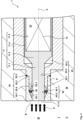
- the Fig. 1 to 6 show cross sections through several embodiments of a part of a pressure sensor 1 according to the invention.
- the pressure sensor 1 has the function of measuring the pressure P of a medium M in a pressure chamber C.
- the pressure chamber C can be located in an injection mold, in an internal combustion engine, etc.
- the medium M is a liquid melt of plastic, metal, etc.
- the medium M is a fuel-air mixture.
- the medium M can have a temperature T of several hundred °C and a pressure P of several thousand bar.
- the temperature T is in the range from 100 °C to 500 °C and the pressure P is in the range from 50 bar to 5000 bar.
- the pressure P to be measured is in the Fig. 1 to 6 shown schematically as black arrows.
- the pressure sensor 1 has a sensor unit 10.
- the sensor unit 10 has the function of accommodating a measuring element 12.
- the sensor unit 10 is in the Fig. 1 to 6 only partially shown, but the sensor unit 10 is shown in cross section of the Fig. 7 and in the exploded view of the Fig. 8 fully presented.
- the pressure sensor 1 has a longitudinal axis A.
- the Fig. 1 to 8 show the pressure sensor 1 along the longitudinal axis A.
- the pressure sensor 1 has a housing 20.
- the housing 20 has the function of securing the sensor unit 10 in a bore H of a wall W of the pressure chamber C.
- the fastening of the pressure sensor 1 via the housing 20 in the bore H can be a screw connection.
- the screw connection is not shown in the figure.
- the housing 20 is hollow cylindrical and consists of mechanically resistant material such as pure metals, nickel alloys, Cobalt alloys, iron alloys, etc. How well in Fig. 8 As can be seen, the housing 20 has a distal housing end 20.1 and a proximal housing end 20.2, which distal housing end 20.1 is arranged further away from the measuring element 12 on the longitudinal axis A than the proximal housing end 20.2.
- the housing 20 has a housing interior 20.3. With respect to the longitudinal axis A, the housing 20 radially encloses the housing interior 20.3.
- the sensor unit 10 is arranged in the housing interior 20.3.
- the sensor unit 10 has a stamp unit 11.
- the stamp unit 11 has the primary function of receiving the pressure P to be measured and transmitting it to the measuring element 12.
- the stamp unit 11 has a distal stamp end 11.1, a proximal stamp end 11.2, and a preload sleeve 11.3.
- the stamp unit 11 is made of mechanically resistant material such as pure metals, nickel alloys, cobalt alloys, iron alloys, etc.
- the distal stamp end 11.1, the proximal stamp end 11.2, and the preload sleeve 11.3 are integral.
- the distal stamp end 11.1 and the proximal stamp end 11.2 are cylindrical and merge into one another.
- the proximal stamp end 11.2 merges into the preload sleeve 11.3.
- the preload sleeve 11.3 is hollow cylindrical and encloses a preload sleeve chamber 11.4.
- the measuring element 12 is arranged in the preload sleeve space 11.4.
- the distal end of the punch 11.1 is arranged further away from the measuring element 12 on the longitudinal axis A than the proximal end of the punch 11.2.
- the distal end of the punch 11.1 has The end has a front surface, which is also called the pressure receiving surface 11.11.
- the pressure P to be measured acts via the pressure receiving surface 11.11 on the distal plunger end 11.1 and is transferred from the distal plunger end 11.1 to the proximal plunger end 11.2. From the proximal plunger end 11.2, the pressure P to be measured then acts directly on the measuring element 12.
- the plunger unit 11 has the further function of preventing mechanical stresses originating from the fastening of the pressure sensor 1 in the bore H of the wall W of the pressure chamber C from passing from the housing 20 to the measuring element 12, as such mechanical stresses can falsify the measurement of the pressure P.
- the plunger unit 11 has a preload body 11.5.
- the preload body 11.5 is hollow cylindrical.
- An end of the preload sleeve 11.3 facing away from the proximal plunger end 11.2 is fastened to the preload body 11.5. Due to this fastening, the measuring element 12 is arranged under mechanical preload on the longitudinal axis A between the proximal plunger end 11.2 and the preload body 11.5.
- mechanical preload indicates that the mechanical preload is formed before the actual measurement of the pressure P.
- the amount of mechanical prestress is at least one decimal order of magnitude greater than possible mechanical stresses from the fastening of the pressure sensor 1 via the housing 20 in the wall W of the pressure chamber C.
- the preload sleeve 11.3 is thin-walled with a wall thickness of less than or equal to 0.1 mm.
- the thin-walled preload sleeve 11.3 enables great mobility of the plunger 11 and thus a high sensitivity of the pressure sensor 1.
- the aim is to prevent the penetration of medium M with high temperature T and high pressure P through the gap 30.4 into the housing interior 20.3.
- the medium M is a liquid melt, which would harden in the housing interior 20.3 and thus prevent the mobility of the plunger 11.
- the medium M is a fuel-air mixture, which is chemically aggressive and would corrode the preload sleeve 11.3 in the housing interior 20.3 and thus damage or destroy it.
- the measuring element 12 has the function of generating a measurement signal S for the pressure P to be measured.
- the measuring element 12 can be a piezoelectric measuring element, a piezoresistive measuring element, a strain gauge, etc.
- a size of the measurement signal S is proportional to the measured pressure P.
- the sensor unit 10 also includes an electrode assembly 13, a socket unit 14, a socket contact 15 and an insulating body 16.
- the socket unit 14 has the function of accommodating the electrode arrangement 13, the socket contact 15 and the insulating body 16.
- the socket unit 14 has a hollow cylindrical socket housing made of mechanically resistant material such as pure metals, nickel alloys, cobalt alloys, iron alloys, etc.
- the socket housing is connected via a socket housing-preloading body connection on the side of the preload body 11.5 facing away from the measuring element 12.
- the socket unit 14 has a socket chamber.
- the electrode assembly 13, the socket contact 15, and the insulation body 16 are arranged in the socket chamber.
- the electrode arrangement 13 has the function of conducting the measurement signal S from the measuring element 12 to the socket contact 15.
- the electrode arrangement 13 is cylindrical and made of electrically conductive material such as copper, silver, gold, etc.
- the electrode arrangement 13 is arranged at the end of the socket unit 14 facing the measuring element 12 and extends from the socket space into the preload sleeve space 11.4.
- the electrode arrangement 13 is electrically connected to the measuring element 12.
- the electrode arrangement 1 conducts the measurement signal S from the measuring element 12 along the longitudinal axis A to the socket contact 15.
- the socket contact 15 serves to provide the measurement signal S outside the socket unit 14.
- the socket contact 15 is cylindrical and made of an electrically conductive material such as copper, silver, gold, etc.
- the socket contact 15 is arranged at the end of the socket unit 14 facing away from the measuring element 12.
- the electrode arrangement 13 and the socket contact 15 are electrically connected to one another.
- the insulating body 16 has the function of electrically insulating the electrode arrangement 13 and the socket contact 15. to insulate against the socket housing.
- the insulating body 16 is hollow-cylindrical and consists of electrically insulating and mechanically rigid material such as ceramic, Al 2 O 3 ceramic, sapphire, etc. With respect to the longitudinal axis A, the insulating body 16 is arranged radially outside the electrode arrangement 13 and the socket contact 15.
- the plunger unit 11 and the measuring element 12 are arranged as components of the sensor unit 10 in the housing interior 20.3.
- the distal plunger end 11.1 protrudes from the housing 20.
- the distal housing end 20.1 has a housing opening 20.4.
- the distal plunger end 11.1 protrudes through the housing opening 20.4 to the pressure chamber C.
- the pressure sensor 1 has a sleeve 30.
- the sleeve 30 has the function of accommodating at least one sealing element 40.
- the sleeve 30 is hollow-cylindrical and consists of mechanically resistant material such as pure metals, nickel alloys, cobalt alloys, iron alloys, etc.
- the sleeve 30 has a distal sleeve end 30.1 and a proximal sleeve end 30.2, the distal sleeve end 30.1 being arranged further away from the measuring element 12 along the longitudinal axis A than the proximal sleeve end 30.2.
- the distal plunger end 11.1 extends to the distal sleeve end 30.1.
- the pressure receiving surface 11.11 and the distal sleeve end 30.1 lie in a pressure receiving plane B perpendicular to the longitudinal axis A.
- the distal plunger end 11.1 and the distal sleeve end 30.1 can be specifically adapted to the surface geometry of the wall W of the pressure chamber C by cutting them to length.
- the distal plunger end 11.1 and the distal sleeve end 30.1 can thus be cut to length to a surface geometry of the wall W of the pressure chamber C that runs obliquely or curved to the longitudinal axis A.
- the sleeve 30 is attached to the housing 20.
- the sleeve 30 is attached to the proximal sleeve end 30.2 via a sleeve-housing connection 30.3 at the distal housing end 20.1.
- the sleeve-housing connection 30.3 is arranged radially outwardly at the proximal sleeve end 30.2 and at the distal housing end 20.1.
- the sleeve-housing connection 30.3 is made by welding, soldering, screwing, pressing, gluing, etc. In the embodiments illustrated in the figures, the sleeve-housing connection 30.3 is a welded connection.
- the sleeve 30 partially surrounds the distal end 11.1 of the punch. With respect to the longitudinal axis A, the sleeve 30 surrounds the distal end 11.1 of the punch radially on the outside.
- the distal end 11.1 of the punch has a lateral surface
- the sleeve 30 encloses the outer surface of the distal plunger end 11.1 radially on the outside at an angle of 360°.
- the sleeve 30 and the distal end of the punch 11.1 are spaced apart by a gap 30.4.
- the gap 30.4 has a width of less than or equal to 0.1 mm in the radial direction perpendicular to the longitudinal axis A.
- the sleeve 30 and housing 20 form at least one groove 50.
- the groove 50 serves to accommodate the sealing element 40.
- the groove 50 is arranged in the region of the proximal sleeve end 30.2 and the distal housing end 20.1.
- the sealing element 40 is arranged in the groove 50.
- the sleeve 30 can have a length of several cm along the longitudinal axis A.
- the groove 50 and the sealing element 40 are then located at a relatively large distance of several cm from the pressure chamber C. This has the advantage that, when the medium M has a high temperature T, the sealing element 40 is not exposed to the high temperature T of the medium M during operation of the pressure sensor 1, since the temperature T in the wall W and thus also in the sleeve 30 decreases with increasing distance from the pressure chamber C.
- the sleeve 30 can also have a length of only a few mm.
- the groove 50 and the sealing element 40 are then located at a relatively short distance of a few mm from the pressure chamber C. This has the advantage that a medium M with low viscosity cannot penetrate far into the gap 30.4 along the longitudinal axis A before it encounters the sealing element 40.
- the groove 50 is arranged radially inwardly on the sleeve 30 and the housing 20 with respect to the longitudinal axis A.
- the groove 50 is annular.
- the groove 50 has a plurality of groove walls 50.1, 50.2, 50.3. At least one of the groove walls 50.1, 50.2, 50.3 is part of the proximal sleeve end 30.2. At least one of the groove walls 50.1, 50.2, 50.3 is part of the distal housing end 20.1.
- the groove 50 is rectangular in cross-section and has three groove walls 50.1, 50.2, 50.3. Of the three groove walls 50.1, 50.2, 50.3, a first groove wall 50.1 and a second groove wall 50.2 are part of the proximal sleeve end 30.2, and a third groove wall 50.3 is part of the distal housing end 20.1.
- the first groove wall 50.1 and the third groove wall 50.3 are straight and arranged at an angle of 90° to the longitudinal axis A; the second groove wall 50.2 is straight and arranged parallel to the longitudinal axis A.
- the groove 50 is triangular in cross-section and has two groove walls 50.1, 50.2. Of the two groove walls 50.1, 50.2, a first groove wall 50.1 is part of the proximal sleeve end 30.2 and a second groove wall 50.2 is part of the distal housing end 20.1.
- the first groove wall 50.1 and the second groove wall 50.2 are arranged obliquely to the longitudinal axis A.
- the first groove wall 50.1 and the second groove wall 50.2 are arranged at an angle of 30° to the longitudinal axis A.
- the two oblique groove walls 50.1, 50.2 allow precise positioning of the sealing element 40 in the groove 50.
- the groove 50 is trapezoidal in cross-section and has three groove walls 50.1, 50.2, 50.3. Of the three groove walls 50.1, 50.2, 50.3, a first groove wall 50.1 and a second groove wall 50.2 are part of the proximal sleeve end 30.2 and a third groove wall 50.3 is part of the distal housing end 20.1.
- the first groove wall 50.1 and the third groove wall 50.3 are arranged obliquely to the longitudinal axis A
- the second groove wall 50.2 is straight and arranged parallel to the longitudinal axis A.
- the first groove wall 50.1 and the third groove wall 50.3 are arranged at an angle of 30° to the longitudinal axis A.
- the groove is round in cross-section and has two groove walls 50.1, 50.2. Of the two groove walls 50.1, 50.2, a first groove wall 50.1 is part of the proximal sleeve end 30.2 and a second groove wall 50.2 is part of the distal housing end 20.1.
- the first groove wall 50.1 is round and curved from the longitudinal axis A into the proximal sleeve end 30.2.
- the curvature preferably has a constant radius.
- the second groove wall 50.2 is round and curved from the longitudinal axis A into the distal housing end 20.1.
- the curvature preferably has a constant radius.
- the two round groove walls 50.1, 50.2 allow precise positioning of the sealing element 40 in the groove 50.
- the groove is semicircular and has three groove walls 50.1, 50.2, 50.3. Of the three groove walls 50.1, 50.2, 50.3, a first groove wall 50.1 and a second groove wall 50.2 Part of the proximal sleeve end 30.2, and a third groove wall 50.3 is part of the distal housing end 20.1.
- the first groove wall 50.1 is round and curved from the longitudinal axis A into the proximal sleeve end 30.2.
- the curvature has a constant radius.
- the second groove wall 50.2 is straight and arranged parallel to the longitudinal axis A.
- the third groove wall 50.3 is straight and arranged at an angle of 90° to the longitudinal axis A.
- the groove is semicircular and has three groove walls 50.1, 50.2, 50.3. Of the three groove walls 50.1, 50.2, 50.3, a first groove wall 50.1 and a second groove wall 50.2 are part of the proximal sleeve end 30.2 and a third groove wall 50.3 is part of the distal housing end 20.1.
- the first groove wall 50.1 is straight and arranged at an angle of 90° to the longitudinal axis A.
- the second groove wall 50.2 is straight and arranged parallel to the longitudinal axis A.
- the third groove wall 50.3 is round and curved from the longitudinal axis A into the distal housing end 20.1.
- the curvature preferably has a constant radius.
- the pressure sensor 1 has at least one sealing element 40.
- the sealing element 40 has the function of sealing the gap 30.4.
- the verb "seal" means that during operation of the pressure sensor 1, no medium M can pass through the gap 30.4 into the housing interior. 20.3.
- the sealing element 40 permanently seals the gap 30.4 at a temperature in the range of 100°C to 500°C and at a pressure P in the range of 50 bar to 5000 bar.
- the sealing element 40 is toroidal and consists of an elastically sealing material such as an elastomer, in particular a fluoroelastomer or perfluoroelastomer, a rubber, in particular an acrylonitrile butadiene rubber, etc.
- the sealing element 40 has a toroidal sealing body 40.1 and a toroidal opening 40.2.
- the toroidal sealing body 40.1 encloses the toroidal opening 40.2.
- the distal plunger end 11.1 protrudes through the toroidal opening 40.2.
- the sealing element 40 is arranged in the groove 50.
- the sealing element 40 seals the gap 30.4 by sealing pressure.
- the sealing pressure can be implemented as an axial sealing pressure along the longitudinal axis A, or as a radial sealing pressure perpendicular to the longitudinal axis A, or as a combination of axial sealing pressure along the longitudinal axis A and radial sealing pressure perpendicular to the longitudinal axis A.
- the sealing element 40 is arranged in the groove 50 with a pre-compression. The pre-compression is exerted on the sealing element 40 by the groove walls 50.1, 50.2, 50.3. In addition to the pre-compression, the pressure P in the gap 30.4 acts as a compressive pressure on the sealing element 40. The sealing pressure is thus formed by the pre-compression and the compressive pressure.
- the person skilled in the art can also use several sealing elements in one groove or in several Arrange grooves. With respect to the longitudinal axis A, the majority of the sealing elements are then arranged one behind the other and seal the gap 30.4 several times.
- the Fig. 9 to 11 show in views three steps of the inventive method for manufacturing the pressure sensor 1.
- the views of the Fig. 9 to 11 show the pressure sensor 1 along a longitudinal axis A of the pressure sensor 1.
- a housing 20 and a sensor unit 10 are provided, and the housing 20 is pushed over the punch unit 11 along the longitudinal axis A and placed onto the sensor unit 10. This moves the punch unit 11 into the housing interior 20.3.
- the distal punch end 11.1 protrudes through the housing opening 20.4.
- the proximal housing end 20.2 sits on the preload body 11.5.
- the housing 20, thus placed onto the preload body 11.5, is fastened to the preload body 11.5 via a housing-preload body connection 20.5.
- the housing-preload body connection 20.5 is arranged radially on the outside of the housing 20 and the preload body 11.5.
- the housing-preloading body connection 20.5 is made by welding, soldering, screwing, etc. In the embodiments shown in the figures, the housing-preloading body connection 20.5 is a welded connection.
- a sealing element 40 is provided and pushed along the longitudinal axis A over the distal stamp end 11.1 and placed on the housing 20.
- the distal The end of the punch 11.1 thus protrudes through the torus opening 40.2.
- a sleeve 30 is provided and pushed along the longitudinal axis A over the distal plunger end 11.1 and placed onto the sealing element 40 and the housing 20.
- the proximal sleeve end 30.2 sits on the distal housing end 20.1.
- the sleeve 30 thus placed onto the housing 20 is fastened to the housing 20 via the sleeve-housing connection 30.3.
- the sealing element 40 is pre-pressed by the attached sleeve 30 and the housing 20.
Landscapes
- Physics & Mathematics (AREA)
- General Physics & Mathematics (AREA)
- Chemical & Material Sciences (AREA)
- Engineering & Computer Science (AREA)
- Combustion & Propulsion (AREA)
- Measuring Fluid Pressure (AREA)
Abstract
Description
- Die Erfindung betrifft einen Drucksensor nach dem Oberbegriff des Anspruches 1 sowie ein Verfahren zu dessen Fertigung nach dem Oberbegriff des Anspruches 11.
- Drucksensoren werden in den unterschiedlichsten technischen Anwendungen eingesetzt. Die Schrift
WO2006/032152A1 zeigt einen Drucksensor zum Messen eines in einem Druckraum eines Spritzgiesswerkzeuges oder eines Verbrennungsmotors herrschenden Druckes. Der Drucksensor weist ein Gehäuse, einen Stempel und ein Messelement auf. Das Gehäuse weist einen Gehäuseinnenraum auf, in welchem Gehäuseinnenraum der Stempel und das Messelement angeordnet sind. Bezüglich des Messelementes weist der Stempel ein distales Stempelende und ein proximales Stempelende auf. Mit dem proximalen Stempelende steht der Stempel mit dem Messelement in Wirkverbindung. Über das Gehäuse lässt sich der Drucksensor in einer Bohrung einer Wand des Druckraumes befestigen. Im in der Bohrung befestigten Zustand des Drucksensors ragt das distale Stempelende aus dem Gehäuse in den Druckraum. Der zu messende Druck wird vom distalen Stempelende auf das proximale Stempelende übertragen und wirkt auf das Messelement. - Das sich im Druckraum befindende Medium ist bei einem Spritzgiesswerkzeug eine flüssige Schmelze aus Kunststoff, Metall, usw. oder bei einem Verbrennungsmotor ein Kraftstoff-Luft-Gemisch. Das Medium kann eine Temperatur von mehreren hundert °C und einen Druck von mehreren hundert bar haben. Für eine hohe Empfindlichkeit des Drucksensors bei der Messung des Druckes, ist der Stempel bezüglich des Gehäuses beweglich angeordnet, was durch einen Spalt zwischen dem Gehäuse und dem Stempel realisiert ist. Und um zu verhindern, dass das Medium durch den Spalt in den Gehäuseinnenraum gelangt und dort das Messelement beschädigt oder zerstört, lehrt die Schrift
WO2006/032152A1 , im Spalt eine metallische Ringmembran anzuordnen, welche Ringmembran am Stempel und am Gehäuse durch eine Schweissverbindung angebracht ist und den Spalt abdichtet. - Die Schweissverbindung der Ringmembran stellt allerdings einen Kraftnebenschluss dar, über welchen Kraftnebenschluss ein Teil des zu messenden Druckes vom Stempel in das Gehäuse gelangt und so die Empfindlichkeit des Drucksensors bei der Messung des Druckes reduziert. Insbesondere bei hohen Drücken von über 1000 bar ist die Ringmembran zur Gewährleistung einer hohen Lebensdauer dick ausgestaltet und bildet dann einen merklichen Kraftnebenschluss. Auch bildet die mit dem Gehäuse und dem Stempel verschweisste Ringmembran ein Schwing-System und wird bei der Druckmessung zu Schwingungen angeregt, welche Schwingungen die Messung des Druckes verfälschen können. Schliesslich ist der Ort der Schweissverbindung der Ringmembran im Spalt zwischen Gehäuse und Stempel mit einem Schweisswerkzeug nur schwer zu erreichen, was die Fertigung der Schweissverbindung aufwändig und teuer macht.
- Eine erste Aufgabe der vorliegenden Erfindung besteht darin, einen Drucksensor bereitzustellen, welcher Drucksensor den zu messenden Druck mit hoher Empfindlichkeit und hoher Genauigkeit misst. Insbesondere soll der Drucksensor auch hohe Drücke von über 1000 bar mit hoher Empfindlichkeit und hoher Genauigkeit messen können. Als weitere Aufgabe soll ein Verfahren zur einfachen und kostengünstigen Fertigung des Drucksensors aufgezeigt werden.
- Zumindest eine der Aufgaben wird durch die Merkmale des Anspruches 1 oder 11 gelöst.
- Die Erfindung betrifft einen Drucksensor mit einem Gehäuse, einer Stempeleinheit und einem Messelement; welches Gehäuse einen Gehäuseinnenraum aufweist und welche Stempeleinheit und welches Messelement im Gehäuseinnenraum angeordnet sind; welche Stempeleinheit ein distales Stempelende und ein proximales Stempelende aufweist, welches distale Stempelende auf einer Längsachse des Drucksensors weiter entfernt als das proximale Stempelende vom Messelement angeordnet ist, welches distale Stempelende aus dem Gehäuse ragt und welches proximale Stempelende mit dem Messelement in Wirkverbindung steht und einen ausserhalb des Gehäuses herrschender Druck eines Mediums auf das Messelement überträgt; wobei der Drucksensor eine Hülse aufweist, welche Hülse am Gehäuse befestigt ist; wobei die Hülse und das distale Stempelende durch einen Spalt voneinander beabstandet sind; und wobei der Drucksensor mindestens ein Dichtelement aufweist, welches Dichtelement den Spalt für das Medium zum Gehäuseinnenraum per Dichtpressung abdichtet.
- Die Erfindung betrifft auch ein Verfahren zur Fertigung eines Drucksensors, mit einem Gehäuse, einer Stempeleinheit und einem Messelement; welches Gehäuse einen Gehäuseinnenraum aufweist und welche Stempeleinheit und welches Messelement im Gehäuseinnenraum angeordnet sind; welche Stempeleinheit ein distales Stempelende und ein proximales Stempelende aufweist, welches distale Stempelende auf einer Längsachse des Drucksensors weiter entfernt als das proximale Stempelende vom Messelement angeordnet ist und welches distale Stempelende aus dem Gehäuse ragt und welches proximale Stempelende mit dem Messelement in Wirkverbindung steht und einen ausserhalb des Gehäuses herrschender Druck eines Mediums auf das Messelement überträgt; wobei in einem ersten Schritt des Verfahrens das Gehäuse und eine Sensoreinheit mit einer Stempeleinheit und einem Messelement bereitgestellt werden, und dass das Gehäuse entlang der Längsachse über die Stempeleinheit geschoben und auf die Sensoreinheit gesetzt wird; wobei in einem zweiten Schritt des Verfahrens mindestens ein Dichtelement bereitgestellt wird, und dass das Dichtelement entlang der Längsachse über das distale Stempelende geschoben und auf das Gehäuse gesetzt wird; und wobei in einem dritten Schritt des Verfahrens eine Hülse bereitgestellt wird und entlang der Längsachse über das distale Stempelende geschoben und auf das Dichtelement und das Gehäuse gesetzt wird, welche Hülse und welches distale Stempelende durch einen Spalt voneinander beabstandet sind, und welches Dichtelement den Spalt für das Medium zum Gehäuseinnenraum per Dichtpressung abdichtet.
- Im Unterschied zur Lehre der Schrift
WO2006/032152A1 vermeidet die Erfindung zur Abdichtung des Spaltes zwischen Stempel und Gehäuse einen Kraftnebenschluss. Die Abdichtung des Spaltes erfolgt per Dichtpressung, wodurch der zu messende Druck vom Stempel weitgehend vollständig auf das Messelement übertragen wird und eine hohe Empfindlichkeit und hohe Genauigkeit bei der Messung des Druckes erzielt wird. - Vorteilhafte Weiterbildungen des Erfindungsgegenstandes werden in den abhängigen Ansprüchen beansprucht.
- In einer vorteilhaften Weiterbildung ist das Dichtelement torusförmig und besteht aus elastisch dichtendem Material wie Elastomer, insbesondere aus Fluorelastomer oder aus Perfluorelastomer, oder aus Kautschuk, insbesondere aus Acrylnitril-Butadien-Kautschuk.
- Im weiteren Unterschied zur Lehre der Schrift
WO2006/032152A1 stellt das Dichtelement aus elastischem Material kein Schwing-System dar, welches bei der Druckmessung zu Schwingungen anregbar ist, welche Schwingungen die Messung des Druckes verfälschen können. Die Vermeidung solcher Schwingungen ermöglicht die Messung des Druckes mit hoher Empfindlichkeit und hoher Genauigkeit. - In einer weiteren vorteilhaften Weiterbildung wird im dritten Schritt des Verfahrens durch das Aufsetzen der Hülse auf das Gehäuse um das Dichtelement bezüglich der Längsachse radial innenseitig an der Hülse und am Gehäuse eine Nut gebildet.
- Eine solche Fertigung einer Nut zur Beherbergung des Dichtelementes ist einfach und kostengünstig.
- In einer weiteren vorteilhaften Weiterbildung weist die Nut mehrere Nutenwände auf; wobei die Nutenwände eine Vorpressung auf das in der Nut angeordnete Dichtelement ausüben; und wobei der Druck im Spalt zusätzlich zur Vorpressung als Druckpressung auf das Dichtelement wirkt, welche Vorpressung und welche Druckpressung die Dichtpressung bilden.
- Durch die zweistufige Abdichtung durch eine Vorpressung und eine Druckpressung wird sichergestellt, dass auch bei niedrigem Druck kein Medium durch den Spalt in den Gehäuseinnenraum gelangt und dort das Messelement beschädigt oder zerstört. Die Fertigung der das Dichtelement vorspannenden Nut ist einfach und kostengünstig.
- In noch einer weiteren vorteilhaften Weiterbildung ist die Nut im Querschnitt rechteckig oder dreieckig oder trapezförmig oder rund oder halbrund.
- Durch diese im Querschnitt unterschiedlichen Geometrien lässt sich die Grösse der von den Nutenwänden auf das torusförmige Dichtelement ausgeübten Vorpressung einstellen. Für ein Dichtelement mit gegebenen Abmessungen wird mit bezüglich der Längsachse schrägen Nutenwänden oder mit bezüglich der Längsachse in die Hülse oder das Gehäuse gewölbten runden Nutenwänden im Vergleich zu bezüglich der Längsachse geraden Nutenwänden eine höhere Vorpressung erzielt. Somit lässt sich der Drucksensor auch bei hohen Drücken von über 1000 bar betreiben, ohne dass Medium durch den Spalt in den Gehäuseinnenraum gelangt. Die Fertigung der unterschiedlichen Geometrien der Nut ist einfach und kostengünstig.
- In noch einer weiteren vorteilhaften Weiterbildung weist die Stempeleinheit eine Vorspannhülse und einen Vorspannkörper auf; wobei das proximale Stempelende in die Vorspannhülse übergeht; wobei die Vorspannhülse einen Vorspannhülsenraum umschliesst, in welchem Vorspannhülsenraum das Messelement angeordnet ist; wobei ein vom proximalen Stempelende abgewandtes Ende der Vorspannhülse über eine stoffschlüssige Vorspannhülse-Vorspannkörper-Verbindung am Vorspannkörper befestigt ist; und wobei das Messelement auf der Längsachse zwischen dem proximalen Stempelende und dem Vorspannkörper unter mechanischer Vorspannung angeordnet ist.
- Durch diese Weiterbildung wird verhindert, dass mechanische Verspannungen, welche von der Befestigung des Drucksensors in der Wandung des Druckraumes stammen, vom Gehäuse zum Messelement gelangen und die Messung des Druckes verfälschen können. Die Verhinderung der Übertragung von solche mechanischen Verspannungen erhöht die Empfindlichkeit und Genauigkeit der Messung des Druckes.
- Im Folgenden wird die Erfindung beispielhaft anhand mehrerer Ausführungsformen unter Beizug der Figuren näher erklärt. Es zeigen
- Fig. 1
- einen Querschnitt durch einen Teil eines erfindungsgemässen Drucksensors 1, mit einer Sensoreinheit 10, einem Gehäuse 20, einer Hülse 30 und einem Dichtelement 40 in einer rechteckigen Nut 50;
- Fig. 2
- einen Querschnitt durch einen Teil eines erfindungsgemässen Drucksensors 1, mit einer Sensoreinheit 10, einem Gehäuse 20, einer Hülse 30 und einem Dichtelement 40 in einer dreieckigen Nut 50;
- Fig. 3
- einen Querschnitt durch einen Teil eines erfindungsgemässen Drucksensors 1, mit einer Sensoreinheit 10, einem Gehäuse 20, einer Hülse 30 und einem Dichtelement 40 in einer trapezförmigen Nut 50;
- Fig. 4
- einen Querschnitt durch einen Teil eines erfindungsgemässen Drucksensors 1, mit einer Sensoreinheit 10, einem Gehäuse 20, einer Hülse 30 und einem Dichtelement 40 in einer runden Nut 50;
- Fig. 5
- einen Querschnitt durch einen Teil eines erfindungsgemässen Drucksensors 1, mit einer Sensoreinheit 10, einem Gehäuse 20, einer Hülse 30 und einem Dichtelement 40 in einer halbrunden Nut 50;
- Fig. 6
- einen Querschnitt durch einen Teil eines erfindungsgemässen Drucksensors 1, mit einer Sensoreinheit 10, einem Gehäuse 20, einer Hülse 30 und einem Dichtelement 40 in einer halbrunden Nut 50;
- Fig. 7
- einen Querschnitt durch die Sensoreinheit 10 des erfindungsgemäss Drucksensors 1 gemäss der
Fig. 1 bis 6 ; - Fig. 8
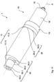
- eine Explosionsdarstellung eines Teils der Bestandteile des erfindungsgemässen Drucksensors 1 gemäss der
Fig. 1 bis 6 , mit der Sensoreinheit 10, dem Gehäuse 20, der Hülse 30 und dem Dichtelement 40; - Fig. 9
- eine Ansicht eines ersten Schrittes des erfindungsgemässen Verfahrens der Fertigung des erfindungsgemässen Drucksensors 1 gemäss der
Fig. 1 bis 6 , wo das Gehäuse 20 auf die Sensoreinheit 10 gesetzt wird; - Fig. 10
- eine Ansicht eines zweiten Schrittes des erfindungsgemässen Verfahrens der Fertigung des erfindungsgemässen Drucksensors 1 gemäss
Fig. 9 , wo das Dichtelement 40 auf das Gehäuse 20 gesetzt wird; und - Fig. 11
- eine Ansicht eines dritten Schrittes des erfindungsgemässen Verfahrens der Fertigung des erfindungsgemässen Drucksensors 1 gemäss
Fig. 10 , wo die Hülse 30 auf das Dichtelement 40 und das Gehäuse 20 gesetzt wird. - Gleiche Bezugszeichen bezeichnen in den Figuren gleiche Gegenstände.
- Die
Fig. 1 bis 6 zeigen Querschnitte durch mehrere Ausführungsformen eines Teiles eines erfindungsgemässen Drucksensors 1. Der Drucksensor 1 hat die Funktion, den Druck P eines Mediums M in einem Druckraum C zu messen. Der Druckraum C kann sich in einem Spritzgiesswerkzeug, in einem Verbrennungsmotor, usw. befinden. Bei einem Spritzgiesswerkzeug ist das Medium M eine flüssige Schmelze aus Kunststoff, Metall, usw. Bei einem Verbrennungsmotor ist das Medium M ein Kraftstoff-Luft-Gemisch. Das Medium M kann eine Temperatur T von mehreren hundert °C und einen Druck P von mehreren tausend bar haben. Vorzugsweise liegt die Temperatur T im Bereich von 100 °C bis 500 °C und der Druck P liegt im Bereich von 50 bar bis 5000 bar. Der zu messende Druck P ist in denFig. 1 bis 6 schematisch als schwarze Pfeile dargestellt. - Der Drucksensor 1 weist eine Sensoreinheit 10 auf. Die Sensoreinheit 10 hat die Funktion, ein Messelement 12 zu beherbergen. Die Sensoreinheit 10 ist in den
Fig. 1 bis 6 nur teilweise dargestellt, dafür ist die Sensoreinheit 10 im Querschnitt derFig. 7 und in der Explosionsdarstellung derFig. 8 vollständig dargestellt. - Der Drucksensor 1 weist eine Längsachse A auf. Die
Fig. 1 bis 8 zeigen den Drucksensor 1 entlang der Längsachse A. - Der Drucksensor 1 weist ein Gehäuse 20 auf. Das Gehäuse 20 hat die Funktion, die Sensoreinheit 10 in einer Bohrung H einer Wandung W des Druckraumes C zu befestigen. Die Befestigung des Drucksensors 1 über das Gehäuse 20 in der Bohrung H kann eine Schraubverbindung sein. Die Schraubverbindung ist figürlich nicht dargestellt.
- In den figürlich dargestellten Ausführungsformen ist das Gehäuse 20 hohlzylinderförmig und besteht aus mechanisch beständigem Material wie aus Reinmetallen, Nickellegierungen, Kobaltlegierungen, Eisenlegierungen, usw. Wie gut in
Fig. 8 zu erkennen ist, weist das Gehäuse 20 ein distales Gehäuseende 20.1 und ein proximales Gehäuseende 20.2 auf, welches distale Gehäuseende 20.1 auf der Längsachse A weiter entfernt als das proximale Gehäuseende 20.2 vom Messelement 12 angeordnet ist. Das Gehäuse 20 weist einen Gehäuseinnenraum 20.3 auf. Bezüglich der Längsachse A umschliesst das Gehäuse 20 den Gehäuseinnenraum 20.3 radial. Im Gehäuseinnenraum 20.3 ist die Sensoreinheit 10 angeordnet. - Zusätzlich zum Messelement 12 weist die Sensoreinheit 10 eine Stempeleinheit 11 auf.
- Die Stempeleinheit 11 hat die erste Funktion, den zu messenden Druck P aufzunehmen und auf das Messelement 12 zu übertragen. Dazu weist die Stempeleinheit 11 ein distales Stempelende 11.1, ein proximales Stempelende 11.2 und eine Vorspannhülse 11.3 auf. Die Stempeleinheit 11 besteht aus mechanisch beständigem Material wie aus Reinmetallen, Nickellegierungen, Kobaltlegierungen, Eisenlegierungen, usw. In den figürlich dargestellten Ausführungsformen sind das distale Stempelende 11.1, das proximale Stempelende 11.2 und die Vorspannhülse 11.3 einstückig. Dabei sind das distale Stempelende 11.1 und das proximale Stempelende 11.2 zylinderförmig und gehen ineinander über. Das proximale Stempelende 11.2 geht in die Vorspannhülse 11.3 über. Die Vorspannhülse 11.3 ist hohlzylinderförmig und umschliesst einen Vorspannhülsenraum 11.4. Im Vorspannhülsenraum 11.4 ist das Messelement 12 angeordnet. Das distale Stempelende 11.1 ist auf der Längsachse A weiter entfernt als das proximale Stempelende 11.2 vom Messelement 12 angeordnet. Das distale Stempelende 11.1 weist an seinem Ende eine Stirnfläche auf, welche auch Druckaufnahmefläche 11.11 genannt wird. Der zu messende Druck P wirkt über die Druckaufnahmefläche 11.11 auf das distale Stempelende 11.1 und wird vom distalen Stempelende 11.1 auf das proximale Stempelende 11.2 übertragen. Vom proximalen Stempelende 11.2 wirkt der zu messende Druck P dann direkt auf das Messelement 12.
- Die Stempeleinheit 11 hat die weitere Funktion zu verhindern, dass mechanische Verspannungen, welche von der Befestigung des Drucksensors 1 in der Bohrung H der Wandung W des Druckraumes C stammen, nicht vom Gehäuse 20 zum Messelement 12 gelangen, denn solche mechanische Verspannungen können die Messung des Druckes P verfälschen. Dazu weist die Stempeleinheit 11 einen Vorspannkörper 11.5 auf. In der figürlich dargestellten Ausführungsform ist der Vorspannkörper 11.5 hohlzylinderförmig. Ein vom proximalen Stempelende 11.2 abgewandtes Ende der Vorspannhülse 11.3 ist am Vorspannkörper 11.5 befestigt. Durch die Befestigung ist das Messelement 12 auf der Längsachse A zwischen dem proximalen Stempelende 11.2 und dem Vorspannkörper 11.5 unter mechanischer Vorspannung angeordnet. Der Ausdruck "mechanische Vorspannung" besagt, dass die mechanische Vorspannung vor der eigentlichen Messung des Druckes P gebildet wird. Vorzugsweise ist ein Betrag der mechanischen Vorspannung um mindestens eine dezimale Grössenordnung grösser als mögliche mechanische Verspannungen von der Befestigung des Drucksensors 1 über das Gehäuse 20 in der Wandung W des Druckraumes C.
- Die Vorspannhülse 11.3 ist dünnwandig mit einer Wandstärke von kleiner/gleich 0.1 mm. Die dünnwandige Vorspannhülse 11.3 ermöglicht eine grosse Beweglichkeit des Stempels 11 und somit eine hohe Empfindlichkeit des Drucksensors 1. Ein Eindringen von Medium M mit hoher Temperatur T und hohem Druck P durch den Spalt 30.4 in den Gehäuseinnenraum 20.3 gilt es zu verhindern. Bei einem Spritzgiesswerkzeug ist das Medium M eine flüssige Schmelze, welche flüssige Schmelze im Gehäuseinnenraum 20.3 aushärten und so die Beweglichkeit des Stempels 11 verhindern würde. Bei einem Verbrennungsmotor ist das Medium M ein Kraftstoff-Luft-Gemisch, welches Kraftstoff-Luft-Gemisch chemisch aggressiv ist und im Gehäuseinnenraum 20.3 die Vorspannhülse 11.3 korrodieren und somit beschädigen oder zerstören würde.
- Das Messelement 12 hat die Funktion für den zu messenden Druck P ein Messsignal S zu erzeugen. Das Messelement 12 kann ein piezoelektrisches Messelement, ein piezoresistives Messelement, ein Dehnungsmessstreifen, usw. sein. Eine Grösse des Messsignals S ist proportional zum gemessenen Druck P.
- Die Sensoreinheit 10 weist auch eine Elektrodenanordnung 13, eine Buchseneinheit 14, einen Buchsenkontakt 15 und einen Isolationskörper 16 auf.
- Die Buchseneinheit 14 hat die Funktion, die Elektrodenanordnung 13, den Buchsenkontakt 15 und den Isolationskörper 16 zu beherbergen. Dazu weist die Buchseneinheit 14 ein hohlzylinderförmiges Buchsengehäuse aus mechanisch beständigem Material wie aus Reinmetallen, Nickellegierungen, Kobaltlegierungen, Eisenlegierungen, usw. auf. Das Buchsengehäuse ist über eine Buchsengehäuse-Vorspannkörper-Verbindung auf der vom Messelement 12 abgewandten Seite des Vorspannkörpers 11.5 am Vorspannkörper 11.5 befestigt. Im Inneren des Buchsengehäuses weist die Buchseneinheit 14 einen Buchsenraum auf. Im Buchsenraum sind die Elektrodenanordnung 13, der Buchsenkontakt 15 und der Isolationskörper 16 angeordnet.
- Die Elektrodenanordnung 13 hat die Funktion, das Messsignal S vom Messelement 12 zum Buchsenkontakt 15 abzuleiten. In der figürlich dargestellten Ausführungsform der Sensoreinheit 10 ist die Elektrodenanordnung 13 zylinderförmig und besteht aus elektrisch leitfähigem Material wie aus Kupfer, Silber, Gold, usw. Die Elektrodenanordnung 13 ist am dem Messelement 12 zugewandten Ende der Buchseneinheit 14 angeordnet und erstreckt sich aus dem Buchsenraum in den Vorspannhülsenraum 11.4. Die Elektrodenanordnung 13 ist elektrisch mit dem Messelement 12 verbunden. Die Elektrodenanordnung 1 leitet das Messsignal S vom Messelement 12 entlang der Längsachse A zum Buchsenkontakt 15 ab.
- Der Buchsenkontakt 15 hat die Funktion, das Messsignal S ausserhalb des Buchseneinheit 14 zur Verfügung zu stellen. In der figürlich dargestellten Ausführungsform ist der Buchsenkontakt 15 zylinderförmig und besteht aus elektrisch leitfähigem Material wie aus Kupfer, Silber, Gold, usw. Der Buchsenkontakt 15 ist am vom Messelement 12 abgewandten Ende der Buchseneinheit 14 angeordnet. Die Elektrodenanordnung 13 und der Buchsenkontakt 15 sind elektrisch miteinander verbunden.
- Der Isolationskörper 16 hat die Funktion, die Elektrodenanordnung 13 und den Buchsenkontakt 15 elektrisch gegenüber dem Buchsengehäuse zu isolieren. Der Isolationskörper 16 ist hohlzylinderförmig und besteht aus elektrisch isolierendem und mechanisch steifem Material wie Keramik, Al2O3-Keramik, Saphir, usw. Bezüglich der Längsachse A ist der Isolationskörper 16 radial ausserhalb der Elektrodenanordnung 13 und des Buchsenkontaktes 15 angeordnet.
- Somit sind die Stempeleinheit 11 und das Messelement 12 als Bestandteil der Sensoreinheit 10 im Gehäuseinnenraum 20.3 angeordnet. Das distale Stempelende 11.1 ragt aus dem Gehäuse 20. Gemäss
Fig. 1 weist das distale Gehäuseende 20.1 eine Gehäuseöffnung 20.4 auf. Das distale Stempelende 11.1 ragt durch die Gehäuseöffnung 20.4 bis zum Druckraum C. - Erfindungsgemäss weist der Drucksensor 1 eine Hülse 30 auf. Die Hülse 30 hat die Funktion, mindestens ein Dichtelement 40 zu beherbergen. Die Hülse 30 ist hohlzylinderförmig und besteht aus mechanisch beständigem Material wie aus Reinmetallen, Nickellegierungen, Kobaltlegierungen, Eisenlegierungen, usw. In den figürlich dargestellten Ausführungsformen weist die Hülse 30 ein distales Hülsenende 30.1 und ein proximales Hülsenende 30.2 auf, welches distale Hülsenende 30.1 entlang der Längsachse A weiter entfernt als das proximale Hülsenende 30.2 vom Messelement 12 angeordnet ist.
- Vorzugsweise ragt das distale Stempelende 11.1 bis zum distalen Hülsenende 30.1. Die Druckaufnahmefläche 11.11 und das distale Hülsenende 30.1 liegen in einer Druckaufnahmeebene B senkrecht zur Längsachse A. Dies hat den einen Vorteil, dass der Druck P nur parallel zur Längsachse A über die Druckaufnahmefläche 11.11 auf das distale Stempelende 11.1 wirken kann. Somit wird verhindert, dass eine nicht-parallel zur Längsachse A wirkende Druckkomponente auf das distale Stempelende 11.1 wirkt, was die Messung des Druckes P verfälschen kann, wenn das Messelement 12 für solch eine nicht-parallel zur Längsachse A wirkende Druckkomponente Störsignale erzeugt. Die Vermeidung einer solchen nicht-parallel zur Längsachse A wirkenden Druckkomponente erhöht die Empfindlichkeit und Genauigkeit der Messung des Druckes P. Alternativ hat dies den Vorteil, dass sich das distale Stempelende 11.1 und das distale Hülsenende 30.1 durch Ablängen gezielt auf die Oberflächengeometrie der Wandung W des Druckraumes C anpassen lassen. Das distale Stempelende 11.1 und das distale Hülsenende 30.1 lassen sich somit auf eine schräg oder gekrümmt zur Längsachse A verlaufende Oberflächengeometrie der Wandung W des Druckraumes C ablängen.
- Die Hülse 30 ist am Gehäuse 20 befestigt. Vorzugsweise ist die Hülse 30 am proximalen Hülsenende 30.2 über eine Hülse-Gehäuse-Verbindung 30.3 am distalen Gehäuseende 20.1 befestigt. Bezüglich der Längsachse A ist die Hülse-Gehäuse-Verbindung 30.3 radial aussenseitig am proximalen Hülsenende 30.2 und am distalen Gehäuseende 20.1 angeordnet. Die Hülse-Gehäuse-Verbindung 30.3 erfolgt durch Schweissen, Löten, Verschrauben, Verpressen, Verkleben, usw. In den figürlich dargestellten Ausführungsformen ist die Hülse-Gehäuse-Verbindung 30.3 eine Schweissverbindung.
- Die Hülse 30 umschliesst das distale Stempelende 11.1 bereichsweise. Bezüglich der Längsachse A umschliesst die Hülse 30 das distale Stempelende 11.1 radial aussenseitig. Das distale Stempelende 11.1 weist eine Mantelfläche auf. Vorzugsweise umschliesst die Hülse 30 die Mantelfläche des distalen Stempelendes 11.1 radial aussenseitig in einem Winkel von 360°.
- Die Hülse 30 und das distale Stempelende 11.1 sind durch einen Spalt 30.4 voneinander beabstandet. Vorzugsweise weist der Spalt 30.4 in radialer Richtung senkrecht zur Längsachse A eine Breite von kleiner/gleich 0.1 mm auf.
- Die Hülse 30 und Gehäuse 20 bilden mindestens eine Nut 50. Die Nut 50 dient der Beherbergung des Dichtelementes 40. Vorzugsweise ist die Nut 50 im Bereich des proximalen Hülsenendes 30.2 und des distalen Gehäuseendes 20.1 angeordnet. Das Dichtelement 40 ist in der Nut 50 angeordnet.
- Entlang der Längsachse A kann die Hülse 30 eine Länge von mehreren cm aufweisen. Die Nut 50 und das Dichtelement 40 befinden sich dann in einer relativ grossen Entfernung von mehreren cm zum Druckraum C. Dies hat den Vorteil, dass bei einem Medium M mit hoher Temperatur T das Dichtelement 40 im Betrieb des Drucksensors 1 nicht der hohen Temperatur T des Mediums M ausgesetzt ist, da die Temperatur T in der Wandung W und somit auch in der Hülse 30 mit steigender Entfernung zum Druckraum C abnimmt.
- Entlang der Längsachse A s kann die Hülse 30 aber auch eine Länge von nur einigen mm aufweisen. Die Nut 50 und das Dichtelement 40 befinden sich dann in einer relativ geringen Entfernung von einigen mm zum Druckraum C. Dies hat den Vorteil, dass ein Medium M mit niedriger Viskosität entlang der Längsachse A nicht weit in den Spalt 30.4 eindringen kann, bevor es auf das Dichtelement 40 stösst.
- Die Nut 50 ist bezüglich der Längsachse A radial innenseitig an der Hülse 30 und am Gehäuse 20 angeordnet. Die Nut 50 ist ringförmig. Die Nut 50 weist mehrere Nutenwände 50.1, 50.2, 50.3 auf. Mindestens eine der Nutenwände 50.1, 50.2, 50.3 ist Teil des proximalen Hülsenendes 30.2. Mindestens eine der Nutenwände 50.1, 50.2, 50.3 ist Teil des distalen Gehäuseendes 20.1.
- In der Ausführungsform des Drucksensors 1 gemäss
Fig. 1 ist die Nut 50 im Querschnitt rechteckig und weist drei Nutenwände 50.1, 50.2, 50.3 auf. Von den drei Nutenwänden 50.1, 50.2, 50.3 sind eine erste Nutenwand 50.1 und eine zweite Nutenwand 50.2 Teil des proximalen Hülsenendes 30.2 und eine dritte Nutenwand 50.3 ist Teil des distalen Gehäuseendes 20.1. Die erste Nutenwand 50.1 und die dritte Nutenwand 50.3 sind gerade und in einem Winkel von 90° zur Längsachse A angeordnet, die zweite Nutenwand 50.2 ist gerade und parallel zur Längsachse A angeordnet. - In der Ausführungsform des Drucksensors 1 gemäss
Fig. 2 ist die Nut 50 im Querschnitt dreieckig und weist zwei Nutenwände 50.1, 50.2 auf. Von den zwei Nutenwänden 50.1, 50.2 ist eine erste Nutenwand 50.1 Teil des proximalen Hülsenendes 30.2 und eine zweite Nutenwand 50.2 ist Teil des distalen Gehäuseendes 20.1. Die erste Nutenwand 50.1 und die zweite Nutenwand 50.2 sind schräg zur Längsachse A angeordnet. Vorzugsweise sind die erste Nutenwand 50.1 und die zweite Nutenwand 50.2 in einem Winkel von 30° zur Längsachse A angeordnet. Die zwei schrägen Nutenwände 50.1, 50.2 erlauben eine genaue Positionierung des Dichtelementes 40 in der Nut 50. - In der Ausführungsform des Drucksensors 1 gemäss
Fig. 3 ist die Nut 50 im Querschnitt trapezförmig und weist drei Nutenwände 50.1, 50.2, 50.3 auf. Von den drei Nutenwänden 50.1, 50.2, 50.3 sind eine erste Nutenwand 50.1 und eine zweite Nutenwand 50.2 Teil des proximalen Hülsenendes 30.2 und eine dritte Nutenwand 50.3 ist Teil des distalen Gehäuseendes 20.1. Die erste Nutenwand 50.1 und die dritte Nutenwand 50.3 sind schräg zur Längsachse A angeordnet, die zweite Nutenwand 50.2 ist gerade und parallel zur Längsachse A angeordnet. Vorzugsweise sind die erste Nutenwand 50.1 und die dritte Nutenwand 50.3 in einem Winkel von 30° zur Längsachse A angeordnet. - In der Ausführungsform des Drucksensors 1 gemäss
Fig. 4 ist die Nut im Querschnitt rund und weist zwei Nutenwände 50.1, 50.2 auf. Von den zwei Nutenwänden 50.1, 50.2 ist eine erste Nutenwand 50.1 Teil des proximalen Hülsenendes 30.2 und eine zweite Nutenwand 50.2 ist Teil des distalen Gehäuseendes 20.1. Die erste Nutenwand 50.1 ist rund und von der Längsachse A in das proximale Hülsenende 30.2 gewölbt. Vorzugsweise weist die Wölbung einen konstanten Radius auf. Die zweite Nutenwand 50.2 ist rund und von der Längsachse A in das distale Gehäuseende 20.1 gewölbt. Vorzugsweise weist die Wölbung einen konstanten Radius auf. Die zwei runden Nutenwände 50.1, 50.2 erlauben eine genaue Positionierung des Dichtelementes 40 in der Nut 50. - In der Ausführungsform des Drucksensors 1 gemäss
Fig. 5 ist die Nut halbrund und weist drei Nutenwände 50.1, 50.2, 50.3 auf. Von den drei Nutenwänden 50.1, 50.2, 50.3 sind eine erste Nutenwand 50.1 und eine zweite Nutenwand 50.2 Teil des proximalen Hülsenendes 30.2 und eine dritte Nutenwand 50.3 ist Teil des distalen Gehäuseendes 20.1. Die erste Nutenwand 50.1 ist rund und von der Längsachse A in das proximale Hülsenende 30.2 gewölbt. Vorzugsweise weist die Wölbung einen konstanten Radius auf. Die zweite Nutenwand 50.2 ist gerade und parallel zur Längsachse A angeordnet. Die dritte Nutenwand 50.3 ist gerade und in einem Winkel von 90° zur Längsachse A angeordnet. - In der Ausführungsform des Drucksensors 1 gemäss
Fig. 6 ist die Nut halbrund und weist drei Nutenwände 50.1, 50.2, 50.3 auf. Von den drei Nutenwänden 50.1, 50.2, 50.3 sind eine erste Nutenwand 50.1 und eine zweite Nutenwand 50.2 Teil des proximalen Hülsenendes 30.2 und eine dritte Nutenwand 50.3 ist Teil des distalen Gehäuseendes 20.1. Die erste Nutenwand 50.1 ist gerade und in einem Winkel von 90° zur Längsachse A angeordnet. Die zweite Nutenwand 50.2 ist gerade und parallel zur Längsachse A angeordnet. Die dritte Nutenwand 50.3 ist rund und von der Längsachse A in das distale Gehäuseende 20.1 gewölbt. Vorzugsweise weist die Wölbung einen konstanten Radius auf. - Bei Kenntnis der vorliegenden Erfindung kann der Fachmann die in den
Fig. 1 bis 6 dargestellten sechs Ausführungsformen der Nut auch miteinander kombinieren. - Erfindungsgemäss weist der Drucksensor 1 mindestens ein Dichtelement 40 auf. Das Dichtelement 40 hat die Funktion, den Spalt 30.4 abzudichten. Im Sinne der Erfindung hat das Verb "abdichten" die Bedeutung, dass im Betrieb des Drucksensors 1 kein Medium M durch den Spalt 30.4 in den Gehäuseinnenraum 20.3 gelangen kann. Vorzugsweise dichtet das Dichtelement 40 den Spalt 30.4 dauerhaft bei einer Temperatur im Bereich von 100 °C bis 500 °C sowie bei einem Druck P im Bereich von 50 bar bis 5000 bar ab. Das Dichtelement 40 ist torusförmig und besteht aus elastisch dichtendem Material wie aus Elastomer, insbesondere aus Fluorelastomer oder aus Perfluorelastomer, aus Kautschuk, insbesondere aus Acrylnitril-Butadien-Kautschuk, usw.
- In den figürlich dargestellten Ausführungsformen weist das Dichtelement 40 einen torusförmigen Dichtkörper 40.1 und eine Torusöffnung 40.2 auf. Der torusförmige Dichtkörper 40.1 umschliesst die Torusöffnung 40.2. Das distale Stempelende 11.1 ragt durch die Torusöffnung 40.2.
- Das Dichtelement 40 ist in der Nut 50 angeordnet. Das Dichtelement 40 dichtet den Spalt 30.4 durch Dichtpressung. Die Dichtpressung kann als axiale Dichtpressung entlang der Längsachse A, oder als radiale Dichtpressung senkrecht zur Längsachse A, oder als eine Kombination aus axialer Dichtpressung entlang der Längsachse A und radialer Dichtpressung senkrecht zur Längsachse A erfolgen. Das Dichtelement 40 ist mit einer Vorpressung in der Nut 50 angeordnet. Die Vorpressung wird von den Nutenwände 50.1, 50.2, 50.3 auf das Dichtelement 40 ausgeübt. Zusätzlich zu Vorpressung wirkt der Druck P im Spalt 30.4 als Druckpressung auf das Dichtelement 40. Die Dichtpressung wird somit von der Vorpressung und der Druckpressung gebildet.
- Bei Kenntnis der vorliegenden Erfindung kann der Fachmann auch mehrere Dichtelemente in einer Nut oder in mehreren Nuten anordnen. Bezüglich der Längsachse A sind die Mehrzahl der Dichtelemente dann hintereinander angeordnet und dichten den Spalt 30.4 dann mehrmals ab.
- Die
Fig. 9 bis 11 zeigen in Ansichten drei Schritte des erfindungsgemässen Verfahrens zur Fertigung des Drucksensors 1. Auch die Ansichten derFig. 9 bis 11 zeigen den Drucksensor 1 entlang einer Längsachse A des Drucksensors 1. - In einem ersten Schritt des erfindungsgemässen Verfahrens gemäss
Fig. 9 werden ein Gehäuse 20 und eine Sensoreinheit 10 bereitgestellt und das Gehäuse 20 wird entlang der Längsachse A über die Stempeleinheit 11 geschoben und auf die Sensoreinheit 10 gesetzt. Dadurch gerät die Stempeleinheit 11 in den Gehäuseinnenraum 20.3. Das distale Stempelende 11.1 ragt dadurch durch die Gehäuseöffnung 20.4. Das proximale Gehäuseende 20.2 sitzt auf dem Vorspannkörper 11.5. Das so auf den Vorspannkörper 11.5 gesetzte Gehäuse 20 wird über eine Gehäuse-Vorspannkörper-Verbindung 20.5 am Vorspannkörper 11.5 befestigt. Bezüglich der Längsachse A ist die Gehäuse-Vorspannkörper-Verbindung 20.5 radial aussenseitig am Gehäuse 20 und am Vorspannkörper 11.5 angeordnet. Die Gehäuse-Vorspannkörper-Verbindung 20.5 erfolgt durch Schweissen, Löten, Verschrauben, usw. In den figürlich dargestellten Ausführungsformen ist die Gehäuse-Vorspannkörper-Verbindung 20.5 eine Schweissverbindung. - In einem zweiten Schritt des erfindungsgemässen Verfahrens gemäss
Fig. 10 wird ein Dichtelement 40 bereitgestellt und entlang der Längsachse A über das distale Stempelende 11.1 geschoben und auf das Gehäuse 20 gesetzt. Das distale Stempelende 11.1 ragt dadurch durch die Torusöffnung 40.2. - In einem dritten Schritt des erfindungsgemässen Verfahrens gemäss
Fig. 11 wird eine Hülse 30 bereitgestellt und entlang der Längsachse A über das distale Stempelende 11.1 geschoben und auf das Dichtelement 40 und das Gehäuse 20 gesetzt. Das proximale Hülsenende 30.2 sitzt auf dem distalen Gehäuseende 20.1. Die so auf das Gehäuse 20 gesetzte Hülse 30 wird über die Hülse-Gehäuse-Verbindung 30.3 am Gehäuse 20 befestigt. Das Dichtelement 40 wird durch die aufgesetzte Hülse 30 und das Gehäuse 20 vorgepresst. -
- 1
- Drucksensor
- 11
- Stempeleinheit
- 11.1
- distales Stempelende
- 11.11
- Druckaufnahmefläche
- 11.2
- proximales Stempelende
- 11.3
- Vorspannhülse
- 11.4
- Vorspannhülsenraum
- 11.5
- Vorspannkörper
- 12
- Messelement
- 14
- Buchseneinheit
- 10
- Sensoreinheit
- 13
- Elektrodenanordnung
- 15
- Buchsenkontakt
- 16
- Isolationskörper
- 20
- Gehäuse
- 20.1
- distales Gehäuseende
- 20.2
- proximales Gehäuseende
- 20.3
- Gehäuseinnenraum
- 20.4
- Gehäuseöffnung
- 20.5
- Gehäuse-Vorspannkörper-Verbindung
- 30
- Hülse
- 30.1
- distales Hülsenende
- 30.2
- proximales Hülsenende
- 30.3
- Hülse-Gehäuse-Verbindung
- 30.4
- Spalt
- 40
- Dichtelement
- 40.1
- torusförmiger Dichtkörper
- 40.2
- Torusöffnung
- 50
- Nut
- 50.1
- erste Nutenwand
- 50.2
- zweite Nutenwand
- 50.3
- dritte Nutenwand
- A
- Längsachse
- B
- Druckaufnahmeebene
- C
- Druckraum
- H
- Bohrung
- M
- Medium
- P
- Druck
- S
- Messsignal
- T
- Temperatur
- W
- Wandung
Claims (15)
- Drucksensor (1) mit einem Gehäuse (20), einer Stempeleinheit (11) und einem Messelement (12); welches Gehäuse (20) einen Gehäuseinnenraum (20.3) aufweist und welche Stempeleinheit (11) und welches Messelement (12) im Gehäuseinnenraum (20.3) angeordnet sind; welche Stempeleinheit (11) ein distales Stempelende (11.1) und ein proximales Stempelende (11.2) aufweist, welches distale Stempelende (11.1) auf einer Längsachse (A) des Drucksensors (1) weiter entfernt als das proximale Stempelende (11.2) vom Messelement (12) angeordnet ist und welches distale Stempelende (11.1) aus dem Gehäuse (20) ragt und welches proximale Stempelende (11.2) mit dem Messelement (12) in Wirkverbindung steht und einen ausserhalb des Gehäuses (20) herrschender Druck (P) eines Mediums (M) auf das Messelement (12) überträgt; dadurch gekennzeichnet,dass der Drucksensor (1) eine Hülse (30) aufweist, welche Hülse (30) am Gehäuse (20) befestigt ist;dass die Hülse (30) und das distale Stempelende (11.1) durch einen Spalt (30.4) voneinander beabstandet sind; und dass der Drucksensor (1) mindestens ein Dichtelement (40) aufweist, welches Dichtelement (40) den Spalt (30.4) für das Medium (M) zum Gehäuseinnenraum (20.3) per Dichtpressung abdichtet.
- Drucksensor (1) nach Anspruch 1, dadurch gekennzeichnet, dass das Dichtelement (40) torusförmig ist und aus elastisch dichtendem Material wie Elastomer, insbesondere aus Fluorelastomer oder aus Perfluorelastomer, oder aus Kautschuk, insbesondere aus Acrylnitril-Butadien-Kautschuk besteht.
- Drucksensor (1) nach Anspruch 2, dadurch gekennzeichnet, dass das Dichtelement (40) einen torusförmigen Dichtkörper (40.1) und eine Torusöffnung (40.2) aufweist, welcher torusförmige Dichtkörper (40.1) die Torusöffnung (40.2) umschliesst; und dass das distale Stempelende (11.1) durch die Torusöffnung (40.2) ragt.
- Drucksensor (1) nach einem der Ansprüche 1 bis 3, dadurch gekennzeichnet, dass die Hülse (30) und Gehäuse (20) bezüglich der Längsachse (A) radial innenseitig eine Nut (50) bilden; und dass das Dichtelement (40) in der Nut (50) angeordnet ist.
- Drucksensor (1) nach Anspruch 4, dadurch gekennzeichnet, dass die Nut (50) mehrere Nutenwände (50.1, 50.2, 50.3) aufweist; dass die Nutenwände (50.1, 50.2, 50.3) eine Vorpressung auf das in der Nut (50) angeordnete Dichtelement (40) ausüben; und dass der Druck (P) im Spalt (30.4) zusätzlich zur Vorpressung als Druckpressung auf das Dichtelement (40) wirkt, welche Vorpressung und welche Druckpressung die Dichtpressung bilden.
- Drucksensor (1) nach Anspruch 4, dadurch gekennzeichnet, dass das Gehäuse (20) ein distales Gehäuseende (20.1) und ein proximales Gehäuseende (20.2) aufweist, welches distale Gehäuseende (20.1) entlang der Längsachse (A) weiter entfernt als das proximale Gehäuseende (20.2) vom Messelement (12) angeordnet ist; dass die Hülse (30) ein distales Hülsenende (30.1) und ein proximales Hülsenende (30.2) aufweist, welches distale Hülsenende (30.1) entlang der Längsachse (A) weiter entfernt als das proximale Hülsenende (30.2) vom Messelement (12) angeordnet ist; und dass die Nut (50) im Bereich des distalen Gehäuseendes (20.1) und des proximales Hülsenendes (30.2) angeordnet ist.
- Drucksensor (1) nach Anspruch 6, dadurch gekennzeichnet, dass die Nut (50) mehrere Nutenwände (50.1, 50.2, 50.3) aufweist, von denen mindestens eine Nutenwand (50.1, 50.2) Teil des proximalen Hülsenendes (30.2) ist und von denen mindestens eine Nutenwand (50.2, 50.3) Teil des distalen Gehäuseendes (20.1) ist.
- Drucksensor (1) nach Anspruch 7, dadurch gekennzeichnet, dass die Nut (50) im Querschnitt rechteckig oder dreieckig oder trapezförmig oder rund oder halbrund ist.
- Drucksensor (1) nach einem der Ansprüche 1 bis 8, dadurch gekennzeichnet, dass die Stempeleinheit (11) eine Vorspannhülse (11.3) und einen Vorspannkörper (11.5) aufweist; dass das proximale Stempelende (11.2) in die Vorspannhülse (11.3) übergeht; dass die Vorspannhülse (11.3) einen Vorspannhülsenraum (11.4) umschliesst, in welchem Vorspannhülsenraum (11.4) das Messelement (12) angeordnet ist; dass ein vom proximalen Stempelende (11.2) abgewandtes Ende der Vorspannhülse (11.3) am Vorspannkörper (11.5) befestigt ist; und dass das Messelement (12) auf der Längsachse (A) zwischen dem proximalen Stempelende (11.2) und dem Vorspannkörper (11.5) unter mechanischer Vorspannung angeordnet ist.
- Drucksensor (1) nach einem der Ansprüche 1 bis 9, dadurch gekennzeichnet, dass der Drucksensor (1) über das Gehäuse (20) in einer Bohrung (H) einer Wandung (W) eines Druckraumes (C) befestigbar ist; dass der Druckraum (C) in einem Spritzgiesswerkzeug oder in einem Verbrennungsmotor angeordnet ist; und dass der Druck (P) im Bereich von 50 bar bis 5000 bar liegt.
- Verfahren zur Fertigung eines Drucksensors (1), mit einem Gehäuse (20), einer Stempeleinheit (11) und einem Messelement (12); welches Gehäuse (20) einen Gehäuseinnenraum (20.3) aufweist und welche Stempeleinheit (11) und welches Messelement (12) im Gehäuseinnenraum (20.3) angeordnet sind; welche Stempeleinheit (11) ein distales Stempelende (11.1) und ein proximales Stempelende (11.2) aufweist, welches distale Stempelende (11.1) auf einer Längsachse (A) des Drucksensors (1) weiter entfernt als das proximale Stempelende (11.2) vom Messelement (12) angeordnet ist und welches distale Stempelende (11.1) aus dem Gehäuse (20) ragt und welches proximale Stempelende (11.2) mit dem Messelement (12) in Wirkverbindung steht und einen ausserhalb des Gehäuses (20) herrschender Druck (P) eines Mediums (M) auf das Messelement (12) überträgt;
dadurch gekennzeichnet,dass in einem ersten Schritt des Verfahrens das Gehäuse (20) und eine Sensoreinheit (10) mit einer Stempeleinheit (11) und einem Messelement (12) bereitgestellt werden, und dass das Gehäuse (20) entlang der Längsachse (A) über die Stempeleinheit (11) geschoben und auf die Sensoreinheit (10) gesetzt wird;dass in einem zweiten Schritt des Verfahrens mindestens ein Dichtelement (40) bereitgestellt wird, und dass das Dichtelement (40) entlang der Längsachse (A) über das distale Stempelende (11.1) geschoben und auf das Gehäuse (20) gesetzt wird; unddass in einem dritten Schritt des Verfahrens eine Hülse (30) bereitgestellt wird und entlang der Längsachse (A) über das distale Stempelende (11.1) geschoben und auf das Dichtelement (40) und das Gehäuse (20) gesetzt wird, welche Hülse (30) und welches distale Stempelende (11.1) durch einen Spalt (30.4) voneinander beabstandet sind, und welches Dichtelement (40) den Spalt (30.4) für das Medium (M) zum Gehäuseinnenraum (20.3) per Dichtpressung abdichtet. - Verfahren nach Anspruch 11, dadurch gekennzeichnet, dass im ersten Schritt des Verfahrens das auf den Vorspannkörper (11.5) gesetzte Gehäuse (20) über eine Gehäuse-Vorspannkörper-Verbindung (20.5) am Vorspannkörper (11.5) befestigt wird; welche Gehäuse-Vorspannkörper-Verbindung (20.5) bezüglich der Längsachse (A) radial aussenseitig am Gehäuse (20) und am Vorspannkörper (11.5) angeordnet ist.
- Verfahren nach einem der Ansprüche 11 oder 12, dadurch gekennzeichnet, dass im dritten Schritt des Verfahrens durch das Aufsetzen der Hülse (30) auf das Gehäuse (20) um das Dichtelement (40) bezüglich der Längsachse (A) radial innenseitig an der Hülse (30) und am Gehäuse (20) eine Nut (50) gebildet wird.
- Verfahren nach einem der Ansprüche 11 bis 13, dadurch gekennzeichnet, dass im dritten Schritt des Verfahrens das Dichtelement (40) durch die aufgesetzte Hülse (30) und das Gehäuse (20) vorgepresst wird.
- Verfahren nach einem der Ansprüche 11 bis 14, dadurch gekennzeichnet, dass im dritten Schritt des Verfahrens die auf das Gehäuse (20) gesetzte Hülse (30) über eine Hülse-Gehäuse-Verbindung (30.3) am Gehäuse (20) befestigt wird, welche Hülse-Gehäuse-Verbindung (30.3) bezüglich der Längsachse (A) radial aussenseitig an der Hülse (30) und am Gehäuse (20) angeordnet ist.
Applications Claiming Priority (1)
| Application Number | Priority Date | Filing Date | Title |
|---|---|---|---|
| EP23210128 | 2023-11-15 |
Publications (1)
| Publication Number | Publication Date |
|---|---|
| EP4556872A1 true EP4556872A1 (de) | 2025-05-21 |
Family
ID=88837084
Family Applications (1)
| Application Number | Title | Priority Date | Filing Date |
|---|---|---|---|
| EP24182378.0A Pending EP4556872A1 (de) | 2023-11-15 | 2024-06-14 | Drucksensor und verfahren zu dessen fertigung |
Country Status (5)
| Country | Link |
|---|---|
| US (1) | US20250155303A1 (de) |
| EP (1) | EP4556872A1 (de) |
| JP (1) | JP2025081208A (de) |
| KR (1) | KR20250071816A (de) |
| CN (1) | CN120008802A (de) |
Citations (4)
| Publication number | Priority date | Publication date | Assignee | Title |
|---|---|---|---|---|
| WO2006032152A1 (de) | 2004-09-22 | 2006-03-30 | Kistler Holding Ag | Drucksensor |
| JP2007309916A (ja) * | 2006-04-20 | 2007-11-29 | Denso Corp | 燃焼圧センサ |
| DE102006033638A1 (de) * | 2006-07-20 | 2008-01-24 | Robert Bosch Gmbh | Druckmesseinrichtung |
| EP3285057B1 (de) * | 2016-08-17 | 2023-06-07 | Kistler Holding AG | Drucksensor für hohe drücke |
-
2024
- 2024-06-14 EP EP24182378.0A patent/EP4556872A1/de active Pending
- 2024-06-20 JP JP2024099767A patent/JP2025081208A/ja active Pending
- 2024-07-04 KR KR1020240088112A patent/KR20250071816A/ko active Pending
- 2024-07-08 US US18/765,637 patent/US20250155303A1/en active Pending
- 2024-07-24 CN CN202410997333.XA patent/CN120008802A/zh active Pending
Patent Citations (4)
| Publication number | Priority date | Publication date | Assignee | Title |
|---|---|---|---|---|
| WO2006032152A1 (de) | 2004-09-22 | 2006-03-30 | Kistler Holding Ag | Drucksensor |
| JP2007309916A (ja) * | 2006-04-20 | 2007-11-29 | Denso Corp | 燃焼圧センサ |
| DE102006033638A1 (de) * | 2006-07-20 | 2008-01-24 | Robert Bosch Gmbh | Druckmesseinrichtung |
| EP3285057B1 (de) * | 2016-08-17 | 2023-06-07 | Kistler Holding AG | Drucksensor für hohe drücke |
Also Published As
| Publication number | Publication date |
|---|---|
| US20250155303A1 (en) | 2025-05-15 |
| JP2025081208A (ja) | 2025-05-27 |
| CN120008802A (zh) | 2025-05-16 |
| KR20250071816A (ko) | 2025-05-22 |
Similar Documents
| Publication | Publication Date | Title |
|---|---|---|
| EP1989485B1 (de) | Druckmesseinrichtung | |
| DE4118824C2 (de) | Drucksensor | |
| DE102007000986A1 (de) | Piezoelektrischer Drucksensor | |
| EP1637806A2 (de) | Druckmessglühkerze für einen Dieselmotor | |
| DE10319417A1 (de) | Druckaufnehmer mit Temperaturkompensation | |
| WO2013083320A1 (de) | Drucksensoranordnung zur erfassung eines drucks eines fluiden mediums in einem messraum | |
| EP1517086A1 (de) | Druckmessglühkerze für einen Dieselmotor | |
| DE102013101177B4 (de) | Brennraumdruckmessgerät | |
| EP0090871A1 (de) | Hochdruckaufnehmer | |
| EP0230491A1 (de) | Aufnehmer, insbesondere für Hochdruckmessungen | |
| WO2008046768A1 (de) | Druckmittler, drucksensor mit druckmittler und verfahren zum herstellen eines druckmittlers | |
| WO2021110431A1 (de) | Verfahren zum herstellen eines differenzdruckmessaufnehmers | |
| DE2544506A1 (de) | Membran-anordnung fuer druckaufnehmer | |
| EP2333508B1 (de) | Druckmittler mit Temperatursensor | |
| WO2006045771A1 (de) | Druckaufnehmer mit hydraulischer druckübertragung | |
| DE102012110142A1 (de) | Druckmessgerät | |
| EP2519731B1 (de) | Einspritzventil für ein fluid | |
| DE10332284A1 (de) | Drucksensorelement mit integrierter Dichtfläche | |
| CH717633B1 (de) | Druckaufnehmer zum Erfassen eines Brennraumdrucks bei Brennkraftmaschinen. | |
| WO2014067722A1 (de) | Miniaturisierter brennraumdrucksensor mit zugvorgespanntem sensorgehäuse | |
| EP2847566A1 (de) | Membran für eine druckmesseinrichtung | |
| DE102015121629A1 (de) | Druckmessaufnehmer mit Flammendurchschlagsperre | |
| EP2169373A2 (de) | Drucksensor zur Differenzdruckmessung | |
| WO2021094230A1 (de) | Drucksensor zur bestimmung oder überwachung des drucks eines prozessmediums | |
| DE102021127844A1 (de) | Druckmittler und Druckmessaufnehmer mit einem solchen Druckmittler |
Legal Events
| Date | Code | Title | Description |
|---|---|---|---|
| PUAI | Public reference made under article 153(3) epc to a published international application that has entered the european phase |
Free format text: ORIGINAL CODE: 0009012 |
|
| STAA | Information on the status of an ep patent application or granted ep patent |
Free format text: STATUS: THE APPLICATION HAS BEEN PUBLISHED |
|
| AK | Designated contracting states |
Kind code of ref document: A1 Designated state(s): AL AT BE BG CH CY CZ DE DK EE ES FI FR GB GR HR HU IE IS IT LI LT LU LV MC ME MK MT NL NO PL PT RO RS SE SI SK SM TR |
|
| STAA | Information on the status of an ep patent application or granted ep patent |
Free format text: STATUS: REQUEST FOR EXAMINATION WAS MADE |
|
| 17P | Request for examination filed |
Effective date: 20251006 |
|
| GRAP | Despatch of communication of intention to grant a patent |
Free format text: ORIGINAL CODE: EPIDOSNIGR1 |
|
| STAA | Information on the status of an ep patent application or granted ep patent |
Free format text: STATUS: GRANT OF PATENT IS INTENDED |
|
| INTG | Intention to grant announced |
Effective date: 20260323 |