EP4556879A1 - Dispositif pour l'introduction de force dans un objet à tester - Google Patents
Dispositif pour l'introduction de force dans un objet à tester Download PDFInfo
- Publication number
- EP4556879A1 EP4556879A1 EP24202648.2A EP24202648A EP4556879A1 EP 4556879 A1 EP4556879 A1 EP 4556879A1 EP 24202648 A EP24202648 A EP 24202648A EP 4556879 A1 EP4556879 A1 EP 4556879A1
- Authority
- EP
- European Patent Office
- Prior art keywords
- loading arrangement
- brake
- loading
- holding device
- wheel adapter
- Prior art date
- Legal status (The legal status is an assumption and is not a legal conclusion. Google has not performed a legal analysis and makes no representation as to the accuracy of the status listed.)
- Pending
Links
Images


Classifications
-
- G—PHYSICS
- G01—MEASURING; TESTING
- G01M—TESTING STATIC OR DYNAMIC BALANCE OF MACHINES OR STRUCTURES; TESTING OF STRUCTURES OR APPARATUS, NOT OTHERWISE PROVIDED FOR
- G01M17/00—Testing of vehicles
- G01M17/007—Wheeled or endless-tracked vehicles
-
- G—PHYSICS
- G01—MEASURING; TESTING
- G01M—TESTING STATIC OR DYNAMIC BALANCE OF MACHINES OR STRUCTURES; TESTING OF STRUCTURES OR APPARATUS, NOT OTHERWISE PROVIDED FOR
- G01M17/00—Testing of vehicles
- G01M17/007—Wheeled or endless-tracked vehicles
- G01M17/0072—Wheeled or endless-tracked vehicles the wheels of the vehicle co-operating with rotatable rolls
- G01M17/0074—Details, e.g. roller construction, vehicle restraining devices
Definitions
- the present invention relates to a device for introducing forces into a test vehicle, in particular for simulating forces or moments introduced into a motor vehicle or parts of a motor vehicle during driving.
- the chassis plays a crucial role in this. Its task is to support and cushion the vehicle mass, dampen vibrations and noise, compensate for external disturbances, transfer the drive torque to the road, and support, guide, steer, and brake the wheels. In addition to this diverse range of tasks, the chassis is also subject to complex loads that the numerous active and adaptive chassis components used must also withstand. Increasing demands require the continuous development and optimization of chassis components, body, and add-on parts to minimize the influence of road conditions, reduce weight and costs, and simultaneously increase service life and safety.
- test benches are used that can simulate the forces and loads occurring in real driving conditions as realistically as possible. Such test benches can simulate the forces and loads occurring over several hundred thousand kilometers within a few days/weeks.
- Test benches are generally used to determine, at the end of a durability-related validation process, the The aim is to simulate the forces and loads acting on the vehicle to be tested or on its components as realistically as possible. For this purpose, real operating loads are applied after driving tests on axle or complete vehicle test benches in order to draw conclusions about the effects of certain loads, especially on the vehicle's durability and vibration behavior.
- test benches enable investigations of chassis systems under different driving conditions and road surface conditions to be carried out at an early stage of development, without having to rely on fully drivable vehicles.
- Test benches simulate the loads acting on the chassis, body, and attachments during driving. Vertical movements caused by road irregularities, forces, moments, and movements generated by vehicle maneuvers are simulated as realistically as possible. Environmental influences, such as temperature and corrosive effects, can also be simulated in parallel. Active and adaptive chassis components can be synchronously integrated into the test sequence via appropriate interfaces to the test bench electronics.
- test benches differ primarily in the way in which forces are introduced into the chassis, body, and attachments.
- a first category of test benches is based on platforms, each supporting a tire of the test vehicle. The platforms can be moved in multiple degrees of freedom to simulate road traffic loads. Other test benches use conveyor belts or roller conveyors to simulate driving motion.
- test benches with wheel adapter elements that can be moved in space using a variety of linear drives. The wheel adapter elements serve as a simulation of the vehicle wheels used in reality and are connected to the chassis of the test vehicle during the test, so that the forces introduced into the wheel adapter element can be transferred directly to the chassis of the test vehicle.
- test benches with wheel adapter elements it is possible that a working position or any other position of the test bench is unintentionally left. This can lead to damage to the test vehicle or the test bench. itself. On the other hand, there is an increased risk of injury if the test vehicle and the test bench perform uncontrolled movements.
- the object of the present invention is to provide a device for introducing force into a test vehicle, with which it can be ensured that an unintentional movement of the device and in particular of the wheel adapter element from the working position (or any other position) is effectively prevented.
- the advantages of the device according to the invention are obvious.
- the novel holding device ensures that the loading arrangement and the associated wheel adapter element are only movable when the holding device is released. Since the holding device is designed separately from the loading arrangement, i.e., can be controlled separately, a loss of pressure in the loading arrangement has no further consequences for the fixation of the holding device. This means that the loading arrangement and the wheel adapter element remain in the selected parking position, for example, the working position.
- the novel device allows for redundancy in maintaining the desired positions. On the one hand, the loading arrangement and the associated wheel adapter element can be held in the desired position by the actuators of the loading arrangement. Should a pressure loss occur in the actuators of the loading arrangement, the holding device can serve as additional safety, as it is able to independently determine the loading arrangement.
- the holding device is designed to gradually brake a movement of the first loading arrangement until the loading arrangement rests in a desired position and is fixed by the holding device.
- Such gradual braking of the movement of the first loading arrangement reduces the load on the chassis of the test vehicle.
- the holding device of this embodiment is not designed as a fixed stop that stops the movement of the loading arrangement with immediate effect. Rather, the holding device gradually reduces the movement of the first loading arrangement over a definable range of movement of the loading arrangement until the loading arrangement comes to a standstill in the selected position.
- the holding device comprises a disc brake to gradually slow the movement of the loading assembly.
- a disc brake is a particularly stable and well-proven means for slowing down mechanical movements and acting as a parking brake or locking device.
- the disc brake may comprise a brake disc segment attached to the first loading assembly.
- the movement of the first loading assembly results in a corresponding movement of the brake disc segment relative to a corresponding fixing element, such as brake shoes, of the disc brake.
- the disc brake may also comprise a complete brake disc.
- the brake disc segment preferably extends over an angle corresponding to the drive angle or pivoting range of the first loading assembly.
- the first loading arrangement comprises a lever element, in particular a single-armed lever, which is arranged between a first actuator and the wheel adapter element in order to move the wheel adapter element in the first direction, wherein the brake disc is attached to a pivot axis of the lever element.
- the The lever element of this design not only serves as a mechanical force converter, but is also suitable for moving the brake disc or the brake disc segment relative to the brake shoes.
- the first loading arrangement comprises a transmission element, in particular a coupling rod, which is arranged between the lever element and the wheel adapter element.
- the transmission element is connected to the wheel adapter element in such a way that it can be moved in six degrees of freedom relative to the lever element of the loading arrangement in order to be able to simulate all road surface loads.
- the wheel adapter element can be moved in all three translational directions.
- the first loading arrangement to the second and third loading arrangements via the three-joint node, it is possible to prevent unwanted movements of the wheel adapter element in all directions of movement with just one holding device.
- the holding device has at least one fixing element for activating the holding device, wherein the fixing element is connected to a holder of the holding device via at least one elastic buffer element.
- the fixing element can be designed, for example, as a brake shoe of a brake disc arrangement, as already mentioned above.
- the fixing element can also be designed as a pin, which can be inserted into a corresponding perforated disc of the loading arrangement in order to positively lock the loading arrangement in the desired To hold the position.
- the elastic buffer elements ensure a certain degree of flexibility of the holding device. In other words, even in the parking/working position of the loading arrangement, a temporary movement, i.e., elastic deflection, is possible.
- the fixing element is designed as a friction brake
- the holding device has a brake disc which is designed to cooperate with the friction brake in order to fix the first loading arrangement
- the at least one buffer element is arranged such that the friction brake is movable relative to the holder at least in a plane parallel to the brake disc.
- the fixing element comprises brake shoes designed to cooperate with the brake disc to fix the first loading arrangement.
- the fixing element comprises brake shoes designed to cooperate with the brake disc to fix the first loading arrangement.
- a further aspect of the present invention relates to a test bench for simulating forces and loads occurring during driving in a test vehicle, wherein the test bench has one of the preceding devices per wheel of the test vehicle.
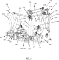
- FIG. 1 1 shows a perspective view of a device for applying force to a test vehicle according to an embodiment of the present invention.
- the device 100 serves to move a wheel adapter element 102 in multiple degrees of freedom.
- the device 100 can move the wheel adapter element 102 in six degrees of freedom.
- the device 100 can be part of a test bench for simulating chassis loads during driving.
- a test bench can have four devices according to FIG. 1 included, one device per wheel of the test vehicle.
- FIGS. 1 and 2 Only a single force application device will be described. The function of the remaining force application devices is analogous.
- the control of the actuators in the devices 100 of a test bench is synchronized with each other in order to generate the desired load on the chassis of the test vehicle.
- the test vehicle when using the device 100, the test vehicle is connected to the wheel adapter element 102.
- the chassis such as the front or rear axle and the shock absorbers, are connected to the wheel adapter element 102 before the test begins.
- the device 100 includes a first loading arrangement 108 for moving the wheel adapter element 102 in a first, translational direction.
- the first direction is a longitudinal direction, which, during operation, is parallel to the longitudinal axis of the test vehicle.
- the device 100 further includes a second loading arrangement 104 for moving the wheel adapter element 102 in a second, translational direction.
- the second direction is the vertical direction.
- the second, translational direction is accordingly substantially perpendicular to the first direction.
- a third loading arrangement 110 of the device 100 for applying force to a test vehicle serves to move the wheel adapter element 102 in a third, translational direction.
- the third direction is a lateral direction of movement.
- the third direction runs essentially perpendicular to the first and second directions.
- the first, second, and third loading arrangements 108, 104, 110 ensure that the wheel adapter element 102 is movable in all three translational directions of movement.
- the device 100 has a fourth loading arrangement for rotating the wheel adapter element 102.
- the fourth loading arrangement 106 can be used to rotate the wheel adapter element about the wheel axis A and thus simulate a braking force.
- the wheel axis A runs, in particular, parallel to the third direction. In the embodiment shown here, the wheel axis A extends in the lateral direction.
- the device 100 further comprises a fifth loading arrangement 111, which serves to introduce steering torques into the wheel adapter element 102.
- the steering torque is a rotation of the wheel adapter element 102 about a vertical axis (not shown) that runs through the center of the wheel adapter element 102 and intersects the wheel axis A perpendicularly.
- a camber moment is a rotation of the wheel adapter element 102 about a transverse axis perpendicular to the wheel axis A and the vertical axis (not shown), which runs parallel to the longitudinal axis of the test vehicle.
- first, second and fourth loading assemblies 108, 104, 106 are attached to a first anchorage 142.
- the third and fifth loading assemblies 110, 111 are attached to a second anchorage 144.
- the anchorages 142, 144 can be attached, for example, to a floor slab to dissipate the counterforces occurring during the test.
- Each of the loading assemblies 104, 106, 108, 110, 111 has at least one actuator 112, 118, 124, 132, 134, which is connected to the wheel adapter element 102 via a corresponding kinematics.
- the actuators 112, 118, 124, 132, 134 are all depicted as linear drives. These can be configured, for example, as hydraulic, electric, or pneumatic linear drives. However, other types of actuators are conceivable.
- each loading arrangement 104, 106, 108, 110, 111 each comprise at least one lever element that connects the actuator to a transmission element (here, a coupling rod) 114, 116, 122, 128, 138, 140.
- the transmission elements themselves are each connected at a first end to a lever of the loading arrangement and at an opposite, second end to the wheel adapter element.
- the transmission elements, designed as coupling rods, serve in particular to transmit the movement of the actuator to the wheel adapter element 102.
- the first loading arrangement 108 has a first actuator 118, which is connected via a lever element 120 to a transmission element 122 designed as a coupling rod.
- the lever element 120 is shown as a single-armed lever, which is pivoted about a pivot axis 152 ( FIG. 2 ) can be pivoted.
- the transmission element 122 of the first loading arrangement 108 is connected at a first end to a ball joint of a three-joint node 130. At an opposite, second end, the transmission element 122 is pivotally connected to the lever element 120.
- the transmission elements 114, 116, 122, 128, 138, 140 of the loading arrangements 104, 106, 108, 110, 111 are arranged orthogonally to one another. This position is referred to as the working position. In the working position, at least the transmission elements 114, 122, 128 of the first, second, and third loading arrangements 104, 108, 110 orthogonally aligned.
- the actuators 112, 118, 124 are each mounted between their end positions (between a fully extended and a fully retracted position).
- the actuator 112 of the second loading arrangement 104 i.e., the loading arrangement for initiating a vertical movement
- the wheel adapter element 102 In the rest position, the wheel adapter element 102 is accordingly in its lower end position.
- the lever elements 120 and 126 and the associated transmission elements 122, 128 of the first and third loading arrangements 108, 110 are inclined downward, as schematically illustrated by positions 120a and 126a.
- the transmission element 120 is aligned perpendicular to all remaining transmission elements 114, 116, 128, 138, 140.
- the first loading arrangement 108 serves to input movements in the longitudinal direction via the transmission element 122, which is aligned parallel to the longitudinal direction of the test vehicle.
- the second loading arrangement 104 also has an actuator 112.
- the second actuator 112 is connected via its drive rod to a lever element 113 of the second loading arrangement 104.
- the lever element 113 is designed as an angle lever.
- the drive rod of the second actuator 112 is connected at its distal end to a joint of a first lever arm of the lever element 113.
- a second lever arm of the lever element 113 is connected via a joint to a second end of the transmission element 114 of the second loading arrangement 104.
- the transmission element 114 of the second loading arrangement 104 is arranged between the three-joint node 130 and the lever element 113.
- the transmission element 114 of the second loading arrangement is also designed as a coupling rod in the embodiment shown here. Through the transmission element 114 of the second loading arrangement 104, a movement of the first actuator can be transmitted to the three-joint node 130 and the wheel adapter element 102 connected thereto.
- FIG. 1 shown second Loading arrangement 104 serves in particular for the vertical movement of the wheel adapter element 102.
- the third loading arrangement 110 has a third actuator 124, which is pivotally connected to a transmission element 128 via a lever element 126.
- the transmission element 128 is in the FIGS. 1 and 2 In the illustrated working position of the device 100, the transmission element 128 is arranged orthogonally to the transmission elements 114, 116, 122 of the first, second, and fourth loading arrangements.
- the transmission element 128 of the third loading arrangement 110 is also connected at a first end to the ball joint of the three-joint node 130. At a second, opposite end, the transmission element 128 is connected to the lever element 126.
- the lever element 126 is also designed as a single-armed lever in the embodiment illustrated here.
- the FIGS. 1 and 2 Finally, a fifth loading arrangement 111 can also be seen.
- the fifth loading arrangement 111 has a fifth actuator 132 and a sixth actuator 134.
- the fifth actuator 132 is connected to a lever element 137a via a transmission element 136a.
- the lever element 137a is designed, for example, as an angle lever.
- a second end of the lever element 137a is connected to a second transmission element 138.
- the second transmission element 138 of the fifth loading arrangement 111 connects the lever element 137a to an outer circumference of the wheel adapter element 102.
- the sixth actuator 134 is connected to a lever element 137b via a third transmission element.
- the lever element 137b is designed, for example, as an angle lever.
- a second end of the lever element 137b is connected to a fourth transmission element 140 of the fifth loading arrangement.
- the fourth transmission element 140 of the fifth loading arrangement 111 connects the lever element 137b to an outer circumference of the wheel adapter element 102.
- the second and fourth transmission elements 138, 140 of the fifth loading arrangement 111 run parallel to each other and parallel to the wheel axis A of the wheel adapter element 102.
- the two transmission elements 138, 140 are rod-shaped.
- the two transmission elements 138, 140 are each connected to the outer circumference of the wheel adapter element 102, in particular to diametrically opposite side surfaces of the wheel adapter element 102. Accordingly, by controlling the fifth and sixth actuators 132, 134 of the fifth loading arrangement 111 in opposite directions, a steering torque, i.e. a rotation about a vertical axis of the wheel adapter element 102, can be introduced into the wheel adapter element 102.
- FIGS. 1 and 2 It can also be seen that the three-joint node 130, in which the transmission elements 114, 122, 128 of the first, second, and third loading arrangements 104, 108, 110 are connected to one another, is arranged below the wheel element 102.
- the three-joint node 130 can accordingly be understood as the wheel contact point of the wheel adapter element 102.
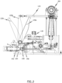
- FIG. 2 is a perspective sectional view of the FIG. 1 shown embodiment of the device 100.
- the FIG. 2 a sectional view through the first and second loading arrangements 108, 104.
- the first loading arrangement 108 serves in particular to move the wheel adapter element 102 in the longitudinal direction of the test vehicle.
- a movement of the first actuator 118 is transmitted to the lever element 120.
- the movement of the lever element 120 is finally transmitted to the wheel adapter element 102 via the transmission element 122, which is designed as a coupling rod.
- the lever element 120 is pivotable in particular about the pivot axis 152.
- positions 120a, 120b, 120c of the lever element 120 are schematically shown.
- a first position 120a the lever element 120 is pivoted clockwise.
- position 120a can be the position of the lever element 120 in the rest position, i.e. the lower end position, of the device 100.
- a second position 120b the lever element 120 is in the working position, i.e. the transmission elements 114, 122, 128 are aligned orthogonally to each other.
- the lever element 120 is counterclockwise Pivoted clockwise. This can, for example, be an upper end position of the device 100, in which the actuator 112 of the second loading arrangement 104 is fully extended.
- FIG. 2 Three positions 126a, 126b, 126c of the lever element 126 of the third loading arrangement 110 are shown schematically.
- a first position 126a the lever element 126 is pivoted counterclockwise, i.e., towards the wheel adapter element 102.
- Position 126a can be the position of the lever element 126 in the rest position, i.e., the lower end position, of the device 100.
- a second position 126b the lever element 126 is in the working position, i.e., the transmission elements 114, 122, 128 are aligned orthogonally to one another.
- a third position 126c the lever element 126 is pivoted clockwise, i.e., away from the wheel adapter element. This may be an upper end position of the device 100 in which the actuator 124 of the second loading arrangement 104 is fully extended.
- the positions of the device 100 and the associated lever elements 120, 126 shown above are only schematic and incomplete. It should be noted that the device is essentially infinitely adjustable and thus any further position between the positions shown in FIG. 2 indicated position.
- the holding device 150 described below allows the device 100 to be fixed in any desired position.
- the pivot axis 152 of the lever element 120 of the first loading arrangement 108 is connected to a brake disc segment 154.
- the brake disc segment 154 is part of a holding device 150, which is designed to fix the first loading arrangement 108 in any position, for example in the working position 120b, 126b.
- the holding device 150 has a fixing element 156 designed as a friction brake.
- the fixing element serves to activate the holding device as soon as the loading arrangement is in the desired position.
- the fixing element 156 can be brake shoes that selectively contact/clamp the brake disc segment 154.
- the holding device can also be designed differently.
- the holding device 150 shown in the embodiments is in FIG. 3 shown in detail.
- the brake disc segment 154 is arranged on the pivot axis 152 of the lever element 120 in such a way that it can be brought into contact with the brake shoes 156 in any position 120a, 120b, 120c of the lever element 120, and thus in any position of the first loading arrangement 108.
- a part of the brake disc segment is located between the brake shoes 156 at all times.
- FIG. 3 The position of the lever 120 or the brake disc segment 154 shown, for example, is the first position 120a.
- the invention is not limited to a brake disc segment. It can also be a brake disc that completely surrounds the pivot axis 152.
- FIG. 4 shows a schematic, perspective view of a brake assembly 200.
- the brake assembly 200 supports the fixing element, which is designed as a friction brake, and fastens it, for example, to the anchor 142.
- the brake assembly 200 has a bracket 212, which is fixedly connected to the anchor 142 or the base plate.
- the brake assembly further has first and second brake shoes 202, 204, which are configured to selectively contact the brake disc segment 154.
- the brake shoes 202, 204 can be moved by drive means 206, 208 in a known manner to generate a frictional force together with the brake disc segment 154.
- the first and second brake shoes 202, 204 are arranged on a carrier plate 210.
- the carrier plate 210 is connected to the holder 212 via elastic buffer elements 214, 216, 218, 220.
- the elastic buffer elements 214, 216, 218, 220 enable a relative movement between the carrier plate 210 and the holder 212. This results in, in particular, the brake shoes 202, 204, designed as friction brakes, being movable relative to the holder 212 in a plane parallel to the brake disc segment 154.
- an elastic deformation of the elastic buffer elements 214, 216 or the elastic buffer elements initially occurs. 218, 220, depending on the direction of rotation of the brake disc segment 154.
- the elastic buffer elements thus serve to gently absorb the movement of the load assembly 108. This protects, in particular, the chassis of the test vehicle under test.
- the holding device designed as a disc brake can also be used to gradually brake the brake disc segment 154 and thus the first loading arrangement 108.
- the brake shoes 202, 204 can act with full force on the brake disc segment 154, so that the loading arrangement 108 is fixed in the desired position.
- the control of the holding device takes place independently of the control of the loading arrangement 108. In particular, only activation of the drive elements 206, 208 is necessary to control the holding device.
- the loading assembly 108 can be held in the desired position by the holding device 150 alone, so that damage to the chassis or possible injuries can be effectively prevented.
- the holding device of the present invention is not limited to a disc brake according to the illustrated embodiments. Rather, a fixing element with pins for force-fitting the holding device to the loading arrangement or similar selective stops can also be used. Even in such an embodiment, it is preferred that elastic buffer elements are provided between the fixing element and a corresponding holder of the holding device in order to prevent an abrupt stopping of the movement of the first loading arrangement.
- each of the three translational loading arrangements 104, 108, 110 is provided with a separate holding device.
Landscapes
- Physics & Mathematics (AREA)
- General Physics & Mathematics (AREA)
- Braking Arrangements (AREA)
Applications Claiming Priority (1)
| Application Number | Priority Date | Filing Date | Title |
|---|---|---|---|
| DE102023131735.0A DE102023131735B3 (de) | 2023-11-14 | 2023-11-14 | Vorrichtung zur krafteinleitung in ein test-fahrzeug sowie prüfstand |
Publications (1)
| Publication Number | Publication Date |
|---|---|
| EP4556879A1 true EP4556879A1 (fr) | 2025-05-21 |
Family
ID=92909592
Family Applications (1)
| Application Number | Title | Priority Date | Filing Date |
|---|---|---|---|
| EP24202648.2A Pending EP4556879A1 (fr) | 2023-11-14 | 2024-09-25 | Dispositif pour l'introduction de force dans un objet à tester |
Country Status (5)
| Country | Link |
|---|---|
| US (1) | US20250155324A1 (fr) |
| EP (1) | EP4556879A1 (fr) |
| JP (1) | JP2025080768A (fr) |
| CN (1) | CN120008936A (fr) |
| DE (1) | DE102023131735B3 (fr) |
Citations (3)
| Publication number | Priority date | Publication date | Assignee | Title |
|---|---|---|---|---|
| US5465615A (en) * | 1994-04-28 | 1995-11-14 | Mts Systems Corporation | Loading assembly for a vehicle spindle test fixture |
| US5633464A (en) * | 1994-11-10 | 1997-05-27 | Mts Systems Corporation | Loading assembly for a vehicle spindle test fixture |
| DE10084957T1 (de) * | 1999-09-03 | 2002-11-07 | Mts System Corp | Belastungsanordnung für eine Fahrzeugachsen-Prüfvorrichtung |
Family Cites Families (1)
| Publication number | Priority date | Publication date | Assignee | Title |
|---|---|---|---|---|
| CN208705062U (zh) | 2018-08-30 | 2019-04-05 | 上海汽车集团股份有限公司 | 车辆悬架总成道路模拟系统 |
-
2023
- 2023-11-14 DE DE102023131735.0A patent/DE102023131735B3/de active Active
-
2024
- 2024-09-25 EP EP24202648.2A patent/EP4556879A1/fr active Pending
- 2024-11-05 CN CN202411566505.4A patent/CN120008936A/zh active Pending
- 2024-11-11 US US18/943,297 patent/US20250155324A1/en active Pending
- 2024-11-12 JP JP2024197106A patent/JP2025080768A/ja active Pending
Patent Citations (3)
| Publication number | Priority date | Publication date | Assignee | Title |
|---|---|---|---|---|
| US5465615A (en) * | 1994-04-28 | 1995-11-14 | Mts Systems Corporation | Loading assembly for a vehicle spindle test fixture |
| US5633464A (en) * | 1994-11-10 | 1997-05-27 | Mts Systems Corporation | Loading assembly for a vehicle spindle test fixture |
| DE10084957T1 (de) * | 1999-09-03 | 2002-11-07 | Mts System Corp | Belastungsanordnung für eine Fahrzeugachsen-Prüfvorrichtung |
Also Published As
| Publication number | Publication date |
|---|---|
| CN120008936A (zh) | 2025-05-16 |
| JP2025080768A (ja) | 2025-05-26 |
| US20250155324A1 (en) | 2025-05-15 |
| DE102023131735B3 (de) | 2025-01-02 |
Similar Documents
| Publication | Publication Date | Title |
|---|---|---|
| EP1998930B1 (fr) | Dispositif de positionnement | |
| EP0350608B1 (fr) | Procédé et dispositif d'essai d'axes de véhicules utilitaires avec des ressorts | |
| EP3084386B1 (fr) | Procédé et dispositif pour le réglage des paramètres de la géométrie de châssis des roues d'un véhicule | |
| AT517451B1 (de) | Prüfvorrichtung sowie Prüfstand mit einer derartigen Prüfvorrichtung | |
| DE3302557C2 (de) | Einrichtung zum Verhindern des Abhebens eines Kraftfahrzeuges beim Bremsen | |
| WO2011151342A1 (fr) | Banc d'essai de fonctionnement de véhicule | |
| DE3040355A1 (de) | Pruefstand | |
| DE102021125332B3 (de) | Antriebs- und Bremssystem für ein Kraftfahrzeug | |
| DE102010000884A1 (de) | Vorrichtung zum kippbaren Lagern einer Fahrzeugkabine eines Fahrzeuges an einem Fahrzeugaufbau mit einer Stabilisatoreinrichtung | |
| EP0422489B1 (fr) | Véhicule à moteur avec cabine basculante et dispositif de basculement | |
| DE102010000886A1 (de) | Vorrichtung zum kippbaren Lagern einer Fahrzeugkabine eines Fahrzeuges | |
| DE3809995C2 (fr) | ||
| DE102014201621B4 (de) | Verbundlenkerachse für Fahrzeuge | |
| EP0360179B1 (fr) | Banc d'essai à rouleaux pour véhicules | |
| DE102023131735B3 (de) | Vorrichtung zur krafteinleitung in ein test-fahrzeug sowie prüfstand | |
| EP1600756B1 (fr) | Dispositif pour la simulation de collision d'un véhicule | |
| DE102004063041A1 (de) | Fahrzeugfunktionsprüfstand | |
| AT526343B1 (de) | Lenkkraftmodul für einen Antriebsstrangprüfstand | |
| DE102020118085A1 (de) | Haltesystem und Positionierungssystem für einen Motorradprüfstand | |
| EP4556878A1 (fr) | Dispositif pour l'introduction de force dans un objet à tester | |
| DE202013100881U1 (de) | Verbundlenkerachse für Fahrzeuge | |
| DE102014008620A1 (de) | Fahrwerksystem eines Fahrzeuges und Verfahren zum Abheben wenigstens eines Fahrzeugrades eines Fahrzeuges | |
| AT526404B1 (de) | Fahrzeug | |
| DE102005051146B4 (de) | Verfahren und Prüfvorrichtung zum Prüfen und Einstellen des Lüftspiels einer Radbremse eines Kraftfahrzeuges | |
| DE102022212535B3 (de) | Prüfvorrichtung zum Prüfen eines Drehkranzlagers |
Legal Events
| Date | Code | Title | Description |
|---|---|---|---|
| PUAI | Public reference made under article 153(3) epc to a published international application that has entered the european phase |
Free format text: ORIGINAL CODE: 0009012 |
|
| STAA | Information on the status of an ep patent application or granted ep patent |
Free format text: STATUS: REQUEST FOR EXAMINATION WAS MADE |
|
| 17P | Request for examination filed |
Effective date: 20240925 |
|
| AK | Designated contracting states |
Kind code of ref document: A1 Designated state(s): AL AT BE BG CH CY CZ DE DK EE ES FI FR GB GR HR HU IE IS IT LI LT LU LV MC ME MK MT NL NO PL PT RO RS SE SI SK SM TR |