EP4556884A1 - Fortschrittliche probendickenmessanordnung und verfahren zur messung einer dicke einer probe bei kryogener temperatur mittels interferometrie unter verwendung eines kryostats - Google Patents
Fortschrittliche probendickenmessanordnung und verfahren zur messung einer dicke einer probe bei kryogener temperatur mittels interferometrie unter verwendung eines kryostats Download PDFInfo
- Publication number
- EP4556884A1 EP4556884A1 EP23209700.6A EP23209700A EP4556884A1 EP 4556884 A1 EP4556884 A1 EP 4556884A1 EP 23209700 A EP23209700 A EP 23209700A EP 4556884 A1 EP4556884 A1 EP 4556884A1
- Authority
- EP
- European Patent Office
- Prior art keywords
- tube
- sample
- cryostat
- arrangement
- thickness
- Prior art date
- Legal status (The legal status is an assumption and is not a legal conclusion. Google has not performed a legal analysis and makes no representation as to the accuracy of the status listed.)
- Withdrawn
Links
Images



Classifications
-
- G—PHYSICS
- G01—MEASURING; TESTING
- G01N—INVESTIGATING OR ANALYSING MATERIALS BY DETERMINING THEIR CHEMICAL OR PHYSICAL PROPERTIES
- G01N1/00—Sampling; Preparing specimens for investigation
- G01N1/28—Preparing specimens for investigation including physical details of (bio-)chemical methods covered elsewhere, e.g. G01N33/50, C12Q
- G01N1/42—Low-temperature sample treatment, e.g. cryofixation
-
- G—PHYSICS
- G01—MEASURING; TESTING
- G01B—MEASURING LENGTH, THICKNESS OR SIMILAR LINEAR DIMENSIONS; MEASURING ANGLES; MEASURING AREAS; MEASURING IRREGULARITIES OF SURFACES OR CONTOURS
- G01B11/00—Measuring arrangements characterised by the use of optical techniques
- G01B11/02—Measuring arrangements characterised by the use of optical techniques for measuring length, width or thickness
- G01B11/06—Measuring arrangements characterised by the use of optical techniques for measuring length, width or thickness for measuring thickness ; e.g. of sheet material
- G01B11/0616—Measuring arrangements characterised by the use of optical techniques for measuring length, width or thickness for measuring thickness ; e.g. of sheet material of coating
- G01B11/0675—Measuring arrangements characterised by the use of optical techniques for measuring length, width or thickness for measuring thickness ; e.g. of sheet material of coating using interferometry
-
- G—PHYSICS
- G01—MEASURING; TESTING
- G01B—MEASURING LENGTH, THICKNESS OR SIMILAR LINEAR DIMENSIONS; MEASURING ANGLES; MEASURING AREAS; MEASURING IRREGULARITIES OF SURFACES OR CONTOURS
- G01B9/00—Measuring instruments characterised by the use of optical techniques
- G01B9/02—Interferometers
- G01B9/02015—Interferometers characterised by the beam path configuration
- G01B9/02024—Measuring in transmission, i.e. light traverses the object
-
- G—PHYSICS
- G01—MEASURING; TESTING
- G01B—MEASURING LENGTH, THICKNESS OR SIMILAR LINEAR DIMENSIONS; MEASURING ANGLES; MEASURING AREAS; MEASURING IRREGULARITIES OF SURFACES OR CONTOURS
- G01B9/00—Measuring instruments characterised by the use of optical techniques
- G01B9/02—Interferometers
- G01B9/02041—Interferometers characterised by particular imaging or detection techniques
- G01B9/02047—Interferometers characterised by particular imaging or detection techniques using digital holographic imaging, e.g. lensless phase imaging without hologram in the reference path
Definitions
- the present invention relates to a sample thickness measuring arrangement and to a method for measuring a thickness of a sample to be examined using e.g. cryo electron microscopy. Furthermore, the invention relates to a cryostat to be used in such arrangement or method.
- Electron microscopy may be used to examine extremely small structures or particles for example in a nanometre range.
- cryo electron microscopy In order to enable examining biological samples such as biological cells, cryo electron microscopy (CryoEM) has been developed.
- Cryo electron microscopy is a form of transmission electron microscopy (TEM), in which biological samples are examined at cryogenic temperatures of below -123 °C (150 K).
- TEM transmission electron microscopy
- samples are generally quick-frozen and thereby vitrified before being inserted into a transmission electron microscope.
- CryoEM data are obtained from sample particles embedded in a vitrified solution such as amorphous ice set on a CryoEM sample holder.
- the CryoEM sample holder may consist for example of a 3mm diameter 10 to 20 micrometre thickness metal grid made e.g. of copper, gold or another metal and being covered for example with a holey carbon film.
- the carbon film may have a thickness of for example about 10 nm and may include a matrix of micron-sized holes that holds a sample solution.
- the sample solution may typically comprise the samples to be examined and may further include water, salts and/or cryo-protectant.
- the sample solution may be dispensed on a grid of a CryoEM sample holder, may then be blotted and may finally be vitrified by rapidly cooling it for example in liquid ethane.
- An optimal sample thickness may be around 100 nm, which may allow having in the holes of the CryoEM sample holder a single layer of sample particles embedded in the vitrified ice.
- the applicant of the present application has developed a cryostat and a sample thickness measuring arrangement using such cryostat as well as a method for measuring a thickness of a sample using such cryostat. Details of such approach have been disclosed in the prior patent application WO 2020/058140 A1 . Further Information about a technical background regarding CryoEM and its requirements as well as details about the prior approach including the cryostat and its application in the sample thickness measuring arrangement and method are given in the prior patent application.
- the present application relates to a further development of such prior approach. It is to be noted that details disclosed with regards to embodiments of the prior approach may be applied or adopted to embodiments of the further development described in the present application. Accordingly, the entire content of the prior application shall be incorporated herein by reference.
- an advanced sample thickness measuring arrangement and for a method for measuring a thickness of a sample may enable measuring a thickness of the sample with enhanced precision and/or enhanced reproducibility and/or which may thereby enable simple, reliable and/or cost effective sample preparation and/or quality control e.g. for application in CryoEM.
- a cryostat which may be beneficially applied in such sample thickness measuring arrangement or method for measuring a thickness of a sample.
- a cryostat comprising a coolant reservoir for storing liquid coolant and a sample observation unit for observing characteristics of a sample
- the coolant reservoir comprises a vessel enclosing a storage volume with walls of the vessel being thermally insulated with a thermal reservoir insulation layer such as to enable storing liquid coolant at temperatures below 150 K.
- the sample observation unit comprises a high thermal conductivity tube, a thermal tube insulation layer and a window arrangement.
- the tube has tube walls enclosing a tube volume including an observation volume.
- the tube is provided with a sealing arrangement for tightly sealing at least one of a distal end and a proximal end of the tube such as to prevent gas circulation through the tube.
- the tube walls comprise a highly thermally conductive material.
- the distal end of the tube is arranged within the storage volume of the coolant reservoir such as to make direct contact between the tube walls and liquid coolant stored in the coolant reservoir.
- the tube has two lateral openings in its tube walls at opposing sides with regards to the observation volume. At least portions of the tube walls are covered at their external side with the thermal tube insulation layer.
- the thermal tube insulation layer has two openings adjacent to the openings in the tube walls.
- the window arrangement comprises two opposing windows with panes, each pane being arranged at one of the openings in the thermal insulation layer. The panes are transparent to laser light.
- a sample thickness measuring arrangement comprises a cryostat according to an embodiment of the first aspect of the invention and furthermore comprises a sample thickness measuring unit being arranged and configured for transmitting a laser beam through the window arrangement of the sample observation unit and for determining the sample thickness based on interferometry measurements with the transmitted laser beam.
- a method for measuring a thickness of a sample comprises at least the following steps, preferably in the indicated order: a cryostat according to an embodiment of the first aspect of the invention is provided.
- the sample is inserted into the observation volume of the sample observation unit using e.g. a gripper or tweezer.
- a low temperature coolant gas flow through the tube of the sample observation unit of the cryostat is prevented.
- the thickness of the sample is measured by transmitting a laser beam through the window arrangement of the sample observation unit and determining the sample thickness based on interferometry measurements with the transmitted laser beam.
- sample preparation may be essential to obtain good CryoEM measurement results.
- criteria including, inter-alia, particle distribution, particle orientation, etc.
- a correct sample thickness may be a mandatory prerequisite.
- sample preparation process may include the interferometric measurement of the thickness of the sample during the preparation phase and after sample vitrification.
- optical thickness measurement techniques using interferometry measurements are in principle able to provide very high precision down to a nanometer range, these measurement techniques may be problematic when applied at cryogenic temperatures. Particularly, it has been found that even slight temperature fluctuations, temperature inhomogeneities and/or temperature gradients may significantly influence the accuracy of such optical thickness measurement techniques.
- the cryostat comprised a coolant reservoir and a sample observation unit.
- the coolant reservoir may serve for storing liquid coolant such as liquid nitrogen to be used for keeping the sample at cryogenic temperatures at about or below 150 K in the observation volume.
- the sample observation unit may be specifically adapted for observing characteristics of the sample, such observed characteristics possibly allowing deriving information about the thickness of the sample.
- the sample observation unit comprises a tube enclosing the observation volume and being thermally insulated by a thermal tube insulation layer.
- the tube as well as the insulation layer comprise lateral openings at opposing sides with regards to the observation volume such that a laser beam may be transmitted through the openings and through the intermittent observation volume. Using such laser beam, interferometry thickness measurements may be made for determining the thickness of the sample arranged in the observation volume. Furthermore, in order to prevent thermal losses or thermal disturbances through the openings, a window arrangement comprising opposing thick panes is provided, each pane being arranged such as to cover one of the openings in the thermal insulation layer.
- the tube in the sample observation unit shall be open both at its distal end as well as at its proximal end, as it was assumed that a gentle gas flow of cryogenic gas at very low temperatures should be established between the tube's distal end being arranged within the storage volume of the coolant reservoir and the tube's proximal end.
- a gentle gas flow of cryogenic gas at very low temperatures should be established between the tube's distal end being arranged within the storage volume of the coolant reservoir and the tube's proximal end.
- such gentle cryogenic gas flow may help keeping the sample arranged in the observation volume at cryogenic temperatures during the interferometry thickness measurements, as the observation volume is arranged between the tube's distal and proximal ends such that the cryogenic gas flows along the sample therein.
- cryogenic gas flow may induce some negative effects, For example, such cryogenic gas flow may at least slightly disturb or degrade the interferometry thickness measurements.
- the tube with a specific sealing arrangement.
- Such sealing arrangement is configured for tightly sealing the tube's distal end and/or the tube's proximal end in order to thereby prevent any substantial gas circulation through the tube. Accordingly, with the sealing arrangement being established at least at one of the ends of the tube, any gas flow through the tube is prevented, thereby also preventing any disturbances induced by such gas flow.
- the sealing arrangement is arranged at or proximal to the proximal end of the tube and is thermally isolated from the tube.
- the sealing arrangement is provided at the tube's proximal end being further distant from the coolant reservoir in comparisons to the tubes distal end.
- the sealing arrangement is generally easily accessible from outside the coolant reservoir and is not submitted to the very low cryogenic temperatures within the coolant reservoir.
- the sealing arrangement is not in direct contact with the tube but is spaced therefrom and is thermally isolated from the tube. Thereby, any influence of the sealing arrangement to thermal conditions at the tube are minimized.
- a distance between the sealing arrangement and the tube may be at least a few millimeters, e.g. between 2 mm and 100 mm, preferably between 5 mm and 50 mm.
- a gap between the sealing arrangement and the tube may be filled with a thermally insulating material which may be same or similar to material of the thermal tube insulation layer.
- Such measures include, inter-alia, providing walls of the tube with a highly thermally conductive material.
- a highly thermally conductive material generally has a thermal conductivity being at least one or several orders of magnitude larger than a thermal conductivity of the material forming the thermal tube insulation layer.
- the tube walls may be made with a metal such as preferably copper having superior thermal conductivity. Accordingly, thermal energy is conducted along the tube with low thermal resistance.
- the distal end of the tube is arranged within the storage volume of the coolant reservoir such as to establish a direct contact between the tube walls and the liquid coolant stored in the coolant reservoir.
- the distal end of the tube is cooled to cryogenic temperatures by the liquid coolant in a very efficient way. Furthermore, due to the superior thermal conductivity of the tube walls, the cryogenic temperatures are transmitted from the tube's distal end towards a portion of the tube enclosing the observation volume. As an overall result, the observation volume may be surrounded by tube walls being stably held at cryogenic temperatures and such cryogenic temperatures may be transferred to the sample accommodated within the observation volume. Accordingly, a thickness of such stably cooled sample may be reliably measured using interferometry thickness measurement techniques.
- the cryostat further comprises a sample holder with a gripper being arranged and configured for gripping and holding a sample within the observation volume of the sample observation unit at a location within the tube between the opposing panes.
- the cryostat may be provided with a sample holder which is configured for temporarily gripping the sample being originally be stored e.g. in or at the storage volume of the coolant reservoir, then displacing the sample holder together with the sample in order to arrange and hold the sample within the observation volume of the sample observation unit during interferometry thickness measurements, before finally releasing the sample again.
- a gripper activated between a closed gripping configuration in which it may grip a sample and an opened releasing configuration in which it may release the sample.
- the gripper may be a tweezer or pincer.
- the gripper may be made with a metal.
- a gripper made with metal or, preferably, completely consisting of metal may have a high thermal inertia. Due to such high thermal inertia, the temperature of the gripper as well as of the sample held by the gripper may be very stable.
- the gripper may be configured such as to mainly make thermal contact with the tube upon being inserted within the tube.
- characteristics of the gripper such as its material, its geometry, its surface characteristics, etc. may preferably be set such that any exchange of thermal energy to and from the gripper is mainly established with regards to the tube and any further thermal energy exchanges with for example other components of the cryostat are of minor influence.
- the thermal energy exchanges between the tube and the gripper may be based on thermal conductance and/or thermal radiation exchange and/or thermal convection. Accordingly, due to such major thermal contact with the tube, the gripper together with the gripped sample are generally stably thermalized to the cryogenic temperatures of the tube.
- the gripper may be configured such as to make direct mechanical contact with the tube upon being inserted within the tube.
- a geometry of the gripper may be adapted to a geometry of the tube such that direct mechanical contact between the gripper and the tube at least along portions of a surface of the gripper is established upon the gripper being accommodated within the tube, particularly within the observation volume in the tube. Due to such direct mechanical contact, thermal energy may be directly and efficiently transmitted between the tube and the gripper due to thermal conductance.
- the gripper together with the gripped sample are generally stably thermalized to the cryogenic temperatures of the tube.
- the sample holder further comprises a handling extension for handling and displacing the gripper within the tube.
- the handling extension extends through the sealing arrangement. Furthermore, at least a portion of the handling extension extending through the sealing arrangement is made with a thermally insulating material.
- handling extension is provided with or attached to an additional component referred to herein as handling extension.
- handling extension may be an elongate component which, at its distal end, is fixed to the gripper such that, using the handling extension, the gripper may be handled and displaced within the tube.
- Such handling extension is configured such that it extends through the sealing arrangement provided preferably close to the proximal end of the tube. Accordingly, the handling extension may extend, with a proximal portion thereof, in a volume outside the tube and proximal with regards to the sealing arrangement and, with a distal portion thereof, in a volume inside the tube and distal with regards to the sealing arrangement. An intermediate portion of the handling extension then extends through the sealing arrangement.
- the sealing arrangement as well as the intermediate portion of the handling extension are configured such that the sealing arrangements together with the handling extension may tightly seal the distal end of the tube such as to prevent any gas flow escaping from the tube and therefore also preventing any gas circulation through the tube.
- the sealing arrangement and the handling extension are configured such that the handling extension may be displaced in a sliding up or down motion relative to the sealing arrangement.
- the handling extension extending through the sealing arrangement or, preferably, the entire handling extension shall be made with or consists of a thermally insulating material having a thermal conductivity being substantially lower, preferably being one or several orders of magnitude lower, than the thermal conductivity of the material of the gripper. Due to such low thermal conductivity, substantially no thermal energy is transferred via the handling extension to the gripper, thereby stabilising the gripper's temperature.
- At least a portion of the handling extension extending through the sealing arrangement or, preferably, the entire handling extension is made with or consists of a non-metal material such as preferably a plastic material.
- Such non-metal or plastic material generally has a low thermal conductivity and/or a low thermal capacity and therefore supports preventing any thermal energy transfer from or via the handling extension to the gripper, thereby stabilising the gripper's temperature.
- any heat transfer between for example a room-temperature environment surrounding the proximal portion of the handling extension outside the cryostat and a cryo-temperature environment surrounding the distal portion of the handling extension inside the cryostat may be limited.
- the entire elongate handling extension or at least portions thereof may be made with epoxy.
- the cryostat further comprises a chamber surrounding a portion of the handling extension positioned external to the tube.
- the chamber may comprise chamber walls enclosing the proximal portion of the handling extension protruding from the tube.
- the chamber walls may be laterally spaced apart from the handling extension such as to provide for thermal insulation.
- the chamber may avoid ambient air from entering into contact with the proximal portion of the handling extension in order to prevent, inter-alia, any condensation at the cool handling extension.
- the cryostat further comprises a gas supply arrangement configured for supplying gas to a volume adjacent to the sealing arrangement.
- the gas supply arrangement may supply dry gas such as nitrogen (N2) for example to the chamber surrounding the proximal portion of the handling extension just above the sealing arrangement.
- dry gas such as nitrogen (N2)
- N2 dry gas
- the cryostat further comprises a door arrangement for selectively opening and closing an access to the distal end of the tube.
- the door arrangement may be displaced between a closed configuration, in which it tightly covers and closes the distal end of the tube, and an opened configuration, in which it leaves the distal end of the tube open and accessible.
- Such door arrangement may for example serve as a trapdoor at the distal end of the tube which may selectively limit any gas flow from entering the tube and/or circulating throughout the tube.
- the door arrangement when being in its closed configuration, may support establishing a stable temperature within the tube, particularly within the observation volume accommodating the sample.
- the door arrangement In its open configuration, the door arrangement may allow introducing and releasing samples to and from the tube through the distal end of the tube.
- Fig. 1 shows a sample thickness measuring arrangement 1 including a cryostat 3. Additionally to the cryostat 3, the sample thickness measuring arrangement 1 comprises a sample thickness measuring unit 5.
- the sample thickness measuring unit 5 is configured for generating a laser beam 9 to be transmitted through a transparent sample 49 and for measuring phase shifts in the laser beam 9 after transmission through the sample 49, in order to thereby derive information about the thickness of the sample 49.
- Such sample thickness measuring unit 5 could be a commercial digital holographic microscope (DHM).
- Digital holographic microscopy is a kind of digital holography applied to microscopy. Digital holographic microscopy distinguishes itself from other microscopy methods by not recording a projected image of the object but, instead, digitally recording the light wave front information originating from the object as a hologram. From such hologram, a computer may calculate the object image by using a numerical reconstruction algorithm.
- Other closely related microscopy methods to digital holographic microscopy are interferometric microscopy, optical coherence tomography and diffraction phase microscopy. Common to all those methods is a use of a reference wave front to obtain amplitude and phase information.
- the information is recorded on a digital image sensor or by a photodetector from which an image of the object may be created or reconstructed by a computer.
- a digital image sensor or by a photodetector from which an image of the object may be created or reconstructed by a computer.
- no reference wave front is used but only intensity information is recorded and essential information about the object is generally lost.
- DHM In DHM, it is generally necessary to create interference patterns, i.e. a hologram. Accordingly, the illumination used in DHM needs to be coherent.
- a laser beam is generally applied as an illumination source.
- the laser beam is typically split into an object beam and a reference beam.
- the expanded object beam illuminates the sample to create the object wave front.
- the object and reference wave fronts are joined e.g. by a beam splitter to interfere and create the hologram.
- a computer may act as a digital lens and calculate a viewable image of the object wave front by using a numerical reconstruction algorithm.
- DHM may be used to provide a 2-dimensional image of the transparent object comprising, inter alia, information about the local thicknesses of the object.
- the DHM may additionally comprise an objective including a lens such that the grid may be directly imaged.
- the sample thickness measuring unit 5 comprised in the sample thickness measuring arrangement 1 is only visualized very schematically. It comprises a laser 7 emitting the laser beam 9 and a light detector 11.
- the laser beam 9 has a relatively broad beam width and the light detector 11 comprises several detector pixels such as to generate 2-dimensional information regarding an amplitude and phase of detected laser light.
- the laser 7 as well as the light detector 11 are connected to a computing unit 13 which may generate 2-dimensional images or maps based on the information received by the light detector 11, such images or maps representing local widths at various locations throughout the sample 49. Such images or maps may be output at an output interface 15. Accordingly, the images or maps may be transmitted to other devices such as, for example, a CryoEM or a control computer of a sample preparation machine.
- CryoEM data may only be obtained from particles embedded in a vitrified solution, i.e. in amorphous ice.
- a vitrified solution i.e. in amorphous ice.
- the samples should remain under 150 K, i.e. the temperature where vitrified ice transforms to hexagonal, cubic or crystalline ice.
- the prepared sample grids are typically stored in liquid nitrogen at 77.36 K. Thickness measurements should then be operated in cryogenic conditions.
- the cryostat 3 comprises a coolant reservoir 17 and a sample observation unit 19.
- the coolant reservoir 17 comprises a vessel 21 enclosing a storage volume 23. Therein, walls 25 of the vessel 23 are thermally insulated with a thermal reservoir insulation layer 27. Due to such insulation, liquid coolant 29 may be stored within the coolant reservoir 17 at cryogenic temperatures below 150 K.
- the sample observation unit 19 comprises a tube 31, a thermal tube insulation layer 33 and a window arrangement 35.
- the tube 31 comprises tube walls 32. According to the prior approach, the tube 31 is open both at its distal end 37 and at its proximal end 39.
- the distal end 37 of the tube 31 is arranged within the storage volume 23 of the coolant reservoir 17 such that portions of the liquid coolant 29 may enter the inside of the tube 31 and/or thermally contact the distal end 37 of the tube 31. Accordingly, liquid coolant 29 may cool the tube 31 and may partially evaporate such as to establish a gentle flow of low-temperature coolant gas through the tube 31.
- the tube 31 is made of a metal such as copper having a high thermal conductivity.
- An external side of the tube 31 is covered with the thermal tube insulation layer 33 such as to minimize any thermal losses. Accordingly, thermal losses, thermal fluctuations and/or thermal gradients throughout the tube 31 may be minimized.
- the tube 31 comprises two lateral openings 41.
- the lateral openings 41 are arranged at opposite sides of the tube 31 and enclose an observation volume 43 in between. Adjacent to the openings 41 in the tube 31, openings 45 are also provided within the thermal tube insulation layer 33.
- the window arrangement 35 comprises two thick panes 47 of glass or plexiglass. These panes 47 have a geometry complementary to the openings 45 in the thermal tube insulation layer 33 and therefore fill and thermally isolate these openings 45 in the region of the window arrangement 35.
- a solution comprising the samples 49 is dispensed on a grid 50 and is then vitrified e.g. in liquid ethane.
- the grid 50 with the vitrified samples 49 is then introduced into the observation volume 43 in the tube 31 of the cryostat 3.
- digital holographic microscope measurements may be performed for obtaining 2-dimensional information of thicknesses of the samples 49.
- a critical point observed in the applicant's prior approach may be the technique used to hold the samples 49 or, more precisely, the grid 50 with these samples 49, and to introduce it into the observation volume 43 in the tube 31.
- a sample holder 53 comprises tweezers 51 for holding and, optionally, displacing the grid 50 with the samples 49. Even though such tweezers 51 may have thin tips, it was observed in the prior approach that metallic tweezers 51 may drive enough heat to the samples 49 to modify a density of the coolant gas flow around the grid 50 and to, thereby, alter the thickness measurements. Accordingly, in the prior approach, measures where realized for minimizing thermal influences created by the sample holder 53.
- tweezers 51 made with plastics (e.g. glass loaded PEEK) have been used for holding the grid 50 with the samples 49.
- tweezers 51 may have a stabilizing core 55 being mechanically stable.
- core 55 may be made from glass.
- a surface of this core 55 may be covered with an outer sheath 57 of plastics.
- the creation of a thickness map of the grid 50 comprising the samples 49 with acceptable noise was possible.
- the sample observation unit 19 of the cryostat 3 and coupling such sample observation unit 19 to the sample thickness measuring unit 5 comprising a commercial digital holographic microscope it was shown to be possible to measure the thickness of a vitrified sample 49 on a CryoEM grid 50 with a precision of a few nanometers and to produce a sample thickness map over a whole grid 50.
- Such thickness map could be used to reject grids 50 with inadequate sample thickness and/or to directly access areas of optimal sample thicknesses during CryoEM analysis. Consequently, the proposed system could make CryoEM pipelines, comprising sample preparation, followed by screening and then followed by data collection, more efficient and CryoEM platforms more productive.
- the proposed approach could be realized as a stand-alone machine to control the quality of already prepared sample grids.
- a flexible inspection unit could be provided that could be adapted to existing in-line sample preparation machines.
- Fig. 2 shows a sample thickness measuring arrangement 1 with a cryostat 3 including a coolant reservoir 17 storing liquid coolant 29 at cryogenic temperatures and a sample observation unit 19 for observing characteristics of a sample 49.
- Fig. 3 shows a cross-sectional view of the sample thickness measuring arrangement 1 along a cutting plane "X" in an x-z-direction as indicated in Fig. 2 .
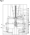
- Fig. 4 visualizes an enlarged portion indicated with "A” in Fig. 3 .
- Fig. 5 visualizes another enlarged portion indicated with "B” in Fig. 3 , however taken in a cutting plane "Y" in a y-z-direction as indicated in Fig. 2 .
- the coolant reservoir 17 comprises a vessel 21 enclosing a storage volume 23. Walls 25 of the vessel 21 are thermally insulated by a thermal reservoir insulation layer 27. A plurality of samples 49 is arranged on a carousel 59 which is accommodated within the coolant reservoir 17 in order to keep the samples 49 at cryogenic temperatures below 150 K.
- the sample observation unit 19 comprises a tube 31 having tube walls 32.
- the tube walls 32 enclose an inner tube volume.
- such tube volume includes an observation volume 43 in which the sample 49 is to be accommodated in order to conduct thickness measurements thereof.
- a thermal tube insulation layer 33 made with a thermally insulating material such as a foam covers and thermally insulates an outer circumference of the tube 31.
- the tube 31 has lateral openings 41 in its tube walls 32 at opposing sides with regards to the observation volume 43. Furthermore, the thermal tube insulation layer 33 comprises corresponding openings 45 adjacent to these openings 41 in the tube walls 32. Therein, a window arrangement 35 is formed and includes two opposing panes 47 arranged in the openings 45 in the thermal insulation layer 33. These panes 47 are optically transparent such that light of a laser beam 9 may be transmitted through the panes 47, through the openings 41 in the tube walls 32 and finally through the observation volume 43 with the sample 49 arranged therein.
- the tube 31 is no more open at its proximal end 39 and at its distal end 37 and no more gas flow is allowed through the tube 31.
- any substantial gas flow or gas circulation through the tube 31 is blocked by closing and sealing the tube 31 at least at one of its ends 37, 39.
- the tube 31 is provided with a sealing arrangement 65.
- such sealing arrangement 65 is arranged proximal to and spaced from the proximal end 39 of the tube 31.
- the sealing arrangement 65 is thermally isolated from the tube 31 due to a portion of the thermal tube insulation layer 33 being arranged between both components.
- the sealing arrangement 65 is configured such as to tightly seal a gas communication channel at the proximal end 39 of the tube 31 such that no substantial gas flow may be established along the inner volume of the tube 31. Due to blocking such gas flow, the sample 49 arranged in the observation volume 43 is not affected by any gas flow and may therefore be held in a thermally and/or mechanically stable condition.
- the tube walls 32 are made with a thermally highly conductive metal such as copper. Furthermore, the distal end 37 of the tube 31 is arranged within the storage volume 23 of the coolant reservoir 17 such as to establish a direct contact between the metallic tube walls 32 and the liquid coolant 29 in the coolant reservoir 17.
- the tube walls 32 are provided at the tube's distal end 37 with an elongate protrusion forming a plunger 79 which may dip directly into the liquid coolant 29. Due to such direct contact with the liquid coolant 29 and the superior thermal conductivity of the tube walls 32, stable thermal conditions at cryogenic temperatures may be established throughout the tube 31 and its inner volume including the observation volume 43.
- the cryostat further comprises a sample holder 53 including a gripper 61.
- Such gripper 61 may selectively grip and release a sample 49.
- the gripper 61 is connected with a handling extension 63 for handling and displacing the gripper 61 within the tube 31. Accordingly, using the sample holder 53, the gripper 61 may be displaced with the handling extension 63 such as to protrude from the distal end 37 of the tube 31 for gripping one of the samples 49 arranged on the carousel 59 and to then displace the gripper 61 together with the sample 49 along the inner volume of the tube 31 until arriving at the observation volume 43. The gripper 61 may then hold the sample 49 stably while the thickness of the sample 49 is measured. Subsequently, the gripper 61 may be displaced again towards the carousel 59 and release the sample 49.
- the entire gripper 61 or at least a lower part of the gripper 61 coming into direct contact with the sample 49 is made with metal having a high thermal capacity. Accordingly, thermal inertia of the gripper 61 helps keeping the sample 49 at stable thermal conditions while measuring its thickness.
- the gripper 61 is preferably configured such that its temperature is mainly influenced due to a thermal contact with the tube 31 and other thermal influences are negligible.
- the geometry of the gripper 61 may be adapted such that direct mechanical contact with the tube 31 is established upon the gripper 61 being inserted within the tube 31 at least along partial surface areas of the gripper 61. Nevertheless, there should be sufficient lateral play between the outer circumference of the gripper 61 and the inner circumference of the tube 31 in order to allow smooth displacement of the gripper 61 longitudinally along the tube 31.
- the gripper 61 may be configured for establishing intense thermal radiation exchange with the tube 31.
- the handling extension 63 has a rod-like elongate form and extends from its lower end connected to the gripper 61 and being arranged within the tube 31 to its upper end being arranged outside the tube 31 and preferably being accessible from outside the cryostat 3. Accordingly, the handling extension 63 may be used by a displacing mechanism arranged outside the cryostat 3 for displacing the gripper 61 throughout the tube 31 inside the cryostat 3 and/or for selectively activating a gripping action or a releasing action of the gripper 61.
- the handling extension 63 extends through the sealing arrangement 65.
- the sealing arrangement 65 may comprise a sealing ring enclosing the handling extension 63 such as to form a sliding seal.
- the handling extension 63 may then be displaced longitudinally relative to the sealing arrangement 65 while the sliding seal slides along a circumferential surface of the handling extension 63 and hermetically separates a volume distal from the sealing arrangement 65 from a volume proximal from the sealing arrangement 65.
- the handling extension 63 is made with a non-metal material such as plastics.
- the handling extension 63 may be made with epoxy. Due to the generally very low thermal conductivity of such plastic materials, any heat transfer along the handling extension 63 may be limited. Accordingly, the handling extension 33 helps thermally insulating the gripper 61 and its gripped sample 49 being at cryogenic temperatures from an environment being for example at room-temperature.
- the cryostat 3 is provided with a chamber 67 surrounding a portion of the handling extension 63 positioned external to the tube 31.
- a gas supply arrangement 69 is provided at the cryostat 3.
- the gas supply arrangement 69 includes a gas inlet 71 accessible from outside the cryostat 3 and a gas outlet 73 arranged close to the sealing arrangement 65. Accordingly, the gas supply arrangement 69 may supply gas to a volume adjacent to the sealing arrangement 65. Thereby, dry gas such as nitrogen gas may be blown along the sealing arrangement 65 in order to thereby avoid any condensation and/or freezing of the gripper 61 and/or of the handling extension 63. Furthermore, by introducing nitrogen gas from the gas outlet 73 within a chamber just above the sealing arrangement 65, ambient air may be prevented from entering the tube 31.
- the cryostat 3 further comprises a door arrangement 75 for selectively opening and closing an access to the distal end 37 of the tube 31.
- a door arrangement 75 may comprise a door cover plate 77 which may be displaced between an open configuration in which the distal end 37 of the tube 31 remains open and a closed configuration in which the door cover plate 77 covers the distal end 37 of the tube 31.
- the door arrangement 75 prevents any cryogenic gas from entering the tube 31 and therefore helps avoiding any gas flow throughout the tube 31.
Landscapes
- Physics & Mathematics (AREA)
- General Physics & Mathematics (AREA)
- Health & Medical Sciences (AREA)
- Life Sciences & Earth Sciences (AREA)
- Chemical & Material Sciences (AREA)
- Analytical Chemistry (AREA)
- Biochemistry (AREA)
- General Health & Medical Sciences (AREA)
- Immunology (AREA)
- Pathology (AREA)
- Investigating Or Analyzing Materials Using Thermal Means (AREA)
Priority Applications (3)
| Application Number | Priority Date | Filing Date | Title |
|---|---|---|---|
| EP23209700.6A EP4556884A1 (de) | 2023-11-14 | 2023-11-14 | Fortschrittliche probendickenmessanordnung und verfahren zur messung einer dicke einer probe bei kryogener temperatur mittels interferometrie unter verwendung eines kryostats |
| PCT/EP2024/080730 WO2025103771A1 (en) | 2023-11-14 | 2024-10-30 | Advanced sample thickness measuring arrangement and method for measuring a thickness of a sample at cryogenic temperature by interferometry using a cryostat |
| AU2024382780A AU2024382780A1 (en) | 2023-11-14 | 2024-10-30 | Advanced sample thickness measuring arrangement and method for measuring a thickness of a sample at cryogenic temperature by interferometry using a cryostat |
Applications Claiming Priority (1)
| Application Number | Priority Date | Filing Date | Title |
|---|---|---|---|
| EP23209700.6A EP4556884A1 (de) | 2023-11-14 | 2023-11-14 | Fortschrittliche probendickenmessanordnung und verfahren zur messung einer dicke einer probe bei kryogener temperatur mittels interferometrie unter verwendung eines kryostats |
Publications (1)
| Publication Number | Publication Date |
|---|---|
| EP4556884A1 true EP4556884A1 (de) | 2025-05-21 |
Family
ID=88833613
Family Applications (1)
| Application Number | Title | Priority Date | Filing Date |
|---|---|---|---|
| EP23209700.6A Withdrawn EP4556884A1 (de) | 2023-11-14 | 2023-11-14 | Fortschrittliche probendickenmessanordnung und verfahren zur messung einer dicke einer probe bei kryogener temperatur mittels interferometrie unter verwendung eines kryostats |
Country Status (3)
| Country | Link |
|---|---|
| EP (1) | EP4556884A1 (de) |
| AU (1) | AU2024382780A1 (de) |
| WO (1) | WO2025103771A1 (de) |
Citations (4)
| Publication number | Priority date | Publication date | Assignee | Title |
|---|---|---|---|---|
| DE2704300A1 (de) * | 1976-02-06 | 1977-08-11 | Reichert Optische Werke Ag | Verfahren und vorrichtung zur herstellung von praeparaten fuer die mikroskopie, insbesondere elektronenmikroskopie aus nativen histologischen objekten sowie physikochemisch aehnlichen produkten durch kryofixation |
| JP2016183976A (ja) * | 2011-03-15 | 2016-10-20 | 株式会社荏原製作所 | 検査装置 |
| US20190113396A1 (en) * | 2016-04-27 | 2019-04-18 | Fraunhofer-Gesellschaft Zur Foerderung Der Angewandten Forschung E. V. | Device and method for monitoring the temperature of a cryopreserved biological sample |
| WO2020058140A1 (en) | 2018-09-18 | 2020-03-26 | European Molecular Biology Laboratory | Sample thickness measuring arrangement and method for measuring a thickness of a sample at cryogenic temperature by interferometry using a cryostat |
Family Cites Families (3)
| Publication number | Priority date | Publication date | Assignee | Title |
|---|---|---|---|---|
| US4870838A (en) * | 1988-03-21 | 1989-10-03 | Zeamer Geoffrey H | Cryostat |
| DE102008057981B4 (de) * | 2008-11-19 | 2010-09-02 | Fraunhofer-Gesellschaft zur Förderung der angewandten Forschung e.V. | Kryospeichereinrichtung |
| DE102021112581B4 (de) * | 2021-05-14 | 2023-11-30 | 3P Instruments GmbH & Co. KG | Vorrichtung zum Temperieren einer Messzelle und Verfahren zum Betreiben der Vorrichtung |
-
2023
- 2023-11-14 EP EP23209700.6A patent/EP4556884A1/de not_active Withdrawn
-
2024
- 2024-10-30 AU AU2024382780A patent/AU2024382780A1/en active Pending
- 2024-10-30 WO PCT/EP2024/080730 patent/WO2025103771A1/en active Pending
Patent Citations (4)
| Publication number | Priority date | Publication date | Assignee | Title |
|---|---|---|---|---|
| DE2704300A1 (de) * | 1976-02-06 | 1977-08-11 | Reichert Optische Werke Ag | Verfahren und vorrichtung zur herstellung von praeparaten fuer die mikroskopie, insbesondere elektronenmikroskopie aus nativen histologischen objekten sowie physikochemisch aehnlichen produkten durch kryofixation |
| JP2016183976A (ja) * | 2011-03-15 | 2016-10-20 | 株式会社荏原製作所 | 検査装置 |
| US20190113396A1 (en) * | 2016-04-27 | 2019-04-18 | Fraunhofer-Gesellschaft Zur Foerderung Der Angewandten Forschung E. V. | Device and method for monitoring the temperature of a cryopreserved biological sample |
| WO2020058140A1 (en) | 2018-09-18 | 2020-03-26 | European Molecular Biology Laboratory | Sample thickness measuring arrangement and method for measuring a thickness of a sample at cryogenic temperature by interferometry using a cryostat |
Also Published As
| Publication number | Publication date |
|---|---|
| WO2025103771A1 (en) | 2025-05-22 |
| AU2024382780A1 (en) | 2026-04-16 |
Similar Documents
| Publication | Publication Date | Title |
|---|---|---|
| EP3853581B1 (de) | Probendickenmessanordnung und verfahren zur messung einer dicke einer probe bei kryogener temperatur durch interferometrie mithilfe eines kryostats | |
| Nakasako et al. | KOTOBUKI-1 apparatus for cryogenic coherent X-ray diffraction imaging | |
| Saubermann et al. | The preparation, examination and analysis of frozen hydrated tissue sections by scanning transmission electron microscopy and X‐ray microanalysis | |
| Briegel et al. | Correlated light and electron cryo-microscopy | |
| US8602648B1 (en) | X-ray microscope system with cryogenic handling system and method | |
| US9784962B2 (en) | Cooling systems and methods for cryo super-resolution fluorescence light microscopy and other applications | |
| WO2021067940A1 (en) | Sample supports and sample cooling systems for cryo-electron microscopy | |
| CN105143846A (zh) | 带电粒子束装置以及使用该装置的试样制作方法 | |
| JPS59500688A (ja) | 微量分析のための低温ステ−ジ | |
| Sevéus | Preparation of biological material for X‐ray microanalysis of diffusible elements | |
| EP4556884A1 (de) | Fortschrittliche probendickenmessanordnung und verfahren zur messung einer dicke einer probe bei kryogener temperatur mittels interferometrie unter verwendung eines kryostats | |
| Kobayashi et al. | Diffraction apparatus and procedure in tomography X-ray diffraction imaging for biological cells at cryogenic temperature using synchrotron X-ray radiation | |
| JP2010286431A (ja) | 凍結結晶の処理装置及び処理方法 | |
| US11322334B2 (en) | Grid sample production apparatus for electron microscope | |
| Hsieh et al. | Minimizing ice contamination during specimen Preparation for cryo-soft X-ray tomography and cryo-electron tomography | |
| Hutchinson et al. | Instrumentation for direct microscopic elemental analysis of frozen biological tissue | |
| KR102201993B1 (ko) | 전자현미경용 그리드 샘플 제작장치 | |
| JP6353646B2 (ja) | 荷電粒子線装置及び当該装置を用いた試料の観察方法 | |
| Huebinger et al. | Determination of factors that allow cryogenic nanoscopy with high power illumination without devitrification | |
| RU213568U1 (ru) | Приспособление для определения плотности энергии в устройстве для определения теплопроводности методом лазерной вспышки | |
| Hax et al. | Transfer, observation and analysis of frozen hydrated specimens | |
| Valdrè et al. | A combined freeze chamber and low temperature stage for an electron microscope | |
| Nakasako | Diffraction apparatus for X-ray diffraction imaging | |
| Nakasako | Specimen preparation for X-ray diffraction imaging experiments at cryogenic temperature | |
| Premaraj et al. | An experimental platform for exploring dual-jet vitrification mechanisms in cryo-EM sample preparation |
Legal Events
| Date | Code | Title | Description |
|---|---|---|---|
| PUAI | Public reference made under article 153(3) epc to a published international application that has entered the european phase |
Free format text: ORIGINAL CODE: 0009012 |
|
| STAA | Information on the status of an ep patent application or granted ep patent |
Free format text: STATUS: THE APPLICATION HAS BEEN PUBLISHED |
|
| AK | Designated contracting states |
Kind code of ref document: A1 Designated state(s): AL AT BE BG CH CY CZ DE DK EE ES FI FR GB GR HR HU IE IS IT LI LT LU LV MC ME MK MT NL NO PL PT RO RS SE SI SK SM TR |
|
| STAA | Information on the status of an ep patent application or granted ep patent |
Free format text: STATUS: THE APPLICATION IS DEEMED TO BE WITHDRAWN |
|
| 18D | Application deemed to be withdrawn |
Effective date: 20251122 |